First steps with STM32 and mikroC compiler for ARM architecture - Part 3 - UART and GSM module
Now, having learned a little about programming under our microcontroller, we will try to connect it with the outside world. The STM32 hardware interface modules support many many different external interfaces. Let's start with the most commonly used interface UART. What kind of interface can be read here and here .
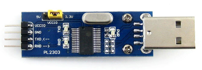
Let's try to connect our MK to the computer via UART. To do this, I use a simple USB - UART TTL (3.3V) (do not forget that our MK has levels - 3.3 V), a converter based on the PL2303 chip.
The STM32 has 3 UART interfaces. Before you use it, you must configure our serial transceiver in the MK. To do this, use the command:
This command starts our UART at baud_rate speed (for example, 9600 or 19200 kbs) with standard parameters (8 data bits, without hardware parity.)
If you need to run the UART in some non-standard mode, then use:
')
here:
To transfer data bytes to our UART, use:
or for an array of data (no matter the text or set of values) we transfer the function:
using a pointer to an array.
Let's write a simple program:
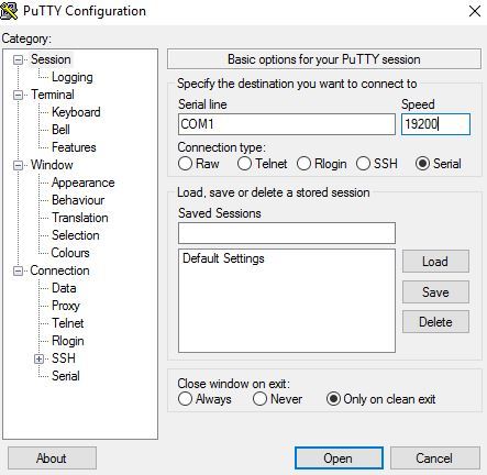
Connect the RX STM32 to the TX Converter and the TX STM32 to the RX Converter and insert it into the USB port of our computer. Open the terminal program (I use PuTTY ), select the SERIAL mode, port speed, for example, 19200 kbs and the COM port that appeared when we connected our USB-TTL converter (you can see in the device manager in the "COM and LPT ports" branch) and click " OPEN. We see our text in the terminal window.
Sending successively several bytes of data, it is necessary to control whether the transmission of the previous one has ended. Each UART has its own status register.
USART1_SR The USART1_SRbits.TC bit is responsible for the completion of the transfer. The UARTx_Write_Text function (char * UART_text) itself controls, before sending the next one, the completion of the transfer of the previous byte.
To read data from the UART microcontroller, use the function:
To know that there is a received byte in the buffer of our UART, we use the function:
In order not to constantly occupy the MC by polling the state of the UART register, you can (and should) use an interrupt. When receiving the next byte, a hardware interrupt from the UART will be called in which we can process the data received by the pop serial interface. To enable the “RX UART” event interrupt, we need to write a logical 1 to the RXNEIE bit in the CR1 register of the used UART module.
as in the case of the timer, when an interrupt occurs, a subroutine is called:
With the help of UART you can connect our MK not only with a computer, but also with many peripheral devices. For example, consider the widely available GSM module SIM800L. I got this module already soldered on a small board. Such cheap can be ordered in China. All the signals necessary for working with the module are placed on the pins of this board, besides the board has a holder for a SIM card.
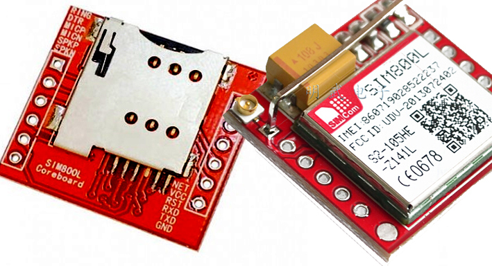
The only thing that is not convenient is the need for supplying this board with voltage from 3.7 to 4.2 V. So you have to either connect an external lithium battery, or convert it to a 4.1 V. Output voltage. Considering the wide distribution of regulated DC-DC, this I think it will not be a particular problem.
We connect our module to the MK, not forgetting that the RX module goes to the TX MK and vice versa. For the Maple mini module we connect the RX to 26 pin (PA9 / UART1TX), TX to 25 (PA10 / UART1RX).
To communicate with the module are used, so called, AT commands. This is a set of terminal commands that the modem understands and performs certain actions in response to them. With the commands of our module can be found in the datasheet , in addition, there is a good article where the work with this module is well written.
We will use 2 UART microcontrollers, UART1 for communication MK-GSM and UART3 for communication MK - computer terminal.
We initialize our UARTs
Our program will require a relatively large number of functions, so we place them in a separate c-file. To do this, press Ctrl + N in Microc, create another file in the project, for example, GSM_SIM800L.. In order for our compiler to understand that some of the functions need to be searched in another file, we add a line at the beginning of the main c-file (you can also connect libraries in the same way.).
To begin with, in the GSM_SIM800L.c file, we write the function that sends the AT command to the module and receives the response from it.
In MicroC, a string is an array of char characters that ends with the value 00 (NULL) meaning the end of the string. The string as a function argument is specified by a pointer to the type char (for example char * nasha_stroka ). MicroC supports the functions of the standard C_String.h library. For example, the above function is used.
this function searches for a substring specified by the pointer * s2 in the string * s1 . The function will return a pointer to the found substring * s2 . (actually returns the string from the beginning * s2 to the end ( NULL character) of the string * s1 ). If the substring * s2 is not found, the function will return NULL . By default in C, passing an array by its name is a pointer to the beginning of the array. If you need to transfer an array c of a particular element, then use ( & array_name [ind] ).
To begin with, it is impassable to give the module a simple command “AT \ r” - the Module should respond to “OK \ r \ n” and agree on the speed of its UART. Any AT command ends with the newline character "\ r" . A module's response to any command can consist of several lines and always ends with “OK \ r \ n” or “ERROR \ r \ n” . A module message, such as an incoming call or SMS message, always ends with "\ r \ n" , and life has simplified that only the last line is usually informative. Reception of such lines, I call the asynchronous answer (not entirely correct, but let it be so).
Perform a few commands needed to configure the module. For simplicity, we will not monitor the module’s responses, although it is easy to check the status for equality 1 when executing each command;
Let us write another function that returns the module’s response (and not just the request status, and maximizes the form we need. In the datasheet for the module, the responses to the AT commands are described using regular expressions about the response feature. known characters).
For example, "AT + GMM \ r \ n" returns the name of the module in the form "\ r \ n SIM_800L \ r \ n \ r \ nOK \ r \ n" . "Bite off" the initial "\ r \ n" and end "\ r \ n \ r \ nOK \ r \ n"
Among the AT commands of the module there is the command “AT + CREG? \ R” . This command will return the status of the module about network registration. If everything is OK and the module is registered the answer should be: "\ r \ n + CREG: 0.1 \ r \ n \ r \ n \ OK \ r \ n" . 0.0 - module is not registered and there is no network search (for example, no SIM card is inserted), 0.2 - module is not registered, network is being searched. Let's write the function of checking the network status of the module, besides, we will return the signal level of the GSM network (for this there is an AT command “AT + CSQ \ r” ).
Now our module is working. If we call him, he will issue a type string to his UART.
"\ r \ n RING \ r \ n + CLIP:" + 380XXXXXXXX ", 145," ",," ", 0 \ r \ n" . With the incoming SMS, the answer will be "\ r \ n + CMTI:" SM ", 10 \ r \ n" , where 10 means that our SMS is stored in memory at number 10. These are the asynchronous answers I called. we will accept and process them in our interrupt handler. I wrote the recognition of the answers I needed most. in principle, how this is done should be clear from the code below.
By controlling the value of the call call variable in the program cycle, you can learn about the incoming call. We can pick up the phone with the help of the command "ATA \ r" , and reset the call - "ATH0 \ r" .
Similarly, controlling the value of the sms variable, we learn about the incoming SMS message. we can read it with the command “AT + CMGR = 2 \ r” where N = SMS number. In response, the module will return a string of the type "\ r \ n + CMGR:" REC READ "," + 380XXXXXXXX "," "," 17/02 / 1,11: 57: 46 + 2 "\ r \ n hellow habrahabr \ r \ n \ r \ nOK \ r \ n ". To parse this line, create a function:
For example:
To send an SMS, use the AT command "AT + CMGS =" + 380XXXXXXXX \ r " . This command responds with the character" \ r \ n> "- an invitation to enter. You can catch this invitation in the module response, I just give a delay in 100 ms. And send SMS text to UART which should end with a symbol with ASCII code 26
The article describes only a small part of the capabilities of both the GSM module and the UART interface of the MK STM32. Nevertheless, I hope that the above information will be useful for understanding the work with the serial interface implemented in the microcontroller.
In the next article I will explain what an I2C bus is, how to work with it, and how to connect an LCD indicator based on the HD44780 controller to the STM32 on a parallel bus and through an I2C I / O extender.
Let's try to connect our MK to the computer via UART. To do this, I use a simple USB - UART TTL (3.3V) (do not forget that our MK has levels - 3.3 V), a converter based on the PL2303 chip.
The STM32 has 3 UART interfaces. Before you use it, you must configure our serial transceiver in the MK. To do this, use the command:
UART_Init(baud_rate); This command starts our UART at baud_rate speed (for example, 9600 or 19200 kbs) with standard parameters (8 data bits, without hardware parity.)
If you need to run the UART in some non-standard mode, then use:
')
UARTx_Init_Advanced(baud_rate, data_bits, parity, stop_bits); here:
- baud_rate — port speed;
- data_bits - the number of data bits, it is possible to use the structures _UART_5_BIT_DATA, _UART_6_BIT_DATA, _UART_7_BIT_DATA, _UART_8_BIT_DATA;
- parity - parity check ( _UART_NOPARITY, _UART_EVENPARITY, _UART_ODDPARITY ), respectively, without parity, parity, odd parity;
- stop_bits - the number of stop bits ( _UART_ONE_STOPBIT, _UART_TWO_STOPBITS ) - 1 or 2 stop bits, respectively;
To transfer data bytes to our UART, use:
UARTx_Write(unsigned int _data); UARTx_Write(char _data); or for an array of data (no matter the text or set of values) we transfer the function:
UARTx_Write_Text(char * UART_text); using a pointer to an array.
Let's write a simple program:
char ourtext[] = "Hellow world"; char *txt_pnt; void main() { UART1_INIT (19200); delay_ms (5); // 5 txt_pnt = &ourtext; UART1_Write_Text(txt_pnt); while (1) { } { Connect the RX STM32 to the TX Converter and the TX STM32 to the RX Converter and insert it into the USB port of our computer. Open the terminal program (I use PuTTY ), select the SERIAL mode, port speed, for example, 19200 kbs and the COM port that appeared when we connected our USB-TTL converter (you can see in the device manager in the "COM and LPT ports" branch) and click " OPEN. We see our text in the terminal window.
Sending successively several bytes of data, it is necessary to control whether the transmission of the previous one has ended. Each UART has its own status register.
USART1_SR The USART1_SRbits.TC bit is responsible for the completion of the transfer. The UARTx_Write_Text function (char * UART_text) itself controls, before sending the next one, the completion of the transfer of the previous byte.
To read data from the UART microcontroller, use the function:
char UARTx_READ() To know that there is a received byte in the buffer of our UART, we use the function:
UART_Data_Ready() returning 1 if the received byte is in the buffer and 0 if it is not there. In this case, we need to constantly monitor whether the UART has received something from our controller. Let's try when receiving, for example, the letter "A" (ASCII code 65) to light the LED on the board: void main() { GPIO_Digital_Output(&GPIOb_BASE, _GPIO_PINMASK_1); UART1_INIT (19200); delay_ms (5); UART1_Write_Text("WAIT CHAR A"); while(1) { if (UART1_Data_Ready()) // UART { if (UART1_READ()== 65) // 65 { GPIOb_ODR.b1 = 1; // } } } } In order not to constantly occupy the MC by polling the state of the UART register, you can (and should) use an interrupt. When receiving the next byte, a hardware interrupt from the UART will be called in which we can process the data received by the pop serial interface. To enable the “RX UART” event interrupt, we need to write a logical 1 to the RXNEIE bit in the CR1 register of the used UART module.
UART1_init (19200); NVIC_IntEnable(IVT_INT_USART1); // IVT_INT_USART1 EnableInterrupts(); // USART1_CR1bits.RXNEIE = 1; // delay_ms (5); as in the case of the timer, when an interrupt occurs, a subroutine is called:
void our_int() iv IVT_INT_USART1 { if (UART1_READ()== 65) GPIOb_ODR.b1 = 1; // A = if (UART1_READ()== 66) GPIOb_ODR.b1 = 0; // B = } With the help of UART you can connect our MK not only with a computer, but also with many peripheral devices. For example, consider the widely available GSM module SIM800L. I got this module already soldered on a small board. Such cheap can be ordered in China. All the signals necessary for working with the module are placed on the pins of this board, besides the board has a holder for a SIM card.
The only thing that is not convenient is the need for supplying this board with voltage from 3.7 to 4.2 V. So you have to either connect an external lithium battery, or convert it to a 4.1 V. Output voltage. Considering the wide distribution of regulated DC-DC, this I think it will not be a particular problem.
We connect our module to the MK, not forgetting that the RX module goes to the TX MK and vice versa. For the Maple mini module we connect the RX to 26 pin (PA9 / UART1TX), TX to 25 (PA10 / UART1RX).
To communicate with the module are used, so called, AT commands. This is a set of terminal commands that the modem understands and performs certain actions in response to them. With the commands of our module can be found in the datasheet , in addition, there is a good article where the work with this module is well written.
We will use 2 UART microcontrollers, UART1 for communication MK-GSM and UART3 for communication MK - computer terminal.
We initialize our UARTs
void main() { UART1_init (19200); // UART UART3_init (19200); // UART GSM NVIC_IntEnable(IVT_INT_USART1); // GSM USART1_CR1bits.RXNEIE = 1; EnableInterrupts(); delay_ms(200); while (1) { } } Our program will require a relatively large number of functions, so we place them in a separate c-file. To do this, press Ctrl + N in Microc, create another file in the project, for example, GSM_SIM800L.. In order for our compiler to understand that some of the functions need to be searched in another file, we add a line at the beginning of the main c-file (you can also connect libraries in the same way.).
#include "GSM_SIM800L." To begin with, in the GSM_SIM800L.c file, we write the function that sends the AT command to the module and receives the response from it.
static char GSM_TEMP[256]; // GSM unsigned short com_status; // 0 - , 1 - , 2 - ( ) unsigned short com_mode = 0; 0 - , 1 - void Clear_GSM_Bufer () // GSM { unsigned int cnt; for (cnt=0; cnt<256; cnt++) GSM_TEMP[cnt] = 0; cntas = 0; } short int gsm_send_at (char *at_cmd) // AT , MicroC { unsigned int brk; // Clear_GSM_Bufer (); // com_status = 2; // " " com_mode = 0; // UART1_Write_Text (at_cmd); // AT - while (com_status == 2 && brk < 50000) // com_status 1 0 { brk++; delay_us(2); } com_mode = 1; // , return com_status; // } void gsm_read() iv IVT_INT_USART1 { GSM_TEMP[cntas] = UART1_READ(); // UART GSM_TEMP if (cntas> 255) cntas = 0; else cntas++; // if (com_mode == 0) // { if (strstr(GSM_TEMP, "OK\r\n") != 0) com_status = 1; // - com_status = 1 if (strstr(GSM_TEMP, "ERROR\r\n") != 0) com_status = 0; //Error - com_status = 0 } } In MicroC, a string is an array of char characters that ends with the value 00 (NULL) meaning the end of the string. The string as a function argument is specified by a pointer to the type char (for example char * nasha_stroka ). MicroC supports the functions of the standard C_String.h library. For example, the above function is used.
char *strstr(char *s1, char *s2); this function searches for a substring specified by the pointer * s2 in the string * s1 . The function will return a pointer to the found substring * s2 . (actually returns the string from the beginning * s2 to the end ( NULL character) of the string * s1 ). If the substring * s2 is not found, the function will return NULL . By default in C, passing an array by its name is a pointer to the beginning of the array. If you need to transfer an array c of a particular element, then use ( & array_name [ind] ).
To begin with, it is impassable to give the module a simple command “AT \ r” - the Module should respond to “OK \ r \ n” and agree on the speed of its UART. Any AT command ends with the newline character "\ r" . A module's response to any command can consist of several lines and always ends with “OK \ r \ n” or “ERROR \ r \ n” . A module message, such as an incoming call or SMS message, always ends with "\ r \ n" , and life has simplified that only the last line is usually informative. Reception of such lines, I call the asynchronous answer (not entirely correct, but let it be so).
Perform a few commands needed to configure the module. For simplicity, we will not monitor the module’s responses, although it is easy to check the status for equality 1 when executing each command;
- "ATE0 \ r" - Turn off the echo (repeat at the output of our team's UARTa)
- "AT + GMM \ r" - Return the name of the module
- "AT + CMGD = 1,4 \ r" - Delete all SMS stored in our module
- “AT + CMGF = 1 \ r” - Turn on ASCII mode for SMS, otherwise it will be harder for us to read them in Unicode characters
- “AT + DDET = 1” - Enable recognition by the DTMF command module
gsm_send_at ("AT\r"); gsm_send_at ("ATE0\r"); gsm_send_at ("AT+CMGD=1,4\r"); gsm_send_at ("AT+CMGF=1\r"); gsm_send_at ("AT+DDET=1\r"); Let us write another function that returns the module’s response (and not just the request status, and maximizes the form we need. In the datasheet for the module, the responses to the AT commands are described using regular expressions about the response feature. known characters).
char *gsm_at_parse (char *at_cmd, char *beg_str, char *end_str) // *at_cmd = // *beg_str = // *beg_str = { char *tempchar; if (gsm_send_at (at_cmd) == 1) // { tempchar = strstr (GSM_TEMP, beg_str); // beg_str tempchar = tempchar + strlen(beg_str); *(strstr (tempchar, end_str)) = 0; // NULL end_str return tempchar; } } For example, "AT + GMM \ r \ n" returns the name of the module in the form "\ r \ n SIM_800L \ r \ n \ r \ nOK \ r \ n" . "Bite off" the initial "\ r \ n" and end "\ r \ n \ r \ nOK \ r \ n"
UART3_Write_Text (gsm_at_parse("AT+GMM\r", "\r\n", "\r\n\r\nOK\r\n")); \\ UART3 ( , ) UART3_Write_Text ("\r\n"); UART3_Write_Text (gsm_at_parse("AT+CCLK?\r", ",", "+")); \\ UART3_Write_Text ("\r\n"); UART3_Write_Text (gsm_at_parse("AT+CSPN?\r", ": \"", "\""); \\ GSM. UART3_Write_Text ("\r\n"); Among the AT commands of the module there is the command “AT + CREG? \ R” . This command will return the status of the module about network registration. If everything is OK and the module is registered the answer should be: "\ r \ n + CREG: 0.1 \ r \ n \ r \ n \ OK \ r \ n" . 0.0 - module is not registered and there is no network search (for example, no SIM card is inserted), 0.2 - module is not registered, network is being searched. Let's write the function of checking the network status of the module, besides, we will return the signal level of the GSM network (for this there is an AT command “AT + CSQ \ r” ).
short int gsm_net_status () { char *tempchar[7]; // int sgr; // dBi if ( gsm_send_at("AT+CREG?\r") == 1) // { if (strstr(GSM_TEMP, "0,1")) // - "+CREG: 0,1" { tempchar = GSM_AT_PARSE ("AT+CSQ\r",": ","," ); // , +CSQ: 17,0, : , sgr = atoi(tempchar); // sgr = -115 + (sgr * 2); // dBi return sgr; // } } return 0; // 0 - . } Now our module is working. If we call him, he will issue a type string to his UART.
"\ r \ n RING \ r \ n + CLIP:" + 380XXXXXXXX ", 145," ",," ", 0 \ r \ n" . With the incoming SMS, the answer will be "\ r \ n + CMTI:" SM ", 10 \ r \ n" , where 10 means that our SMS is stored in memory at number 10. These are the asynchronous answers I called. we will accept and process them in our interrupt handler. I wrote the recognition of the answers I needed most. in principle, how this is done should be clear from the code below.
char *eol // , "\r\n" char callingnumber[14]; // , 13 NULL char last_sms[4]; // char dtmf_in[2]; // DTMF unsigned short callnow; // unsigned short active_call; // unsigned short sms; // void gsm_read() iv IVT_INT_USART1 { GSM_TEMP[cntas] = UART1_READ(); if (cntas> 255) cntas = 0; else cntas++; if (com_mode == 0) { if (strstr(GSM_TEMP, "OK\r\n") != 0) com_status = 1; if (strstr(GSM_TEMP, "ERROR\r\n") != 0) com_status = 0; } // if (com_mode == 1) { if (cntas> 2) eol = strstr(&GSM_TEMP[2], "\r\n"); else eol = 0; // if (eol != 0) // { if (strstr(&GSM_TEMP, "+CLIP") != 0) // "+CLIP" { callnow=1; // temp = strstr(GSM_TEMP, "\"+"); // + - strncpy (callingnumber, temp+1, 13); // callingnumber[] , 13 } if (strstr(&GSM_TEMP, "CARRIER") != 0) // "NO CARRIER" { *callingnumber=0; // ( NULL ) callnow=0; // active_call=0; } if (strstr(&GSM_TEMP, "DTMF") != 0) { temp = strstr(GSM_TEMP, " "); //SIM800 DTMF , DTMF . strncpy(dtmf_in,temp+1,1); // dtmf_in[] } if (strstr(GSM_TEMP, "CMTI")!=0) // { temp = strstr(GSM_TEMP, ","); // ",", strncpy (last_sms, temp + 1, eol - (temp + 1)); // last_sms[] sms=1; // } Clear_GSM_Bufer (); // } } } By controlling the value of the call call variable in the program cycle, you can learn about the incoming call. We can pick up the phone with the help of the command "ATA \ r" , and reset the call - "ATH0 \ r" .
har *nashomer[14] = "+380931234567" if (callnow == 1) { if (strcmp(&callingnumber, "nashomer")==0) // strcmp (*s1, *s2) - 2 , 0 s1 = s2 { gsm_send_at ("ATA\r"); // AT " " active_call = 1; // . } else { gsm_send_at ("ATH0\r"); // AT " " callnow = 0; // } } Similarly, controlling the value of the sms variable, we learn about the incoming SMS message. we can read it with the command “AT + CMGR = 2 \ r” where N = SMS number. In response, the module will return a string of the type "\ r \ n + CMGR:" REC READ "," + 380XXXXXXXX "," "," 17/02 / 1,11: 57: 46 + 2 "\ r \ n hellow habrahabr \ r \ n \ r \ nOK \ r \ n ". To parse this line, create a function:
char *gsm_read_sms (char *sms_num, unsigned short int sms_field) // ( ) ( ), //1 - , //2 - , //3 - { char sms_at[30]; short int res_at; strcat (sms_at, "AT+CMGR="); strcat (sms_at, sms_num); strcat (sms_at, "\r"); res_at = gsm_send_at (sms_at); if (res_at == 1 && sms_field == 1) { *(strstr (GSM_TEMP, "\",\"\",\"")) = 0; sms = 0; return strstr(GSM_TEMP, "\"+") + 1; } if (res_at == 1 && sms_field == 2) { *(strstr(strstr(GSM_TEMP, "\",\"\",\"") + 6, "+")) = 0; sms = 0; return strstr(GSM_TEMP, "\",\"\",\"") + 6; } if (res_at == 1 && sms_field == 3) { *(strstr (GSM_TEMP, "\r\n\r\nOK\r\n")) = 0; sms = 0; return strstr(GSM_TEMP, "\"\r\n") + 3; } return 0; // 0 } For example:
UART3_Write_Text (gsm_read_sms("5",1)); // 5 UART3_Write_Text (gsm_read_sms("2",3)); // 2 To send an SMS, use the AT command "AT + CMGS =" + 380XXXXXXXX \ r " . This command responds with the character" \ r \ n> "- an invitation to enter. You can catch this invitation in the module response, I just give a delay in 100 ms. And send SMS text to UART which should end with a symbol with ASCII code 26
UART1_Write_Text ("AT+CMGS=\""); UART1_Write_Text (nomer); // UART1_Write_Text ("\"\r"); Delay_ms (100); UART1_Write_Text (text); // UART1_Write (26); The article describes only a small part of the capabilities of both the GSM module and the UART interface of the MK STM32. Nevertheless, I hope that the above information will be useful for understanding the work with the serial interface implemented in the microcontroller.
In the next article I will explain what an I2C bus is, how to work with it, and how to connect an LCD indicator based on the HD44780 controller to the STM32 on a parallel bus and through an I2C I / O extender.
Source: https://habr.com/ru/post/321056/
All Articles