Using SVG to draw outline diagrams
Introduction
This article is about how to sketch a simple little shemku of a dozen elements, when you don’t have either Altium or Orcad or even Visio , and Draw.io suddenly broke.
This is not at all difficult: modern browsers support the SVG markup language, with which you can easily and quickly draw a small type scheme in a regular text editor:
Next, I will describe the process of drawing and a few subtleties that are useful. Once again, I’ll emphasize that it’s much easier to draw a large scheme in specialized applications, with automatic tracing, mouse, and other WYSIWYG ’s.
When reading an article, I advise you to submit a
')
Create an outline
A sketch usually contains elements / blocks and links between them, and can be created as a separate text file with the extension .svg or directly embedded in the code of the web page.
When drawing schemes it is convenient to use a specific procedure:
- Create (or copy) used items, for examplehorizontal schottky diode
<defs> ... <g width="30" height="10" id="schottky"> <path style="fill:none;stroke:black;stroke-width:1" d="M0.5,5.5 h10 v-5 l10,5 l-10,5 v-5 m7,-4 v-2 h3 v12 h3 v-2 m-3,-4 h10" /> </g> ... </defs>
orvertical resistor<defs> ... <g width="30" height="10" id="resistor"> <path transform="translate(1,0) rotate(90,15,5)" style="fill:none;stroke:black;stroke-width:1" d="M0.5,5.5 h3 l2,-3 l4,6 l4,-6 l4,6 l4,-6 l4,6 l2,-3 h3" /> </g> ... </defs>
If elements are copied from different places, already at this step it is worth unifying their sizes. Instead of directly editing the coordinates for this, it is easier to use transformations (translate,rotate,scale, etc.).
Please note that element definitions are inside thedefstag, and therefore are not yet displayed. Each element definition must have a uniqueid, which will be required in the next step. - Arrange elements on the scheme and sign them. To do this, use a group from the
usetag to draw an element and one or moretexttags for signatures.Example... <g transform="translate(115,45)"><use xlink:href="#resistor"/><text x="20" font-size="10">R1</text><text x="20" y="10" font-size="8">470k</text></g> ...
When using one line per element, a fairly clear table is obtained. The coordinates of the signatures in the group are relative, so to move the signed element, it is enough to change the coordinates of the group. - Draw connections. For this, it is convenient to use the
pathtag, which makes it easy to draw horizontal and vertical lines.
The following commands are mainly used:M10,5- start drawing from point 10.5h10- horizontal line, 10 pixels to the rightm30,0- jump 30 pixels to the rightv15- vertical line, 15 pixels downm0,30- jump 30 pixels downl-5,-10- oblique line, 5 pixels left and 10 pixels up
- Dot the
iline connections. It does not differ from the arrangement of elements, but it is better to do this after all the connections have already been drawn. - Add beautiful to taste.
Code and picture of a simple scheme
<svg width="100" height="100" xmlns="http://www.w3.org/2000/svg" xmlns:xlink="http://www.w3.org/1999/xlink"> <!-- --> <defs> <circle x="0.5" y="0.5" r="1.5" style="fill:blue;stroke:blue;" id="junction"/> <g width="30" height="10" id="connector"> <path style="fill:none;stroke:black;stroke-width:1" d="M10.5,5.5 a3,3,0,0,1,-6,0 a3,3,0,0,1,6,0 h20" /> </g> <g width="30" height="10" id="resistor"> <path transform="translate(1,0) rotate(90,15,5)" style="fill:none;stroke:black;stroke-width:1" d="M0.5,5.5 h3 l2,-3 l4,6 l4,-6 l4,6 l4,-6 l4,6 l2,-3 h3" /> </g> </defs> <!-- --> <g transform="translate(5, 10)"><use xlink:href="#connector"/><text x="20" font-size="10">+</text> </g> <g transform="translate(25,40)"><use xlink:href="#resistor"/> <text x="-5" y="10" font-size="10">R1</text></g> <g transform="translate(5, 70)"><use xlink:href="#connector"/><text x="20" font-size="10">-</text> </g> <!-- --> <path d="M35.5,15.5 h5 v15 m0,30 v15 h-5" stroke="red" fill="none"/> <path d="M40.5,15.5 h25 v60 h-25" stroke="red" fill="none"/> <!-- --> <use xlink:href="#junction" transform="translate(40,15)"/> <use xlink:href="#junction" transform="translate(40,75)"/> <!-- --> <text x="50" y="88" width="100" text-anchor="middle" font-family="cursive" font-size="10"></text> <text x="50" y="98" width="100" text-anchor="middle" font-family="monospace" font-size="10"></text> </svg> Schema code from the beginning of the article
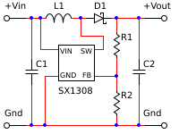
<svg width="200" height="150" xmlns="http://www.w3.org/2000/svg" xmlns:xlink="http://www.w3.org/1999/xlink"> <desc>Step-up DC-DC converter</desc> <defs> <circle x="0.5" y="0.5" r="1.5" style="fill:blue;stroke:blue;" id="junction"/> <g width="30" height="10" id="connector"> <path style="fill:none;stroke:black;stroke-width:1" d="M10.5,5.5 a3,3,0,0,1,-6,0 a3,3,0,0,1,6,0 h20" /> </g> <g width="30" height="10" id="connector180"> <path transform="translate(1,1) rotate(180,15,5)" style="fill:none;stroke:black;stroke-width:1" d="M10.5,5.5 a3,3,0,0,1,-6,0 a3,3,0,0,1,6,0 h20" /> </g> <g width="30" height="10" id="resistor"> <path transform="translate(1,0) rotate(90,15,5)" style="fill:none;stroke:black;stroke-width:1" d="M0.5,5.5 h3 l2,-3 l4,6 l4,-6 l4,6 l4,-6 l4,6 l2,-3 h3" /> </g> <g width="30" height="10" id="capacitor"> <path transform="translate(1,0) rotate(90,15,5)" style="fill:none;stroke:black;stroke-width:1" d="M0.5,5.5 h13 m0,-7 v14 m4,0 v-14 m0,7 h13" /> </g> <g width="30" height="10" id="inductance"> <path style="fill:none;stroke:black;stroke-width:1" d="M0.5,5.5 h0.7 a5,10,0,0,1,9.3,5 a5,10,0,0,1,10,0 a5,10,0,0,1,9.3,-5 h0.7" /> </g> <g width="30" height="10" id="schottky"> <path style="fill:none;stroke:black;stroke-width:1" d="M0.5,5.5 h10 v-5 l10,5 l-10,5 v-5 m7,-4 v-2 h3 v12 h3 v-2 m-3,-4 h10" /> </g> <g width="40" height="40" id="stepup"> <rect x="0.5" y="0.5" width="40" height="40" style="fill:none;stroke:black;stroke-width:1px;"/> <text x="2" y="10" font-size="8">VIN</text> <text x="2" y="37" font-size="8">GND</text> <text x="25" y="10" font-size="8">SW</text> <text x="27" y="37" font-size="8">FB</text> </g> </defs> <g transform="translate(0,15)"><use xlink:href="#connector"/><text x="5" y="-5" font-size="10">+Vin</text></g> <g transform="translate(0,135)"><use xlink:href="#connector"/><text x="5" y="-5" font-size="10">Gnd</text></g> <g transform="translate(160,15)"><use xlink:href="#connector180"/><text y="-5" font-size="10">+Vout</text></g> <g transform="translate(160,135)"><use xlink:href="#connector180"/><text y="-5" font-size="10">Gnd</text></g> <g transform="translate(65,50)"><use xlink:href="#stepup"/><text y="55" font-size="10">SX1308</text></g> <g transform="translate(115,45)"><use xlink:href="#resistor"/><text x="20" font-size="10">R1</text></g> <g transform="translate(115,110)"><use xlink:href="#resistor"/><text x="20" font-size="10">R2</text></g> <g transform="translate(20,75)"><use xlink:href="#capacitor"/><text x="20" font-size="10">C1</text></g> <g transform="translate(140,75)"><use xlink:href="#capacitor"/><text x="20" font-size="10">C2</text></g> <g transform="translate(50,15)"><use xlink:href="#inductance"/><text x="10" y="-5" font-size="10">L1</text></g> <g transform="translate(95,15)"><use xlink:href="#schottky"/><text x="10" y="-5" font-size="10">D1</text></g> <path d="M30.5,20.5 h20 m30,0 h15 m30,0 h35" stroke="red" fill="none"/> <path d="M35.5,20.5 v45 m0,30 v45" stroke="red" fill="none"/> <path d="M130.5,20.5 v15 m0,30 v35 m0,30 v10" stroke="red" fill="none"/> <path d="M155.5,20.5 v45 m0,30 v45" stroke="red" fill="none"/> <path d="M45.5,20.5 v35 h20" stroke="red" fill="none"/> <path d="M50.5,140.5 v-55 h15" stroke="red" fill="none"/> <path d="M90.5,20.5 v20 h25 v15 h-10" stroke="red" fill="none"/> <path d="M105.5,85.5 h25" stroke="red" fill="none"/> <path d="M30.5,140.5 h130" stroke="red" fill="none"/> <use xlink:href="#junction" transform="translate(35,20)"/> <use xlink:href="#junction" transform="translate(45,20)"/> <use xlink:href="#junction" transform="translate(90,20)"/> <use xlink:href="#junction" transform="translate(130,20)"/> <use xlink:href="#junction" transform="translate(155,20)"/> <use xlink:href="#junction" transform="translate(130,85)"/> <use xlink:href="#junction" transform="translate(35,140)"/> <use xlink:href="#junction" transform="translate(50,140)"/> <use xlink:href="#junction" transform="translate(130,140)"/> <use xlink:href="#junction" transform="translate(155,140)"/> </svg> Subtle drawing
In general, drawing with SVG is quite simple. Below are some not very obvious, but able to save some time details.
Why lines are blurred
SVG uses sub-pixel precision when drawing lines. Therefore, for lines with an odd number of pixels thick, the coordinates of the beginning and end must be located in the middle of the pixel. If only relative coordinates were used for drawing, then you can simply shift the coordinates of the starting point by 0.5.0.5. The universal solution is
translate(0.5,0.5) .Circles or arcs
A circle can be drawn with the
circle tag or with the a command (from Arc - arc) of the path tag. If there is a choice, use circle .The only justification for drawing a circle with arcs is if you want to draw an element containing circles with a single
path tag. This requires two successive arcs: ... a3,3,0,0,1,-6,0 a3,3,0,0,1,6,0 ... , where 3 is the radius of the circle, and 6 is its diameter.Using items from other files
Very simple - instead of
<use xlink:href="#connector"/> , <use xlink:href="library.svg#connector"/> .Separate file or embedded HTML code
A separate file is much more convenient, but
- if .svg contains links to other .svg, then it should be included in the HTML
objecttag<object data="image.svg" type="image/svg+xml"></object> - if .svg does not contain links to other .svg, then the
imagetag works no worse than theobjecttag<img src="image.svg"/> <object data="image.svg" type="image/svg+xml"></object> - Inline image elements are easier and faster to set up via CSS
Where to get images of elements
Draw by yourself or search
in Google
At the same time, it sometimes turns out to be faster to draw by yourself than to choose the one that is suitable from the library. For myself, I started collecting my
library
How to get .pdf, .png, .jpg, etc. from .svg
The easiest thing is to open .svg in Edge and save the image as .png. If the browser does not allow this, then you can print .svg to a PDF printer or use PrintScreen.
There are also a bunch of online services, such as CloudConvert. Unfortunately, not all services correctly handle transparency and / or non-standard fonts.
Source: https://habr.com/ru/post/320504/
All Articles