ESP8266 + PCA9685 + LUA
Hi Habr! By the will of fate, I was lucky enough to lead a circle in robotics in one of the schools, the subject of the work touched upon work with servo drives.

The development platform was chosen esp8266, because it needed wifi, and its price was reasonable!
The firmware was used with LUA, the build was custom (it was going to be here , remember to include I2C and BIT in the list of supported libraries).
')
As we know, the servos are controlled by PWM, the esp8266 is onboard with the PWM problem, but there is at least I2C, and what to think of bicycles and others, the PCA9685 controller with a 12-bit 16-channel interface onboard was found + external power I2C, what else is needed to control servos, NOTHING!
Googling found libraries for working with PCA9685 in python, arduino, under Lua, only one mention was made, and then at the level “it works, you can think of something,” it didn’t work for me!
Who is not interested in the description of PCA9685 and it is in the subject, to that immediately turnip .
Description of the controller for understanding:
The controller, as you already understood, works according to the I2C protocol, the essence of its work in the case of PCA9685 is the transfer of the register number for reading or writing to it
For work, we will be interested only in 3 registers that are responsible for settings (0x00, 0x01 and 0xFE), and several types (grouped by addresses) of registers working in a pair that are responsible for working with PWM, we will not describe the work with additional addresses here !
More about the contents of registers, bytes and bits, how to work with it and what it is
The rule is simple!
1 register - 1 byte of information
Who does not understand what registers are, it is the same 1 byte which contains the address in a certain area of memory, no more, they are all presented in hexadecimal numbering system, i.e. it can be converted to 10-digit for general understanding!
There are also parameters that take two registers, for example, 0x06 and 0x07, which are currently responsible for the switching point of PWM on channel 0!
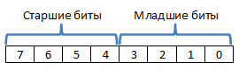
For those who do not know what bits are, how many are in bytes, where we have high and low bits
In 1 byte - 8 bits , numbering from the right to the left , starting from 0, that is, we have 8 bits, from 0 to 7, high bits on the left, low bits on the right. If we have a certain parameter described by 2 bytes, then we must understand which of them is responsible for the high-order bits and which one is responsible for the low-order bits!
Example (when the parameter is described by 1 register):
We have a certain number 45, we need to write it in a certain register, in order to understand what bits will be written, let's translate this all into a 2-hrychny system and into a hexadecimal
45 → 00101101
We received a set of bits in the amount of 8 pieces, respectively, these bytes will be written to the register at a specific address
45 → 0x2D (value)
Example (when the parameter is described by 2 registers):
Take a number that goes beyond the limit of 1 byte, from 256 and up, well, no more than 12 bits, since our controller is 12-bit
3271 → 0000 1100 11000111
As you see, we received 2 times 8 bits, that is, 16 bits, since we are only interested in the first 12 bits, then we can safely discard the last 4 bits, 1100 11000111 comes out, as we remember the upper bits on the left, the lower ones, the numbering right to left, i.e. to divide this value into 2 bytes which will be written separately in each register, we need to divide these bits into 2 parts
1) 1100 → 0x0C (high 4 bits)
2) 11000111 → 0xC7 (lower 8 bits)
The implementation of this separation in Lua is performed using bit operations.
More information about the parameters:
As stated above, we will consider working with 3 registers.
3) 0xFE - responsible for the PWM frequency (PRE_SCALE)
To set the PWM frequency, the clock source is used, the internal clock source operates at a frequency of 25MHz, the value that is transmitted to the register must be calculated using the formula, and then written to the register
Calculate PRE_SCALE
\ begin {eqnarray}
PRE \ _SCALE & = & round (\ frac {F_ {osc}} {4096 * F_ {pwm}}) - 1
\ end {eqnarray}
Fosc = 25,000,000
Fpwm = desired PWM frequency
4096 - number of values contained in 12 bits
Ie to set the frequency to 50Hz
\ begin {eqnarray}
PRE \ _SCALE & = & round (\ frac {25000000} {4096 * 50}) - 1 = 121
\ end {eqnarray}
You must write to the register 0xFE value 121 (0x79)
Fpwm calculation
\ begin {eqnarray}
F_ {pwm} & = & \ frac {F_ {osc}} {4096 * (PRE \ _SCALE + 1)}
\ end {eqnarray}
\ begin {eqnarray}
F_ {pwm} & = & \ frac {25000000} {4096 * (121 + 1)} = 50
\ end {eqnarray}
Functions for working with registers 0x00 and 0x01
1) 0x00 - parameters
7 bits - RESTART
6 bits - EXTCLK
5 bits - AI
4 bits - SLEEP
3 bits - SUB1 *
2 bits - SUB2 *
1 bit - SUB3 *
0 bit - ALLCALL
RESTART - sets the restart flag
EXTCLK - uses, - 1 external , 0 internal clock source
AI - enables (1) and disables (0) register auto-increment when writing data to the register, i.e. you can send immediately 2 bytes in a row with the address of the first register , and 2 bytes will be written to the address of the register + 1
SLEEP - put the controller into power saving mode (1), and vice versa (0)
ALLCALL - allows (1) the module to respond to the addresses of the general call (working with PWM), 0 in the opposite case
* - do not consider
2) 0x01 - parameters
7 bits - not used
6 bits - not used
5 bits - not used
4 bits - INVRT
3 bits - OCH
2 bits - OUTDRV
1, 0 bits - OUTNE
INVRT - inverting output signals, (0) - inverting is disabled, (1) - inverting is enabled
OCH - the method of applying the value for PWM over I2C channel (1 according to ASK, 0 - according to STOP)
OUTDRV - the ability to connect external drivers (1), without external drivers (0)
OUTNE - type of external driver connection (0 - 3)
Work with PWM
The controller has 16 channels, for each channel 4 addresses are allocated, of which 2 are for switching on and 2 for switching off
Example:
0 channel
Inclusion Registers
0x06 (L, low 8 bits)
0x07 (H, high 4 bits)
Shutdown registers
0x08 (L, low 8 bits)
0x09 (H, high 4 bits)
respectively, +4 to each address of the register is the address of the register of a certain type on a certain channel
Functions for working with PWM
Accordingly, a simple example for working with the module
PS I will be glad to any clarifications and comments, I will be especially grateful for a more detailed explanation about OUTDRV and OUTNE, since I could not find a simpler explanation
The development platform was chosen esp8266, because it needed wifi, and its price was reasonable!
The firmware was used with LUA, the build was custom (it was going to be here , remember to include I2C and BIT in the list of supported libraries).
')
As we know, the servos are controlled by PWM, the esp8266 is onboard with the PWM problem, but there is at least I2C, and what to think of bicycles and others, the PCA9685 controller with a 12-bit 16-channel interface onboard was found + external power I2C, what else is needed to control servos, NOTHING!
Googling found libraries for working with PCA9685 in python, arduino, under Lua, only one mention was made, and then at the level “it works, you can think of something,” it didn’t work for me!
Who is not interested in the description of PCA9685 and it is in the subject, to that immediately turnip .
Description of the controller for understanding:
The controller, as you already understood, works according to the I2C protocol, the essence of its work in the case of PCA9685 is the transfer of the register number for reading or writing to it
-- read = function (this, reg) -- I2C i2c.start(this.ID) -- if not i2c.address(this.ID, this.ADDR, i2c.TRANSMITTER) then return nil end -- ( , ) i2c.write(this.ID, reg) -- i2c.stop(this.ID) -- I2C i2c.start(this.ID) -- if not i2c.address(this.ID, this.ADDR, i2c.RECEIVER) then return nil end -- 1 c = i2c.read(this.ID, 1) -- i2c.stop(this.ID) -- return c:byte(1) end, -- write = function (this, reg, ...) i2c.start(this.ID) if not i2c.address(this.ID, this.ADDR, i2c.TRANSMITTER) then return nil end i2c.write(this.ID, reg) len = i2c.write(this.ID, ...) i2c.stop(this.ID) return len end, For work, we will be interested only in 3 registers that are responsible for settings (0x00, 0x01 and 0xFE), and several types (grouped by addresses) of registers working in a pair that are responsible for working with PWM, we will not describe the work with additional addresses here !
More about the contents of registers, bytes and bits, how to work with it and what it is
The rule is simple!
1 register - 1 byte of information
Who does not understand what registers are, it is the same 1 byte which contains the address in a certain area of memory, no more, they are all presented in hexadecimal numbering system, i.e. it can be converted to 10-digit for general understanding!
There are also parameters that take two registers, for example, 0x06 and 0x07, which are currently responsible for the switching point of PWM on channel 0!
For those who do not know what bits are, how many are in bytes, where we have high and low bits
In 1 byte - 8 bits , numbering from the right to the left , starting from 0, that is, we have 8 bits, from 0 to 7, high bits on the left, low bits on the right. If we have a certain parameter described by 2 bytes, then we must understand which of them is responsible for the high-order bits and which one is responsible for the low-order bits!
Example (when the parameter is described by 1 register):
We have a certain number 45, we need to write it in a certain register, in order to understand what bits will be written, let's translate this all into a 2-hrychny system and into a hexadecimal
45 → 00101101
We received a set of bits in the amount of 8 pieces, respectively, these bytes will be written to the register at a specific address
45 → 0x2D (value)
Example (when the parameter is described by 2 registers):
Take a number that goes beyond the limit of 1 byte, from 256 and up, well, no more than 12 bits, since our controller is 12-bit
3271 → 0000 1100 11000111
As you see, we received 2 times 8 bits, that is, 16 bits, since we are only interested in the first 12 bits, then we can safely discard the last 4 bits, 1100 11000111 comes out, as we remember the upper bits on the left, the lower ones, the numbering right to left, i.e. to divide this value into 2 bytes which will be written separately in each register, we need to divide these bits into 2 parts
1) 1100 → 0x0C (high 4 bits)
2) 11000111 → 0xC7 (lower 8 bits)
The implementation of this separation in Lua is performed using bit operations.
-- bit.rshift(3271, 8) -- 00001100 11000111 -> 00001100 -- -- 00001100 -- bit.band(3271, 0xFF) -- 00001100 11000111 -- 11111111 -- -- 00000000 11000111 More information about the parameters:
As stated above, we will consider working with 3 registers.
3) 0xFE - responsible for the PWM frequency (PRE_SCALE)
To set the PWM frequency, the clock source is used, the internal clock source operates at a frequency of 25MHz, the value that is transmitted to the register must be calculated using the formula, and then written to the register
Calculate PRE_SCALE
\ begin {eqnarray}
PRE \ _SCALE & = & round (\ frac {F_ {osc}} {4096 * F_ {pwm}}) - 1
\ end {eqnarray}
Fosc = 25,000,000
Fpwm = desired PWM frequency
4096 - number of values contained in 12 bits
Ie to set the frequency to 50Hz
\ begin {eqnarray}
PRE \ _SCALE & = & round (\ frac {25000000} {4096 * 50}) - 1 = 121
\ end {eqnarray}
You must write to the register 0xFE value 121 (0x79)
Fpwm calculation
\ begin {eqnarray}
F_ {pwm} & = & \ frac {F_ {osc}} {4096 * (PRE \ _SCALE + 1)}
\ end {eqnarray}
\ begin {eqnarray}
F_ {pwm} & = & \ frac {25000000} {4096 * (121 + 1)} = 50
\ end {eqnarray}
getFq = function(this) local fq = this:read(this.PRE_SCALE) return math.floor(25000000 / ( fq + 1) / 4096) end, setFq = function(this, fq) local fq = math.floor(25000000 / ( fq * 4096 ) - 1) local oldm1 = this:read(0x00); this:setMode1(bit.bor(oldm1, this.SLEEP)) this:write(this.PRE_SCALE, fq) this:setMode1(oldm1) return nil end Functions for working with registers 0x00 and 0x01
getMode1 = function(this) return this:read(0x00) end, setMode1 = function(this, data) return this:write(0x00, data) end, getMode2 = function(this) return this:read(0x01) end, setMode2 = function(this, data) return this:write(0x01, data) end, getChan = function(this, chan) return 6 + chan * 4 end, 1) 0x00 - parameters
7 bits - RESTART
6 bits - EXTCLK
5 bits - AI
4 bits - SLEEP
3 bits - SUB1 *
2 bits - SUB2 *
1 bit - SUB3 *
0 bit - ALLCALL
RESTART - sets the restart flag
EXTCLK - uses, - 1 external , 0 internal clock source
AI - enables (1) and disables (0) register auto-increment when writing data to the register, i.e. you can send immediately 2 bytes in a row with the address of the first register , and 2 bytes will be written to the address of the register + 1
SLEEP - put the controller into power saving mode (1), and vice versa (0)
ALLCALL - allows (1) the module to respond to the addresses of the general call (working with PWM), 0 in the opposite case
* - do not consider
-- MODE 1 reset = function(this) local mode1 = this:getMode1() mode1 = bit.set(mode1, 7) this:setMode1(mode1) mode1 = bit.clear(mode1, 7) this:setMode1(mode1) end, getExt = function(this) return bit.isset(this:getMode1(), 6) end, setExt = function(this, ext) local mode1 = this:getMode1() if (ext) then mode1 = bit.clear(mode1, 6) else mode1 = bit.set(mode1, 6) end this:setMode1(mode1) end, getAi = function(this) return bit.isset(this:getMode1(), 5) end, setAi = function(this, ai) local mode1 = this:geMode1() if (ai) then mode1 = bit.clear(mode1, 5) else mode1 = bit.set(mode1, 5) end this:setMode1(mode1) end, getSleep = function(this) return bit.isset(this:getMode1(), 4) end, setSleep = function(this, sleep) local mode1 = this:geMode1() if (sleep) then mode1 = bit.clear(mode1, 4) else mode1 = bit.set(mode1, 4) end this:setMode1(mode1) end, getAC = function(this) return bit.isset(this:getMode1(), 0) end, setAC = function(this, ac) local mode1 = this:geMode1() if (ac) then mode1 = bit.clear(mode1, 0) else mode1 = bit.set(mode1, 0) end this:setMode1(mode1) end, 2) 0x01 - parameters
7 bits - not used
6 bits - not used
5 bits - not used
4 bits - INVRT
3 bits - OCH
2 bits - OUTDRV
1, 0 bits - OUTNE
INVRT - inverting output signals, (0) - inverting is disabled, (1) - inverting is enabled
OCH - the method of applying the value for PWM over I2C channel (1 according to ASK, 0 - according to STOP)
OUTDRV - the ability to connect external drivers (1), without external drivers (0)
OUTNE - type of external driver connection (0 - 3)
-- MODE 2 getInvrt = function(this) return bit.isset(this:getMode2(), 4) end, setInvrt = function(this, invrt) local mode2 = this:geMode2() if (invrt) then mode2 = bit.clear(mode1, 4) else mode2 = bit.set(mode1, 4) end this:setMode2(mode2) end, getInvrt = function(this) return bit.isset(this:getMode2(), 4) end, setInvrt = function(this, invrt) local mode2 = this:geMode2() if (invrt) then mode2 = bit.clear(mode2, 4) else mode2 = bit.set(mode2, 4) end this:setMode2(mode2) end, getOch = function(this) return bit.isset(this:getMode2(), 3) end, setOch = function(this, och) local mode2 = this:geMode2() if (och) then mode2 = bit.clear(mode2, 3) else mode2 = bit.set(mode2, 3) end this:setMode2(mode2) end, getOutDrv = function(this) return bit.isset(this:getMode2(), 2) end, setOutDrv = function(this, outDrv) local mode2 = this:geMode2() if (outDrv) then mode2 = bit.clear(mode2, 2) else mode2 = bit.set(mode2, 2) end this:setMode2(mode2) end, getOutNe = function(this) return bit.band(this:getMode2(), 3) end, setOutNe = function(this, outne) local mode2 = this:geMode2() this:setMode2(bit.bor(mode2, bit.band(outne, 3))) end, getMode2Table = function(this) return { invrt = this:getInvrt(), och = this:getOch(), outDrv = this:getOutDrv(), outNe = this:getOutNe(), } end, Work with PWM
The controller has 16 channels, for each channel 4 addresses are allocated, of which 2 are for switching on and 2 for switching off
Example:
0 channel
Inclusion Registers
0x06 (L, low 8 bits)
0x07 (H, high 4 bits)
Shutdown registers
0x08 (L, low 8 bits)
0x09 (H, high 4 bits)
respectively, +4 to each address of the register is the address of the register of a certain type on a certain channel
Functions for working with PWM
-- CNAHEL setOn = function(this, chan, data) this:write(this:getChan(chan), bit.band(data, 0xFF)) this:write(this:getChan(chan) + 1, bit.rshift(data, 8)) end, setOff = function(this, chan, data) this:write(this:getChan(chan) + 2, bit.band(data, 0xFF)) this:write(this:getChan(chan) + 3, bit.rshift(data, 8)) end, setOnOf = function(this, chan, dataStart, dataEdn) this:setOn(chan, dataStart) this:setOff(chan, dataEdn) end, Accordingly, a simple example for working with the module
-- require('pca9685') -- , i2c pca = pca9685.create(0, 0x40) -- GPIO c SDA SCL pca:init(1, 2) -- pca:setMode1(0x01) pca:setMode2(0x04) -- pca:setFq(50) -- pca:setOnOf(0, 200, 600) PS I will be glad to any clarifications and comments, I will be especially grateful for a more detailed explanation about OUTDRV and OUTNE, since I could not find a simpler explanation
Source: https://habr.com/ru/post/320006/
All Articles