How to avoid self-excitation of cellular amplifier
Self-excitation of the cellular amplifier is the most unpleasant and dangerous mode of its operation. The article describes how to determine that the amplifier is in self-excitation mode, and how to avoid stalling in this mode.
If you incorrectly install a mobile communications amplifier or 3G / 4G internet, there is always the risk of meeting with the staff of the radio frequency service. Most likely, the first time they politely ask to turn off the device and no longer turn on.
A properly installed repeater will never attract extra attention. Ideally, from the point of view of the base station, the nature of its radiation should not differ from the nature of the radiation of an ordinary mobile phone. Therefore, for the engineer-installer of repeaters, there are two basic principles:
')
Both of these principles are successfully implemented at the stage of creating a project for an object. So easily cut off 90% of all possible troubles.
The violation of these principles leads to the appearance of a huge number of potential problems, the most important of which is oscillations, sometimes called simply “self-excitation”. Many people know that if you bring the microphone to the speaker, there will be a sharp whistle. So, self-excitation of the repeater is a similar phenomenon, but it is arranged somewhat more complicated.
In any case, most of the problem situations are caused by feedback arising between the internal and external antennas. The repeater is a bi-directional amplifier, amplifying signals in both directions, i.e. signals from the base station to the subscriber (downlink - Downlink) and from the subscriber to the base station (uplink - Uplink). On repeaters that do not have manual gain control, cases of self-excitation on the Downlink channel are much more common, since the downlink channel gain is always 5-10 dB higher than the Uplink channel.
Globally, there are two unpleasant situations of self-excitation: an increased noise level, which can be unstable and periodically fall into oscillation, and the oscillations themselves. Consider both cases.
If the feedback has a negative gain of between 0 and about –10 dB, this will not put the repeater in oscillation mode, but will increase the overall noise level of the entire system. On the phone, it will look like a confident reception with 4-5 "sticks". But at the same time the connection will be very unstable, since the signal-to-noise ratio is very small.
What to do? First of all, you need to improve the isolation between the antennas (put them in a different place and / or change the orientation of the polarization plane) or reduce the gain of the repeater. The first option is always preferable, as it will improve the signal-to-noise ratio.
Noise with a low level of feedback is an unstable phenomenon that turns into oscillations when the radio frequency environment changes. This can be caused both by an increase in the downlink signal level (for example, another BS suddenly suddenly powerfully operated at a close frequency), or by a change in the ratio of the phases of the downlink signals and the parasitic signal from the internal antenna at the point of the external antenna. In the latter case, sad things can happen. If the downlink signal and the parasitic signal from the internal antenna are in antiphase, then they are partially mutually quenching each other. This situation only worsens the noise level. If they are in phase and the spurious signal from the internal antenna has sufficient power, then the system switches to oscillation mode. Since the signals of mobile communication are waves of the centimeter range, the displacement of one of the antennas by just 10 cm can both improve and worsen the overall situation. Also, the phases of snow may stick to the antenna, changing the layout of rooms, opening windows and doors, etc.
Everything is clear: the gain is greater than 0 dB, the system immediately goes into oscillation mode, the repeater whistles. To treat in standard ways: first of all, we increase the isolation, if necessary, reduce the gain.
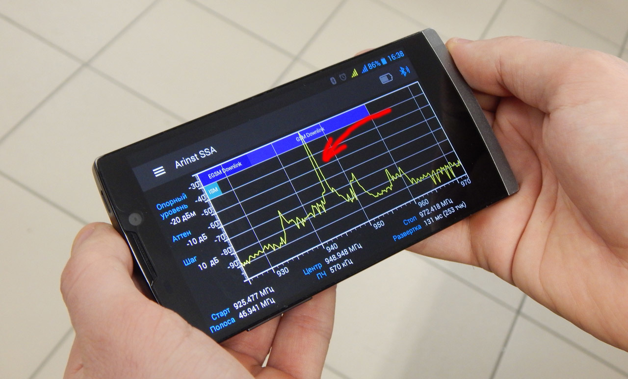
2.2.1. Here’s what the Downlink signal spectrum will look like next to the internal antenna:

On the spectrum analyzer screen, all Downlink signals constantly change except for one signal in the 957 MHz range, which has a more or less stable amplitude and frequency. This is a classic self-excitation in the downlink downlink. To eliminate it, you need to place external and internal antennas. Internal antennas can be rotated to horizontal polarization, this is always useful because it increases the isolation between the antennas by at least 10 dB. Or it is necessary to reduce the gain of the repeater. But when the gain of the repeater decreases, a weaker signal is always received, which is not always acceptable.
It can be seen that the signals have average levels of -75 ...- 90 dBm, so it seems intuitively that reducing the gain is impractical, since the levels will fall even lower. But it is not. Self-excitation causes the repeater to operate in overload mode. If the amplifier has AGC, then it works in the mode of maximum attenuation of the signal level. Therefore, by reducing the gain of the repeater, you can end up with a much larger signal, but without oscillation.
2.2.2. Oscillation in the channel Uplink. This is the most unpleasant oscillation in the sense that the amplifier can give strong interference to telecom operators and other subscribers.
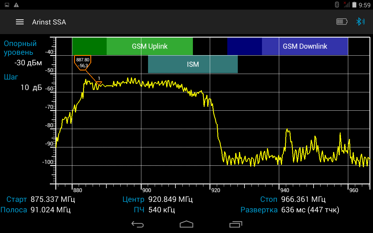
Here is an example of a bad spectral image in the Uplink channel next to an external antenna:

The screenshot shows two sources of spurious radiation:
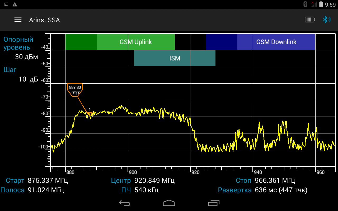
Below is an example of a high-noise spectrum in the Uplink channel, measured on a test antenna near an external repeater antenna. Such noise will degrade the BS. The operator must contact the radio frequency service to eliminate the causes of interference.
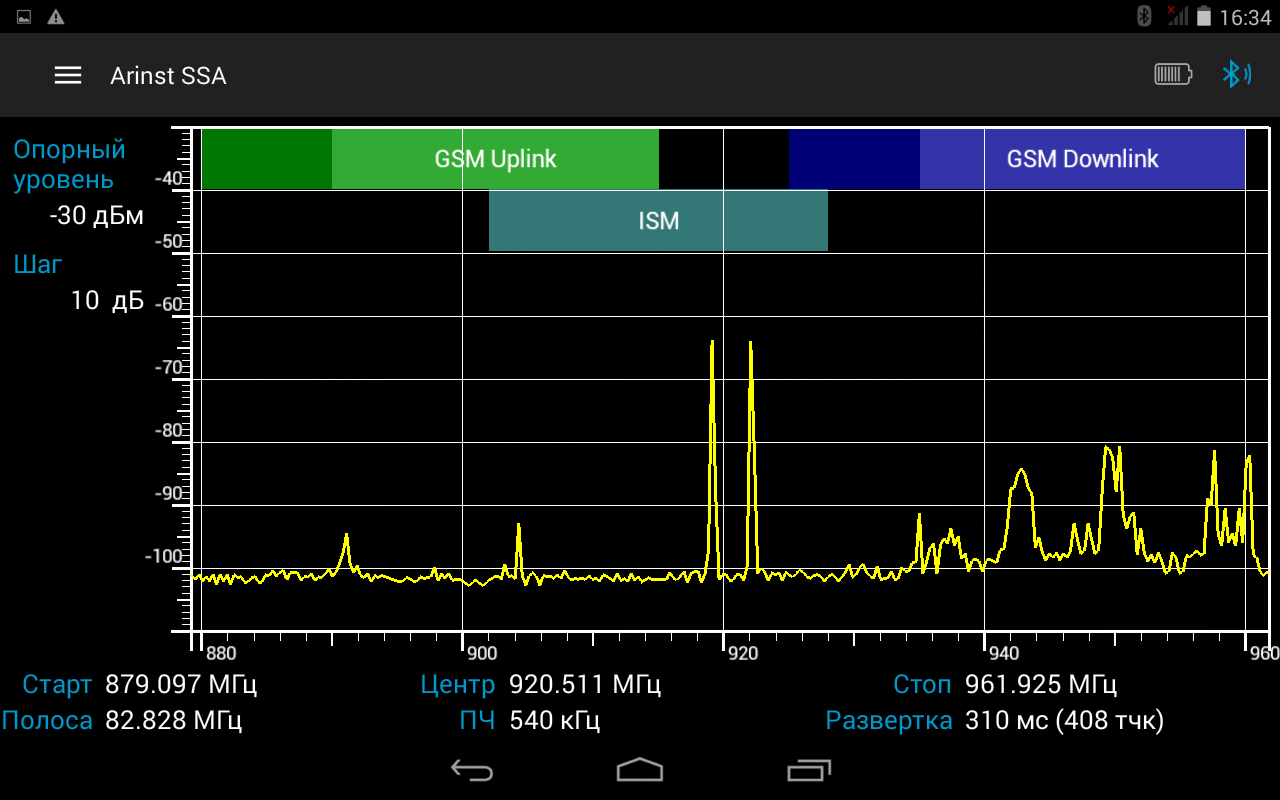
Here is an example of a normal signal, noise around -80 dBm:
Parasitic internal oscillation occurs at a frequency close to the frequencies of the Rx / Tx repeater, or is in the middle between them. It can occur, firstly, because of the poor quality of the repeater itself, and, secondly, because of the deterioration of the operating parameters of duplexers due to the mismatch of the radio-frequency inputs or the use of low-quality antennas. Due to these reasons, the transmission coefficient between the Rx and Tx channels increases in the duplexer, which causes internal self-excitation.
In addition, spurious internal oscillation in addition to contamination of the radio frequency spectrum worsens the noise performance of the repeater and reduces its gain.
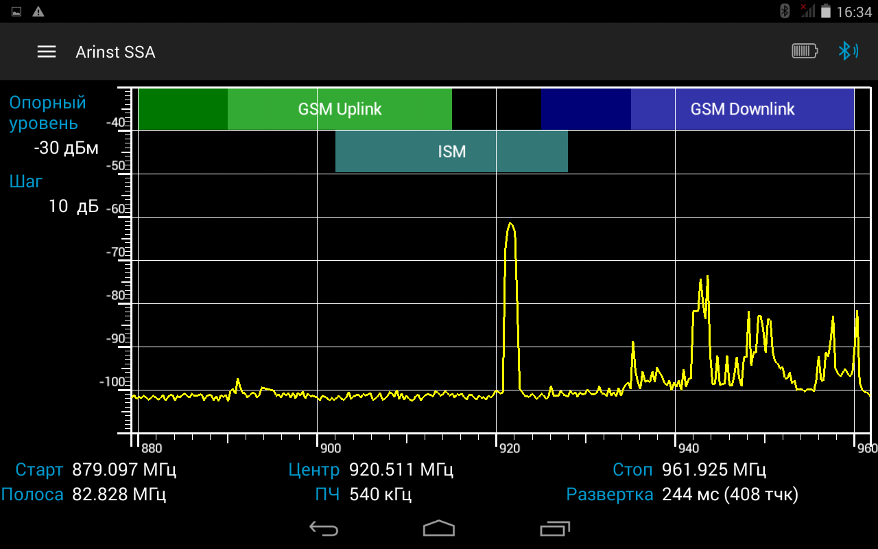
On the spectrum analyzer screen, this may look like one or two spectral bursts at a frequency approximately midway between the Uplink and Downlink ranges:
Or it can be one wide or narrow spectral surge at a frequency approximately midway between the Uplink and Downlink bands:

It can also be a single spectral burst with an unstable amplitude and frequency at a frequency approximately between the Uplink and Downlink bands:
It is difficult to say unequivocally which level of the repeater signal is optimal. Here it is necessary to act on the situation. In the most general case, the noise level in the Uplink channel, measured at a distance of 1-2 meters from an external antenna using a measuring 8-9 dB antenna, should be approximately -80 dBm (with a spectrum analyzer bandwidth connected to the measuring antenna equal to 500 kHz).
If the repeater is mounted in a deaf place at a great distance from the base stations, then you can safely use a repeater with high gain and high output power; however, even the level of the noise signal emitted by an external repeater antenna, equal to -60 ... ..- 50 dBm, would be acceptable. However, if the same repeater with the same noise level works in dense urban development, then it will simply “light” one of the nearest base stations with such a signal (especially if the external antenna of the repeater is directed towards the base station). The operator will stop “seeing” remote subscribers for your noise and will contact the radio frequency center in order to find and eliminate the source of interference.
After commissioning, it is necessary to take a spectrum analyzer with a measuring antenna connected to it and take measurements near all installed internal and external antennas. The shelves of repeater noise radiation should be relatively even and have an acceptable level.
It is necessary to bring a palm to each antenna. In this way, we slightly shift the phase and level of the reverse signal. If the oscillations did not appear, then everything is fine.
You can also temporarily connect a repeater with a higher gain. The system should have a gain margin, so a repeater with a higher gain should not cause oscillations. If everything is good, then we change the amplifier to the old one.
Authors - Dakhin Maxim, Siradze Ilya.
If you incorrectly install a mobile communications amplifier or 3G / 4G internet, there is always the risk of meeting with the staff of the radio frequency service. Most likely, the first time they politely ask to turn off the device and no longer turn on.
A properly installed repeater will never attract extra attention. Ideally, from the point of view of the base station, the nature of its radiation should not differ from the nature of the radiation of an ordinary mobile phone. Therefore, for the engineer-installer of repeaters, there are two basic principles:
')
- Use a repeater with the lowest possible gain and output power
- achieve the greatest possible isolation between the internal and external antennas.
Both of these principles are successfully implemented at the stage of creating a project for an object. So easily cut off 90% of all possible troubles.
The violation of these principles leads to the appearance of a huge number of potential problems, the most important of which is oscillations, sometimes called simply “self-excitation”. Many people know that if you bring the microphone to the speaker, there will be a sharp whistle. So, self-excitation of the repeater is a similar phenomenon, but it is arranged somewhat more complicated.
In any case, most of the problem situations are caused by feedback arising between the internal and external antennas. The repeater is a bi-directional amplifier, amplifying signals in both directions, i.e. signals from the base station to the subscriber (downlink - Downlink) and from the subscriber to the base station (uplink - Uplink). On repeaters that do not have manual gain control, cases of self-excitation on the Downlink channel are much more common, since the downlink channel gain is always 5-10 dB higher than the Uplink channel.
Globally, there are two unpleasant situations of self-excitation: an increased noise level, which can be unstable and periodically fall into oscillation, and the oscillations themselves. Consider both cases.
1. Increased noise level
1.1. Noise with a low level of feedback
If the feedback has a negative gain of between 0 and about –10 dB, this will not put the repeater in oscillation mode, but will increase the overall noise level of the entire system. On the phone, it will look like a confident reception with 4-5 "sticks". But at the same time the connection will be very unstable, since the signal-to-noise ratio is very small.
What to do? First of all, you need to improve the isolation between the antennas (put them in a different place and / or change the orientation of the polarization plane) or reduce the gain of the repeater. The first option is always preferable, as it will improve the signal-to-noise ratio.
2. Oscillations
2.1. Oscillations at a low level of feedback
Noise with a low level of feedback is an unstable phenomenon that turns into oscillations when the radio frequency environment changes. This can be caused both by an increase in the downlink signal level (for example, another BS suddenly suddenly powerfully operated at a close frequency), or by a change in the ratio of the phases of the downlink signals and the parasitic signal from the internal antenna at the point of the external antenna. In the latter case, sad things can happen. If the downlink signal and the parasitic signal from the internal antenna are in antiphase, then they are partially mutually quenching each other. This situation only worsens the noise level. If they are in phase and the spurious signal from the internal antenna has sufficient power, then the system switches to oscillation mode. Since the signals of mobile communication are waves of the centimeter range, the displacement of one of the antennas by just 10 cm can both improve and worsen the overall situation. Also, the phases of snow may stick to the antenna, changing the layout of rooms, opening windows and doors, etc.
2.2. Oscillations with a high level of feedback
Everything is clear: the gain is greater than 0 dB, the system immediately goes into oscillation mode, the repeater whistles. To treat in standard ways: first of all, we increase the isolation, if necessary, reduce the gain.
2.2.1. Here’s what the Downlink signal spectrum will look like next to the internal antenna:
On the spectrum analyzer screen, all Downlink signals constantly change except for one signal in the 957 MHz range, which has a more or less stable amplitude and frequency. This is a classic self-excitation in the downlink downlink. To eliminate it, you need to place external and internal antennas. Internal antennas can be rotated to horizontal polarization, this is always useful because it increases the isolation between the antennas by at least 10 dB. Or it is necessary to reduce the gain of the repeater. But when the gain of the repeater decreases, a weaker signal is always received, which is not always acceptable.
It can be seen that the signals have average levels of -75 ...- 90 dBm, so it seems intuitively that reducing the gain is impractical, since the levels will fall even lower. But it is not. Self-excitation causes the repeater to operate in overload mode. If the amplifier has AGC, then it works in the mode of maximum attenuation of the signal level. Therefore, by reducing the gain of the repeater, you can end up with a much larger signal, but without oscillation.
2.2.2. Oscillation in the channel Uplink. This is the most unpleasant oscillation in the sense that the amplifier can give strong interference to telecom operators and other subscribers.
Here is an example of a bad spectral image in the Uplink channel next to an external antenna:
The screenshot shows two sources of spurious radiation:
- internal self-excitation with an unstable amplitude (instability in the screenshot, of course, is not visible) at a frequency of 921 MHz
- self-excitation at a frequency of 891 MHz with a more or less stable amplitude.
Below is an example of a high-noise spectrum in the Uplink channel, measured on a test antenna near an external repeater antenna. Such noise will degrade the BS. The operator must contact the radio frequency service to eliminate the causes of interference.
Here is an example of a normal signal, noise around -80 dBm:
2.3. Parasitic internal oscillations of the repeater
Parasitic internal oscillation occurs at a frequency close to the frequencies of the Rx / Tx repeater, or is in the middle between them. It can occur, firstly, because of the poor quality of the repeater itself, and, secondly, because of the deterioration of the operating parameters of duplexers due to the mismatch of the radio-frequency inputs or the use of low-quality antennas. Due to these reasons, the transmission coefficient between the Rx and Tx channels increases in the duplexer, which causes internal self-excitation.
In addition, spurious internal oscillation in addition to contamination of the radio frequency spectrum worsens the noise performance of the repeater and reduces its gain.
On the spectrum analyzer screen, this may look like one or two spectral bursts at a frequency approximately midway between the Uplink and Downlink ranges:
Or it can be one wide or narrow spectral surge at a frequency approximately midway between the Uplink and Downlink bands:
It can also be a single spectral burst with an unstable amplitude and frequency at a frequency approximately between the Uplink and Downlink bands:
System check for oscillation resistance
It is difficult to say unequivocally which level of the repeater signal is optimal. Here it is necessary to act on the situation. In the most general case, the noise level in the Uplink channel, measured at a distance of 1-2 meters from an external antenna using a measuring 8-9 dB antenna, should be approximately -80 dBm (with a spectrum analyzer bandwidth connected to the measuring antenna equal to 500 kHz).
If the repeater is mounted in a deaf place at a great distance from the base stations, then you can safely use a repeater with high gain and high output power; however, even the level of the noise signal emitted by an external repeater antenna, equal to -60 ... ..- 50 dBm, would be acceptable. However, if the same repeater with the same noise level works in dense urban development, then it will simply “light” one of the nearest base stations with such a signal (especially if the external antenna of the repeater is directed towards the base station). The operator will stop “seeing” remote subscribers for your noise and will contact the radio frequency center in order to find and eliminate the source of interference.
After commissioning, it is necessary to take a spectrum analyzer with a measuring antenna connected to it and take measurements near all installed internal and external antennas. The shelves of repeater noise radiation should be relatively even and have an acceptable level.
It is necessary to bring a palm to each antenna. In this way, we slightly shift the phase and level of the reverse signal. If the oscillations did not appear, then everything is fine.
You can also temporarily connect a repeater with a higher gain. The system should have a gain margin, so a repeater with a higher gain should not cause oscillations. If everything is good, then we change the amplifier to the old one.
Authors - Dakhin Maxim, Siradze Ilya.
Source: https://habr.com/ru/post/319820/
All Articles