Verification of the finite state machine
Hello! This article will be devoted to the verification of the design of the state machine for controlling the vending machine trading device described in the Verilog language (design) and System Verilog (verification).
In general, the basis of the publication is my course project, which was appreciated by my teacher with the proposal to make a publication on Habré.
The main thing I want to emphasize is the descriptions of typical multilayer testbench blocks and the application of some basic constructions of the SystemVerilog language and verification. The approach that I used is the so-called Open Verification Methodology (OVM) with changes that simplified the development of the project and were convenient for me personally.
')
So let's go!
The material that follows will be difficult to call the device specification, but an attempt has been made. And that's what came out of it.
The device being verified is Moore's finite state machine, the purpose of which is: control of the vending machine.
Device interface: 7 input signals / buses and 6 output signals / buses. The purpose of the signals, their width and direction for convenience are presented in a table.
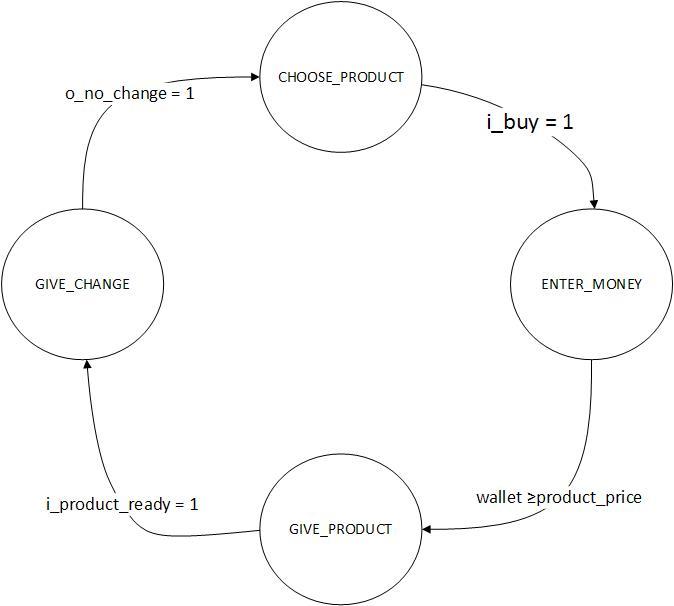
The state machine has 4 states in total: CHOOSE_PRODUCT, ENTER_MONEY, GIVE_PRODUCT, GIVE_CHANGE.
I think that from the names, in principle, it is clear what's what.
I also offer your attention to any diagram of this miracle:
→ Description on Verilog can be found here.
I would like to divide this section into two parts. In the first one I will give the structure of the testbench, I will describe each functional block of which it consists. The second discussion will deal with the so-called code and functional coverage and assertions.
Let's start with a picture that illustrates the structure of the testbench.
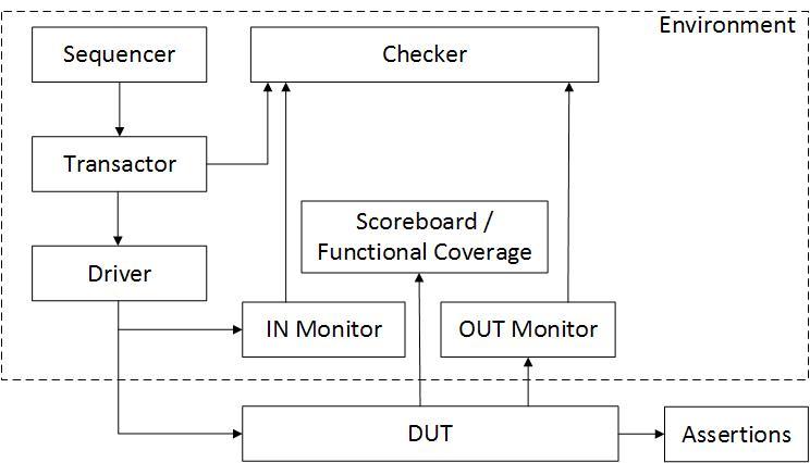
Consider each block separately:
DUT (design under test) - this block is the description of the state machine with one small modification in the form of a wrapper, which allows the testbench units to interact with each other using the interface .
In general, the interface is such a language design SystemVerilog, which allows you to group signals together and simplify the developer's robot. You can do a lot of cool things with it, which you can read about in the standard for the language and a bit in this article.
Reference to DUT
Assertions - here we are at the signal level to check how consistent the behavior of our design is with the device specification.
In this we are helped by such constructions as: assert , property , sequence . We can also include the results of testing the behavior of our model in the definition of functional coverage using the cover construction.
→ A reference to Assertions
Environment - it can be conventionally called a container in which all other blocks live that implement verification, or in other words, a software verification environment.
When describing it, use the Program construct. Why is it so difficult to answer, for me it is also a question for now. Perhaps this is due to the regions of the simulation simulator SystemVerilog, but this is still a guess.
→ A reference to the Environment
Inside the Environment , there are many other entities that just generate incentives for design, implement various verification scenarios, verify the accuracy of the output data and evaluate the code and functional coverage. So, let's go to them:
Sequencer is a block where scenarios are described, according to which verification will occur. These descriptions are fairly high-level and rely on methods provided by Transactor . What is remarkable here is that the workhorse of this block is usually the randsequence design. Its main task is to provide a convenient way to organize a script as a sequence of calls to Transactor methods. Here is the link where it is well explained how to use the randsequence .
→ But what I did (Sequencer)
Transactor is a block that implements methods that actually serve as the basis for scripts. At this stage, the same information is generated, which will be transmitted as input signals to our design. And here comes the power of SystemVerilog.
In SystemVerilog, you can make the values of class fields randomly generated. This is very useful because it allows you to significantly speed up verification. Actually, in order to make the field randomly generated, you need to use the rand or randc keyword .
But that is not all. Suppose you have created a variable of type int , but you need to ensure that the values that it accepts are defined by a strict range (for example, you can have only certain addresses on your bus). And on this account SystemVerilog has a present for you: a constraint design that allows you to restrict what properties your random variables will have. Example from the project:
Here I created the variable product_code which I limited to the interval [1; 8] using c_product_code .
But there is one thing, but. After creating an instance of a class, the variables rand and randc are not initialized by a random value. This happens when the built-in instance method randomize () is called.
Go back to Transactor . The use of rand fields, the randomize () method and its extensions randomize () with occurs naturally in Transactor . Unlike randomize () , randomize () with allows for its imposing additional restrictions on the rand field. More details about this can be found in the language standard SystemVerilog and here .
→ And of course Transactor
Driver is the only one who really works here. His task is to turn the information received from Transactor into design input signals. With him, everything is simple and clear. Therefore, I will tell you a little about the interface design.
These are not constructions that can be found in ordinary programming languages. Here the interface is more a design that allows you to group signals, regardless of their direction, as is convenient for the user. There are only three interface constructs in the project: dut_interface, vm_in_interface, vm_out_interface. The first is the synchronization and reset signal, the second is the vending_machine input, the third is its output. So, it all looks .
→ And of course - Driver
IN Monitor and OUT Monitor — these blocks read information that goes into and out of the DUT for further validation checks. Why read the information when entering the DUT , if it is stored in the Driver, you ask? Everything is simple to avoid errors in the driver Robot and all the above blocks.
→ IN and OUT Monitor
Checker is a block that performs the verification of the compliance of the reference data that is calculated on the basis of the data obtained from the IN Monitor and the data obtained from the OUT Monitor .
Scoreboard / Functional Coverage is the last block and is a hybrid of two separate blocks that perform different functions. The scoreboard itself should generate reference data and generate reports upon completion of the simulation, but in this project it is not very convenient to do this, since it is small. Functional Coverage by itself makes checking the coverage of all possible functions that are embedded in the device specification.
And here we come to the juice itself, how to do functional coverage . To do this, SystemVerilog has a special covergroup design. In each covergroup you define the so-called coverpoint , in which the binding to a specific signal or bus on which it is checked will be checked whether all possible data variations were obtained by the design and whether all possible data appeared on its outputs.
In general, access to the results of functional coverage occurs at runtime , so there are special functions that allow you to evaluate it later, anytime.
One of them is the built-in function $ get_coverage which returns a value from 0 to 100 calculated on the basis of all cover constructions ( cover , covergroup , coverpoint ).
In addition to accessing the runtime , the concept of functional coverage can also be obtained in graphical simulation environments (I can vouch for ModelSim so precisely).
Let's move on to code coverage . This indicator gives us an understanding of how much code we used was written and how complete our tests were. If for some reason your code coverage does not reach your acceptable level, then there are 2 options: write a test better, or your code is excessive. In any case, it will need to be fixed. True, it is worth mentioning separately that there are times when, as it were, the tests are good and the design code is good, but still the code coverage does not suit us, then we will have to exclude something from the check.
In general, what code coverage checks:
These, as well as other checks (checks of finite automata and the so-called FEC Condition ) give an idea of the project’s code coverage .
To enable the code coverage assessment, it is necessary to set the appropriate compiler settings for the file for which code coverage will be evaluated.
→ And, of course, I almost forgot (Scoreboard / Functional Coverage)
→ Well, the link to the entire project
Well, that's all. Thanks for attention. I hope you find this article for yourself in something useful.
Until new meetings.
In general, the basis of the publication is my course project, which was appreciated by my teacher with the proposal to make a publication on Habré.
The main thing I want to emphasize is the descriptions of typical multilayer testbench blocks and the application of some basic constructions of the SystemVerilog language and verification. The approach that I used is the so-called Open Verification Methodology (OVM) with changes that simplified the development of the project and were convenient for me personally.
')
So let's go!
The specification of the device and its operation
The material that follows will be difficult to call the device specification, but an attempt has been made. And that's what came out of it.
The device being verified is Moore's finite state machine, the purpose of which is: control of the vending machine.
Device interface: 7 input signals / buses and 6 output signals / buses. The purpose of the signals, their width and direction for convenience are presented in a table.
| Signal / Bus Name | Direction | Digit | Purpose |
|---|---|---|---|
| i_clk | input | one | Sync signal |
| i_rst_n | input | one | Active Low Reset Signal |
| i_money | input | four | The tire on which codes of denominations of monetary units are transferred |
| i_money_valid | input | one | Signal of code validity on the i_money bus |
| i_product_code | input | four | The bus on which pass the codes of goods |
| i_buy | input | one | Purchase Confirmation Signal |
| i_product_ready | input | one | Signal of product readiness (input, because I have accepted that another device is engaged in the preparation of the product) |
| o_product_code | output | four | Item code to be issued to the buyer |
| o_product_valid | output | one | Signal of validity of information on the bus o_product_code |
| o_busy | output | one | Signal that the state machine is busy processing the current order |
| o_change_denomination_code | output | four | Delivery, or rather codes of denominations of monetary units |
| o_change_valid | output | one | Signal of validity on the bus o_change_denomination_code |
| o_no_change | output | one | Delivery End Signal |
The state machine has 4 states in total: CHOOSE_PRODUCT, ENTER_MONEY, GIVE_PRODUCT, GIVE_CHANGE.
I think that from the names, in principle, it is clear what's what.
But if it is not clear, then it should be explained
CHOOSE_PRODUCT: In this state, the state machine accepts the product code and waits for confirmation of the purchase.
ENTER_MONEY: Here, mi, we give the machine a coin in the form of currency denomination codes. The transition to the next state takes place immediately after the money in the wallet of the machine has nothing less than is needed to purchase the goods.
GIVE_PRODUCT: Here we count the change and pass the code of the product to be prepared by the "abstract device to the performer." The transition to the next state occurs after the receipt of the corresponding signal of product readiness from the "abstract artist".
GIVE_CHENGE: Give change and go into standby mode, that is, CHOOSE_PRODUCT.
I also offer your attention to any diagram of this miracle:
→ Description on Verilog can be found here.
Actually verification
I would like to divide this section into two parts. In the first one I will give the structure of the testbench, I will describe each functional block of which it consists. The second discussion will deal with the so-called code and functional coverage and assertions.
Testbench structure
Let's start with a picture that illustrates the structure of the testbench.
Consider each block separately:
DUT (design under test) - this block is the description of the state machine with one small modification in the form of a wrapper, which allows the testbench units to interact with each other using the interface .
In general, the interface is such a language design SystemVerilog, which allows you to group signals together and simplify the developer's robot. You can do a lot of cool things with it, which you can read about in the standard for the language and a bit in this article.
Reference to DUT
Assertions - here we are at the signal level to check how consistent the behavior of our design is with the device specification.
In this we are helped by such constructions as: assert , property , sequence . We can also include the results of testing the behavior of our model in the definition of functional coverage using the cover construction.
→ A reference to Assertions
Environment - it can be conventionally called a container in which all other blocks live that implement verification, or in other words, a software verification environment.
When describing it, use the Program construct. Why is it so difficult to answer, for me it is also a question for now. Perhaps this is due to the regions of the simulation simulator SystemVerilog, but this is still a guess.
→ A reference to the Environment
Inside the Environment , there are many other entities that just generate incentives for design, implement various verification scenarios, verify the accuracy of the output data and evaluate the code and functional coverage. So, let's go to them:
Sequencer is a block where scenarios are described, according to which verification will occur. These descriptions are fairly high-level and rely on methods provided by Transactor . What is remarkable here is that the workhorse of this block is usually the randsequence design. Its main task is to provide a convenient way to organize a script as a sequence of calls to Transactor methods. Here is the link where it is well explained how to use the randsequence .
→ But what I did (Sequencer)
Transactor is a block that implements methods that actually serve as the basis for scripts. At this stage, the same information is generated, which will be transmitted as input signals to our design. And here comes the power of SystemVerilog.
In SystemVerilog, you can make the values of class fields randomly generated. This is very useful because it allows you to significantly speed up verification. Actually, in order to make the field randomly generated, you need to use the rand or randc keyword .
But that is not all. Suppose you have created a variable of type int , but you need to ensure that the values that it accepts are defined by a strict range (for example, you can have only certain addresses on your bus). And on this account SystemVerilog has a present for you: a constraint design that allows you to restrict what properties your random variables will have. Example from the project:
rand logic [ 3:0] product_code; constraint c_product_code { product_code inside { [ 1 : 8 ] }; } Here I created the variable product_code which I limited to the interval [1; 8] using c_product_code .
But there is one thing, but. After creating an instance of a class, the variables rand and randc are not initialized by a random value. This happens when the built-in instance method randomize () is called.
Go back to Transactor . The use of rand fields, the randomize () method and its extensions randomize () with occurs naturally in Transactor . Unlike randomize () , randomize () with allows for its imposing additional restrictions on the rand field. More details about this can be found in the language standard SystemVerilog and here .
→ And of course Transactor
Driver is the only one who really works here. His task is to turn the information received from Transactor into design input signals. With him, everything is simple and clear. Therefore, I will tell you a little about the interface design.
These are not constructions that can be found in ordinary programming languages. Here the interface is more a design that allows you to group signals, regardless of their direction, as is convenient for the user. There are only three interface constructs in the project: dut_interface, vm_in_interface, vm_out_interface. The first is the synchronization and reset signal, the second is the vending_machine input, the third is its output. So, it all looks .
→ And of course - Driver
IN Monitor and OUT Monitor — these blocks read information that goes into and out of the DUT for further validation checks. Why read the information when entering the DUT , if it is stored in the Driver, you ask? Everything is simple to avoid errors in the driver Robot and all the above blocks.
→ IN and OUT Monitor
Checker is a block that performs the verification of the compliance of the reference data that is calculated on the basis of the data obtained from the IN Monitor and the data obtained from the OUT Monitor .
Scoreboard / Functional Coverage is the last block and is a hybrid of two separate blocks that perform different functions. The scoreboard itself should generate reference data and generate reports upon completion of the simulation, but in this project it is not very convenient to do this, since it is small. Functional Coverage by itself makes checking the coverage of all possible functions that are embedded in the device specification.
And here we come to the juice itself, how to do functional coverage . To do this, SystemVerilog has a special covergroup design. In each covergroup you define the so-called coverpoint , in which the binding to a specific signal or bus on which it is checked will be checked whether all possible data variations were obtained by the design and whether all possible data appeared on its outputs.
In general, access to the results of functional coverage occurs at runtime , so there are special functions that allow you to evaluate it later, anytime.
One of them is the built-in function $ get_coverage which returns a value from 0 to 100 calculated on the basis of all cover constructions ( cover , covergroup , coverpoint ).
In addition to accessing the runtime , the concept of functional coverage can also be obtained in graphical simulation environments (I can vouch for ModelSim so precisely).
Let's move on to code coverage . This indicator gives us an understanding of how much code we used was written and how complete our tests were. If for some reason your code coverage does not reach your acceptable level, then there are 2 options: write a test better, or your code is excessive. In any case, it will need to be fixed. True, it is worth mentioning separately that there are times when, as it were, the tests are good and the design code is good, but still the code coverage does not suit us, then we will have to exclude something from the check.
In general, what code coverage checks:
- Statement - lines executed and not executed during simulation
- Branches - checks the execution of constructions if..else, case
- Condition - checks for logical conditions whose results must be True or False
- Toggle - checks logical transitions from 0 to 1 and vice versa
These, as well as other checks (checks of finite automata and the so-called FEC Condition ) give an idea of the project’s code coverage .
To enable the code coverage assessment, it is necessary to set the appropriate compiler settings for the file for which code coverage will be evaluated.
→ And, of course, I almost forgot (Scoreboard / Functional Coverage)
→ Well, the link to the entire project
Well, that's all. Thanks for attention. I hope you find this article for yourself in something useful.
Until new meetings.
Source: https://habr.com/ru/post/319730/
All Articles