Real-time BeagleBone: Using High-Speed Pins
Hello, dear habravchane! I have long been a reader of Habr, but still could not find a decent topic for publication. And now, finally, having thoroughly gone through Habr and GT, I was surprised at the lack of publications on the Programmable Real-Time Subsystem ( PRU-ICSS ) of the TI Sitara TM processor line.
The most popular and affordable debug board with an AM335x processor is the so-called “single-board” BeagleBone Black (White, Green). And it is the presence of the PRU that makes BeagleBone the most preferable for use in hardware projects as compared to other budget single-server * Pi . In addition, in some cases, BBB-PRU can quite effectively replace a bunch of PC - MK - FPGA .
')
This article provides a brief overview of the PRU subsystem and the modes of operation of high-speed I / O ports, a step-by-step example of the initialization of high-speed output ports (Enhanced GPIO) and an assessment of their performance.
Introduction
I’ll make a reservation at once that I’ll not dwell on the characteristics and settings of the BeagleBone itself, since these topics are fairly well covered on the Internet, I’ll just give the most useful, in my opinion, resources at the end. And I will concentrate directly on the PRU-ICSS subsystem.
Similar PRU solutions from among the popular ones have been found only for Intel Edison (by the way, a tutorial on this topic). But at a similar price, Edison is inferior in performance and performance.
IMPORTANT! Not all PRU modes of operation described below and not fully implemented with BeagleBone due to the physical limitations of the board topology.
A significant part of the materials presented in the publication is a translation, adaptation, modification, or combination of resources, given in useful sources at the end of the article.
So, what is the real-time subsystem?
PRU ICSS Overview
PRU-ICSS consists of two 32-bit cores with a RISC architecture and operating at 200 MHz. Each core has its own memory area, as well as a shared memory area with Linux, it can use general-purpose pins located on the P8-P9 connectors and form interrupts.
The PRU is an important addition to the entire BeagleBone platform, allowing you to provide support for applications with tight time constraints. But it is worth noting that the PRU is not a hardware accelerator, allowing to increase the speed of Linux-based applications. The PRU can be assigned to perform certain functions and tasks, such as implementing software high-speed data transfer protocols, including non-standard ones, or digital processing of sensor signals in real time. You can also simply implement additional hardware, such as the sixth UART ttyO6.
PRU architecture
I will not delve into the translation of the manuals, I will mention the main characteristics of the system and comment on some of the slides from the presentations and schemes from the manuals .
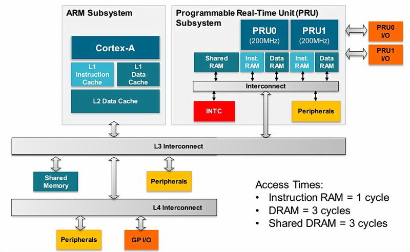
The main advantage of PRU is the short access time to local memory and peripherals. In the clock cycles of the reference frequency, it is even lower than that of the ARM subsystem. A more detailed description of write / read delays is provided here .
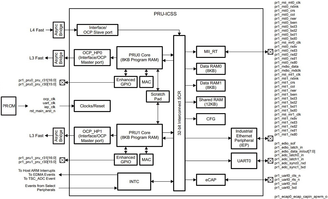
The PRU subsystem includes the following units:
- Two PRU cores, each includes:
- 8KB memory instructions;
- 8KB of data memory;
- High-speed OCP bus interface for access to memory and ARM peripherals;
- I / O ports ( eGPIO ) with support for asynchronous capture and serial output;
- Accumulative multiplier ( MAC );
- High-speed temporary memory ( Scratchpad memory ):
- 3 blocks, in each 30 32-bit registers;
- Direct access allows fast synchronization between PRU cores;
- One Interrupt Controller (INTC):
- Receive up to 64 external events;
- 10 interrupt channels;
- Hardware prioritization of events;
- One set of industrial Ethernet peripherals:
- One timer with 10 capture events and 8 comparisons;
- Two synchronization signals;
- Two 16-bit watchdog timers;
- Digital I / O ports;
- 12KB general purpose memory;
- Formation of 16 program events;
- One dual port MII Ethernet module;
- One MDIO port;
- One UART transceiver with a clock frequency of 192 MHz;
- One capture module ( ECAP );
- Supports flexible power management;
Now let's take a closer look at the structure of high-speed I / O ports, which is directly the topic of the lesson below and the subject of study.
Management of input and output ports is carried out using the registers R31 and R30, respectively. It is noteworthy that the register R31 is also used to form a system interrupt. Thus, writing to R31 generates an interrupt, and reading from the register returns information about the state of the input ports (GPI) and the interrupt controller (INTC).
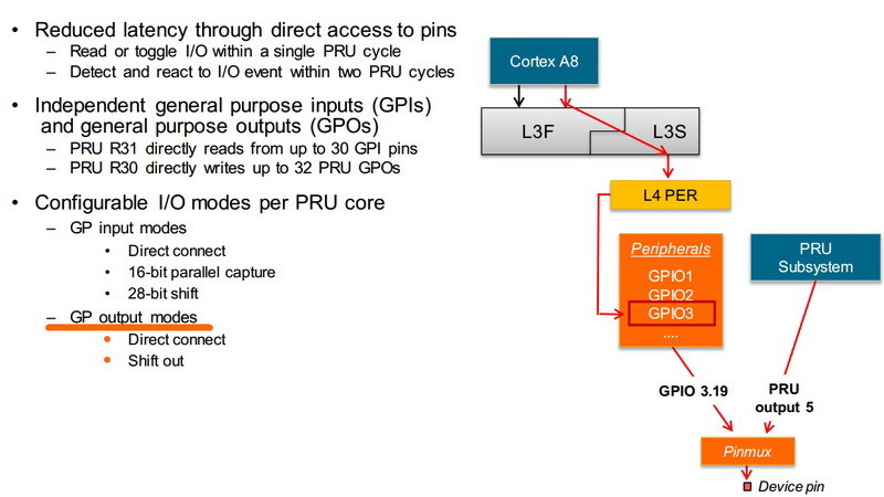
The high speed of the I / O ports is provided by direct PRU access, unlike the ARM core, which has access to GPIO through several levels of connections.
GPIO Modes
Modes are set by setting the corresponding bits in the CFG configuration register. Live mode is the default mode and does not require additional settings.
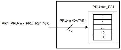
Input ports (GPI - R31) have 4 operation modes:
- Live:
- The PRU <n> _DATAIN register (pru <n> _r31_status [16: 0]) is connected directly to the corresponding PRU <n>
- Each PRU has independent input ports, so the total is 34;
- GPI Live Connection
- 16-bit parallel capture:
- The PRU <n> _DATAIN register (pru <n> _r31_status [16: 0]) captures data on the positive or negative edge of the clock frequency generated in the PRU <n> _CLOCK register (pru <n> _r31_status [16]);
- Parallel capture circuit
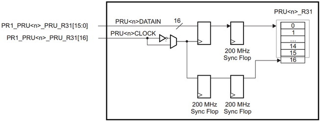
- The PRU <n> _DATAIN register (pru <n> _r31_status [16: 0]) captures data on the positive or negative edge of the clock frequency generated in the PRU <n> _CLOCK register (pru <n> _r31_status [16]);
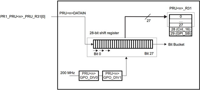
- Shift 28-bit input register:
- Register PRU <n> _DATAIN (pru <n> _r31_status [0]) captures and then shifts;
- The sampling rate is determined by the corresponding value of the slips in the CGF configuration register;
- Shift register pattern
- MII_RT mode:
- Register mii_rt_r31_status [29: 0] is under the control of the module MII_RT;
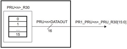
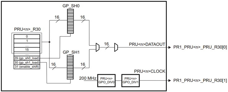
Output ports (GPO - R30) have 2 operation modes:
- Live:
- The PRU <n> _DATAOUT register (pru <n> _r30 [15: 0]) is connected directly to the corresponding PRU <n>
- Each PRU has independent output ports, so the total is 32;
- GPO Direct Power On Scheme
- Shift Output Register:
- The PRU <n> _DATAOUT register (pru <n> _r30 [0]) outputs and then shifts along the positive edge of the clock frequency generated in the PRU <n> _CLOCK register (pru <n> _r30 [1]);
- The sampling rate is determined by the corresponding value of the slips in the CGF configuration register;
- In this mode, double buffering is implemented using the 16-bit shadow registers gpo_sh0 and gpo_sh1;
- Each shadow register has an independent load control signal pru <n> _r30 [29:30] (PRU <n> _LOAD_GPO_SH [0: 1]);
- The issuance of values begins after setting the pru <n> _r30 [31] bit (PRU <n> _ENABLE_SHIFT) to 1;
- If you do not update the values of the shadow registers, then the cyclic output of the predefined values will continue;
- Values are terminated when the pru <n> _r30 [31] bit (PRU <n> _ENABLE_SHIFT) is reset to 0;
- Shift register pattern
It is worth noting that the PRU can also access normal I / O ports and other peripherals of the ARM core via the OCP bus, but this will take longer.
Development under PRU
To create a program under PRU, the following actions are required:
- Install the PRU-ICSS package (if not pre-installed);
- Create a description of the device tree of the used peripherals and PRUs, compile and download it;
- Write a program for PRU (* .p) and compile it (* .bin);
- Write a loading and control program (*. C) for the PRU program and compile it;
The PRU-ICSS package serves as a means of downloading applications from Linux to the PRU and consists of two sections: a low-level kernel driver and user libraries. The low-level kernel driver (uio_pru) provides the interaction of the PRU core with the PRUSSDRV user library and takes over the functions of powering the PRU, initializing the PRU clock, allocating memory for the PRU, and registering the PRU interrupts. The PRUSSDRV library, in turn, allows you to start and stop the PRU, provides PRU access to peripherals and external memory, and manages PRU interrupts. Also, the PRU-ICSS package includes the PRU assembler compiler - pasm.
PRU-ICSS package software stack:

Thus, the program * .c under Linux using the functions of the PRUSSDRV library loads the executable file (* .bin) into the PRU, creates shared memory areas, sends and receives interrupts.
Separately, it is worth mentioning that for PRU, TI has released the prudebug debugger and the C compiler .
A compact and informative description of the instruction set can be found here .
Areas of possible use
As noted earlier, the main task of the PRU is to unload the main ARM core by performing strictly time-limited tasks. Such tasks can be the implementation of data transfer protocols or digital signal processing units. So on BeagleBone PRU you can implement up to 25 PWM channels or 4 additional software UART. The most successful projects demonstrating the power of PRU are BeagleLogic , MachineKit and LEDscape .
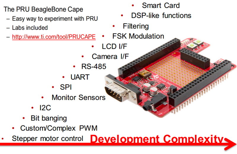
Examples of use of PRU-cape:
PRU installation
Let's start, finally, the practical part.
So, I will experiment on the existing Beaglebone Black A5C revision. I use the Linux image bone-debian-7.8-lxde-4gb-armhf-2015-03-01-4gb.img.xz , loaded from an external SD memory card. To access the BBB I use SSH PuTTY, for sharing WinSCP files.
root@beaglebone:~# uname -a Linux beaglebone 3.8.13-bone70 #1 SMP Fri Jan 23 02:15:42 UTC 2015 armv7l GNU/Linux In the latest versions of the kernel, the remoteproc framework is used by default for PRU programming , but I have not yet mastered it, so we will use the PRUSSDRV library described earlier. To make this possible, we include the module:
root@beaglebone:~# modprobe uio_pruss Make sure the other necessary components are preinstalled.
root@beaglebone:~# ls -a /usr/include | grep pruss pruss_intc_mapping.h prussdrv.h root@beaglebone:~# ls -a /usr/lib | grep pruss libprussdrv.a libprussdrv.so libprussdrvd.a libprussdrvd.so root@beaglebone:~# pasm PRU Assembler Version 0.86 Copyright (C) 2005-2013 by Texas Instruments Inc. Usage: pasm [-V#EBbcmLldz] [-Idir] [-Dname=value] [-Cname] InFile [OutFileBase] ... root@beaglebone:~# lsmod | grep pru uio_pruss 4066 0 Perform preliminary settings by setting the necessary environment variables in autoload:
echo "export SLOTS=/sys/devices/bone_capemgr.*/slots" >> ~/.profile #echo "export SLOTS=/sys/devices/platform/bone_capemgr/slots" >> ~/.profile # 4 echo "export PINS=/sys/kernel/debug/pinctrl/44e10800.pinmux/pins" >> ~/.profile echo "export PINGROUPS=/sys/kernel/debug/pinctrl/44e10800.pinmux/pingroups" >> ~/.profile source .profile HDMI / EMMC Disable
Almost all PRU peripherals are routed to ports whose main function is HDMI / EMMC. Therefore, for successful interaction of the PRU with the outside world, it is necessary to disable the initialization of HDMI / EMMC.
For the image used, this is done quite simply - it is only necessary to uncomment the required line in / boot / uEnv.txt. Therefore, we edit it
nano /boot/uEnv.txt , so that in the end it’s like this: ... ##Disable HDMI/eMMC cape_disable=capemgr.disable_partno=BB-BONELT-HDMI,BB-BONELT-HDMIN,BB-BONE-EMMC-2G ... GPIO: direct mode
Using the informative tables of the P8 and P9 connectors, you can find out that BeagleBone has 8 high-speed output ports for PRU0 and 14 for PRU1. As described earlier , you must first disable HDMI / EMMC and configure the pins in the desired mode. Since I want to squeeze more out of the BBB, we will work with PRU1 and configure the pins pr1_pru1_pru_r30 [0:13]. Also, we still have one unused input pr1_pru1_pru_r31_16, located on connector P9.26. It is used to run the program on the external button.
The best example of how to demonstrate the operation of the ports of general purpose PRU, in my opinion, will be the implementation of the programmable hardware delay function for an external event. We will transmit the delay using a user program under linux through a shared area of memory. The PRU directly implements a hardware delay and outputs its value, namely the lower 14 bits, to the available outputs.
Thus, the following program algorithm appears:
- Run the user program with the desired delay as an argument;
- The program initializes the PRU, passes the delay value, and starts the PRU routine;
- The subroutine PRU waits for an external event (button press);
- After an event is detected, the specified delay counts;
- Notifies user program of completion through an interrupt;
- The user program receives a subroutine shutdown interrupt;
- After that, deactivates the PRU and terminates itself;
Direct GPO device tree overlays
So, to implement the conceived program, it is necessary to configure 14 BBB ports for output and 1 port for input, as well as directly launch the PRU subsystem.
Based on the examples from github, I compiled the following description of the device tree:
PRU_DGPO-00A0.dts
/dts-v1/; /plugin/; / { compatible = "ti,beaglebone", "ti,beaglebone-black"; /* identification */ part-number = "PRU_DGPO"; version = "00A0"; /* state the resources this cape uses */ exclusive-use = /* PRU1 Direct Output */ "P8.20", /* pru1: pr1_pru1_pru_r30_13 */ "P8.21", /* pru1: pr1_pru1_pru_r30_12 */ "P8.28", /* pru1: pr1_pru1_pru_r30_10 */ "P8.27", /* pru1: pr1_pru1_pru_r30_8 */ "P8.30", /* pru1: pr1_pru1_pru_r30_11 */ "P8.29", /* pru1: pr1_pru1_pru_r30_9 */ "P8.40", /* pru1: pr1_pru1_pru_r30_7 */ "P8.39", /* pru1: pr1_pru1_pru_r30_6 */ "P8.42", /* pru1: pr1_pru1_pru_r30_5 */ "P8.41", /* pru1: pr1_pru1_pru_r30_4 */ "P8.44", /* pru1: pr1_pru1_pru_r30_3 */ "P8.43", /* pru1: pr1_pru1_pru_r30_2 */ "P8.46", /* pru1: pr1_pru1_pru_r30_1 */ "P8.45", /* pru1: pr1_pru1_pru_r30_0 */ /* PRU1 Direct Input */ "P9.26", /* pru1: pr1_pru1_pru_r31_16 */ /* the hardware ip uses */ "pru1"; fragment@0 { target = <&am33xx_pinmux>; __overlay__ { pru_pru_pins: pinmux_pru_pru_pins { // The PRU pin modes pinctrl-single,pins = < 0x084 0x0D /* lcd_pclk.pr1_pru1_pru_r30_13, MODE5 | OUTPUT | PRU */ 0x080 0x0D /* lcd_pclk.pr1_pru1_pru_r30_12, MODE5 | OUTPUT | PRU */ 0x0e8 0x0D /* lcd_pclk.pr1_pru1_pru_r30_10, MODE5 | OUTPUT | PRU */ 0x0e0 0x0D /* lcd_vsync.pr1_pru1_pru_r30_8, MODE5 | OUTPUT | PRU */ 0x0ec 0x0D /* lcd_ac_bias_en.pr1_pru1_pru_r30_11, MODE5 | OUTPUT | PRU */ 0x0e4 0x0D /* lcd_hsync.pr1_pru1_pru_r30_9, MODE5 | OUTPUT | PRU */ 0x0bc 0x0D /* lcd_data7.pr1_pru1_pru_r30_7, MODE5 | OUTPUT | PRU */ 0x0b8 0x0D /* lcd_data6.pr1_pru1_pru_r30_6, MODE5 | OUTPUT | PRU */ 0x0b4 0x0D /* lcd_data5.pr1_pru1_pru_r30_5, MODE5 | OUTPUT | PRU */ 0x0b0 0x0D /* lcd_data4.pr1_pru1_pru_r30_4, MODE5 | OUTPUT | PRU */ 0x0ac 0x0D /* lcd_data3.pr1_pru1_pru_r30_3, MODE5 | OUTPUT | PRU */ 0x0a8 0x0D /* lcd_data2.pr1_pru1_pru_r30_2, MODE5 | OUTPUT | PRU */ 0x0a4 0x0D /* lcd_data1.pr1_pru1_pru_r30_1, MODE5 | OUTPUT | PRU */ 0x0a0 0x0D /* lcd_data0.pr1_pru1_pru_r30_0, MODE5 | OUTPUT | PRU */ 0x180 0x36 /* uart1_rxd.pr1_pru1_pru_r31_16, MODE6 | INPUT | PRU */ >; }; }; }; fragment@1 { target = <&ocp>; __overlay__ { test_helper: helper { compatible = "bone-pinmux-helper"; pinctrl-names = "default"; pinctrl-0 = <&pru_pru_pins>; status = "okay"; }; }; }; fragment@2 { // Enable the PRUSS target = <&pruss>; __overlay__ { status = "okay"; }; }; }; Next, this file must be compiled, copied to / lib / firmware and downloaded:
echo "Compiling the overlay from .dts to .dtbo" dtc -O dtb -o PRU_DGPO-00A0.dtbo -b 0 -@ PRU_DGPO-00A0.dts echo "Copy PRU_DGPO-00A0.dtbo to /lib/firmware" cp PRU_DGPO-00A0.dtbo /lib/firmware echo "Loading overlay:" sh -c "echo 'PRU_DGPO' > $SLOTS" Then you should check the boot process.
In a successful case, it should be like this:
root@beaglebone:~# dmesg | tail [12566.485091] bone-capemgr bone_capemgr.9: slot #7: generic override [12566.485149] bone-capemgr bone_capemgr.9: bone: Using override eeprom data at slot 7 [12566.485197] bone-capemgr bone_capemgr.9: slot #7: 'Override Board Name,00A0,Override Manuf,PRU_DGPO' [12566.485506] bone-capemgr bone_capemgr.9: slot #7: Requesting part number/version based 'PRU_DGPO-00A0.dtbo [12566.485554] bone-capemgr bone_capemgr.9: slot #7: Requesting firmware 'PRU_DGPO-00A0.dtbo' for board-name 'Override Board Name', version '00A0' [12566.492347] bone-capemgr bone_capemgr.9: slot #7: dtbo 'PRU_DGPO-00A0.dtbo' loaded; converting to live tree [12566.494050] bone-capemgr bone_capemgr.9: slot #7: #3 overlays [12566.555682] bone-capemgr bone_capemgr.9: slot #7: Applied #3 overlays. root@beaglebone:~# cat $SLOTS 0: 54:PF--- 1: 55:PF--- 2: 56:PF--- 3: 57:PF--- 4: ff:PO-- Bone-LT-eMMC-2G,00A0,Texas Instrument,BB-BONE-EMMC-2G 5: ff:PO-- Bone-Black-HDMI,00A0,Texas Instrument,BB-BONELT-HDMI 6: ff:PO-- Bone-Black-HDMIN,00A0,Texas Instrument,BB-BONELT-HDMIN 7: ff:POL Override Board Name,00A0,Override Manuf,PRU_DGPO root@beaglebone:~# cat $PINS | grep 00d pin 32 (44e10880) 0000000d pinctrl-single pin 33 (44e10884) 0000000d pinctrl-single pin 40 (44e108a0) 0000000d pinctrl-single pin 41 (44e108a4) 0000000d pinctrl-single pin 42 (44e108a8) 0000000d pinctrl-single pin 43 (44e108ac) 0000000d pinctrl-single pin 44 (44e108b0) 0000000d pinctrl-single pin 45 (44e108b4) 0000000d pinctrl-single pin 46 (44e108b8) 0000000d pinctrl-single pin 47 (44e108bc) 0000000d pinctrl-single pin 56 (44e108e0) 0000000d pinctrl-single pin 57 (44e108e4) 0000000d pinctrl-single pin 58 (44e108e8) 0000000d pinctrl-single pin 59 (44e108ec) 0000000d pinctrl-single root@beaglebone:~# cat $PINS | grep 036 pin 96 (44e10980) 00000036 pinctrl-single To learn more about the settings of the device tree of the latest Debian releases, I recommend contacting here .
In general, the Linux device tree is a separate topic that requires in-depth consideration. Those interested can start exploring Device Tree here and here .
User program
As mentioned earlier, the main tasks of the user program are:
- Initializing PRU;
- Data exchange with PRU through a shared memory area;
- Run subroutine PRU;
- Formation and processing of interruptions and PRU events;
Parallel_output.c:
#include <stdio.h> #include <stdlib.h> #include <prussdrv.h> #include <pruss_intc_mapping.h> #define PRU_NUM 1 // using PRU1 for these examples int main (int argc, char* argv[]) { unsigned int ret; if(getuid()!=0){ printf("You must run this program as root. Exiting.\n"); exit(EXIT_FAILURE); } if(argc!=2) { printf("Usage is Parralel_output and integer number of delay \n"); printf(" eg ./Parralel_output 100\n"); return 2; } char *p; unsigned int cyc = (unsigned int) strtol(argv[1], &p, 10); printf("Delay for %d cycles\n", cyc); // Initialize structure used by prussdrv_pruintc_intc // PRUSS_INTC_INITDATA is found in pruss_intc_mapping.h tpruss_intc_initdata pruss_intc_initdata = PRUSS_INTC_INITDATA; // Allocate and initialize memory prussdrv_init (); ret = prussdrv_open(PRU_EVTOUT_0); if (ret) { printf("prussdrv_open open failed\n"); return (ret); } // Map PRU's interrupts prussdrv_pruintc_init(&pruss_intc_initdata); // Write a number of cycles into PRU1 Data RAM0 prussdrv_pru_write_memory(PRUSS0_PRU1_DATARAM , 0, &cyc, 4); // Load and execute the PRU program on the PRU prussdrv_exec_program (PRU_NUM, "./Parallel_output.bin"); // Wait for event completion from PRU, returns the PRU_EVTOUT_0 number int n = prussdrv_pru_wait_event (PRU_EVTOUT_0); printf("PRU program completed, event number %d.\n", n); // Disable PRU and close memory mappings prussdrv_pru_disable(PRU_NUM); prussdrv_exit (); return EXIT_SUCCESS; } Compile:
gcc Parallel_output.c -o Parallel_output -lpthread -lprussdrv PRU subroutine
PASM assembler is used to write the PRU subroutine. The subroutine runs on one of the two PRU cores independently of Linux. PRU and Linux are synchronized via events and interrupts.
In addition to the algorithm described above, we will add a few more instructions to the subroutine in order to estimate their execution time.
Parallel_output.p:
.origin 0 // start of program in PRU memory .entrypoint START // program entry point (for a debugger) #define PRU0_R31_VEC_VALID 32 // allows notification of program completion #define PRU_EVTOUT_0 3 // the event number that is sent back START: WBC r31.t16 // wait bit clear - ie, button press // Toggle 4 times Parallel output pins MOV r30, 0xffff MOV r30, 0x0000 MOV r30, 0xffff MOV r30, 0x0000 LBCO r30, C24, 0, 4 // load PRU1 Data RAM into r30 (use c24 const addr) CYCLE: SUB r30, r30, 1 // Decrement REG30 by 1 - ie, parallel output current value on pins QBNE CYCLE, r30, 0 // Loop to CYCLE, unless REG30=0 END: // notify the calling app that finished MOV R31.b0, PRU0_R31_VEC_VALID | PRU_EVTOUT_0 HALT // halt the pru program Compile:
pasm -b Parallel_output.p Run PRU and performance evaluation
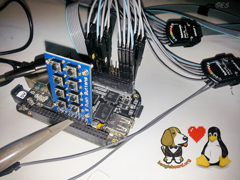
In order to estimate the speed of the PRU instructions, I will use a Tektronix MSO4032 350 MHz oscilloscope with a 16-channel logic analyzer having a resolution of 2 ns.
Photo system complete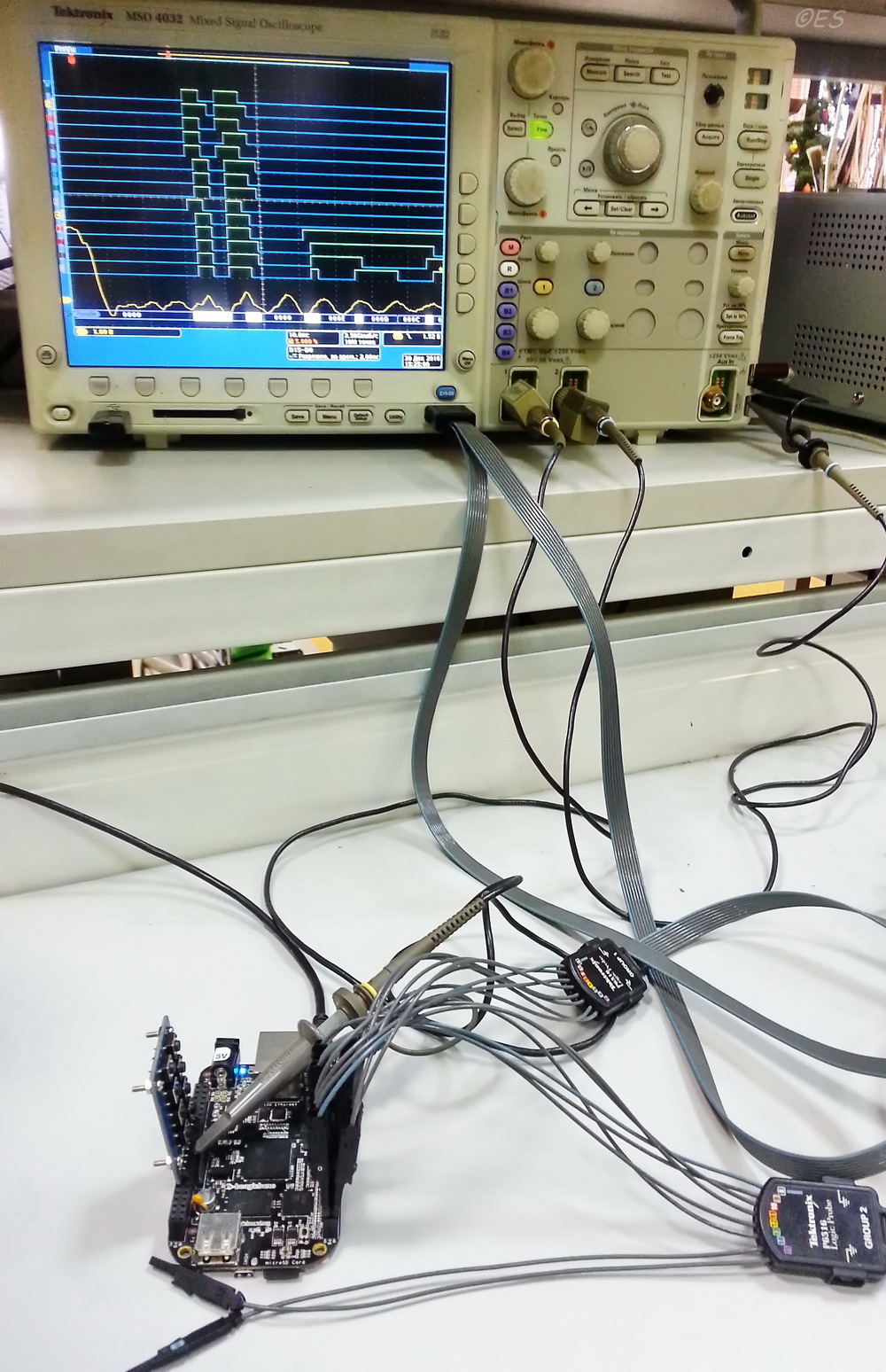
Finally, run the program:
root@beaglebone:/home/debian/Desktop/Direct-GPO# ./Parallel_output 15 Delay for 15 cycles PRU program completed, event number 1. Since the delay cycle includes 2 instructions (SUB and QBNE), each for 5 ns, the hardware delay will be arg * 10 ns . For the example above, the delay should be 150 ns. Measurements are taken without taking into account test initial instructions.
For clarity, the instructions are superimposed on the waveform:
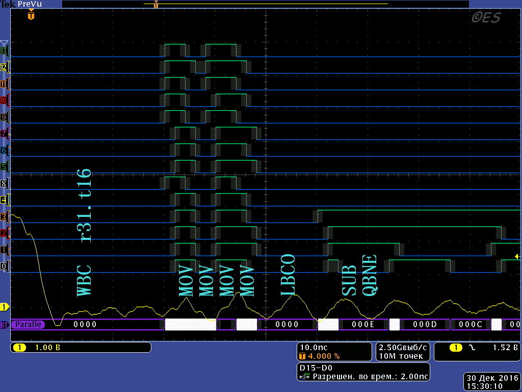
As you can see, the execution time of the MOV instruction within the error limits due to the resolution of the logic analyzer is 2 ns, and it fits well with the stated 5 ns. All 14 pins and 1 input are involved, as planned.
Execution of the WBC instruction - waiting for an event - takes ~ 25 ns, but this time is constant and it will not be difficult to take into account if necessary.
The following are oscillograms for different values of the arguments, the delay measurement is made using the oscilloscope cursors.
Oscillogram for 150 ns delay

root@beaglebone:~# ./Parallel_output 1515 µs delay waveform

root@beaglebone:~# ./Parallel_output 1500Oscillogram for a delay of 159.23 μs
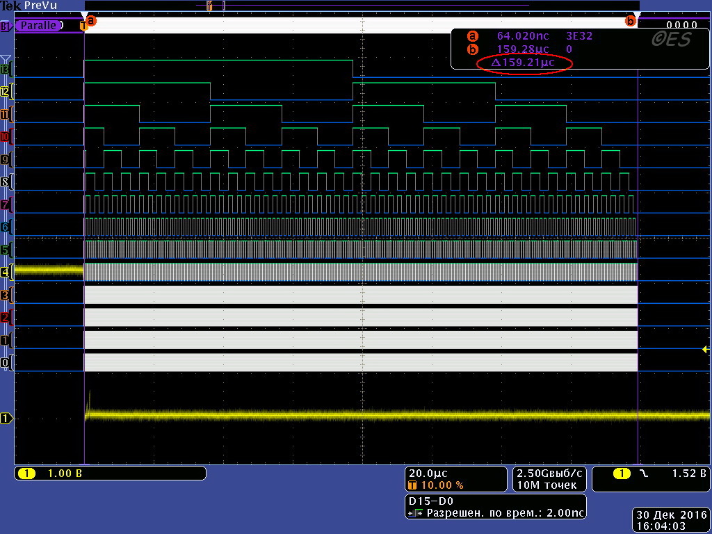
15923 is just a random number, close to 2 ^ 14, to tap into all the conclusions.
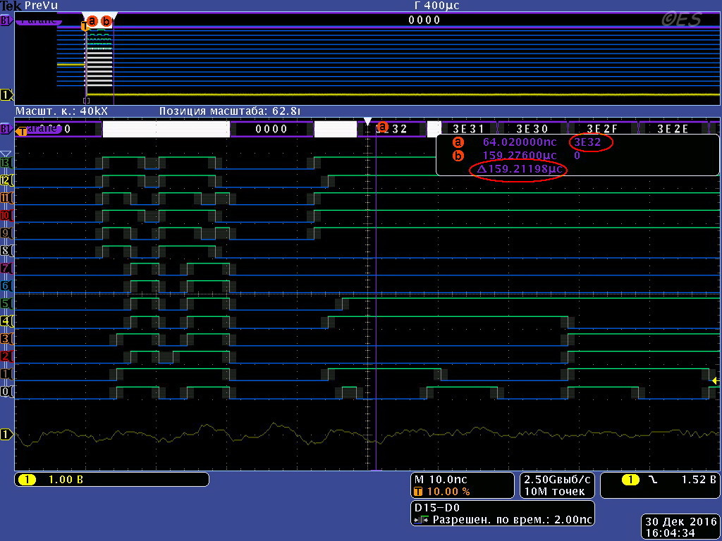
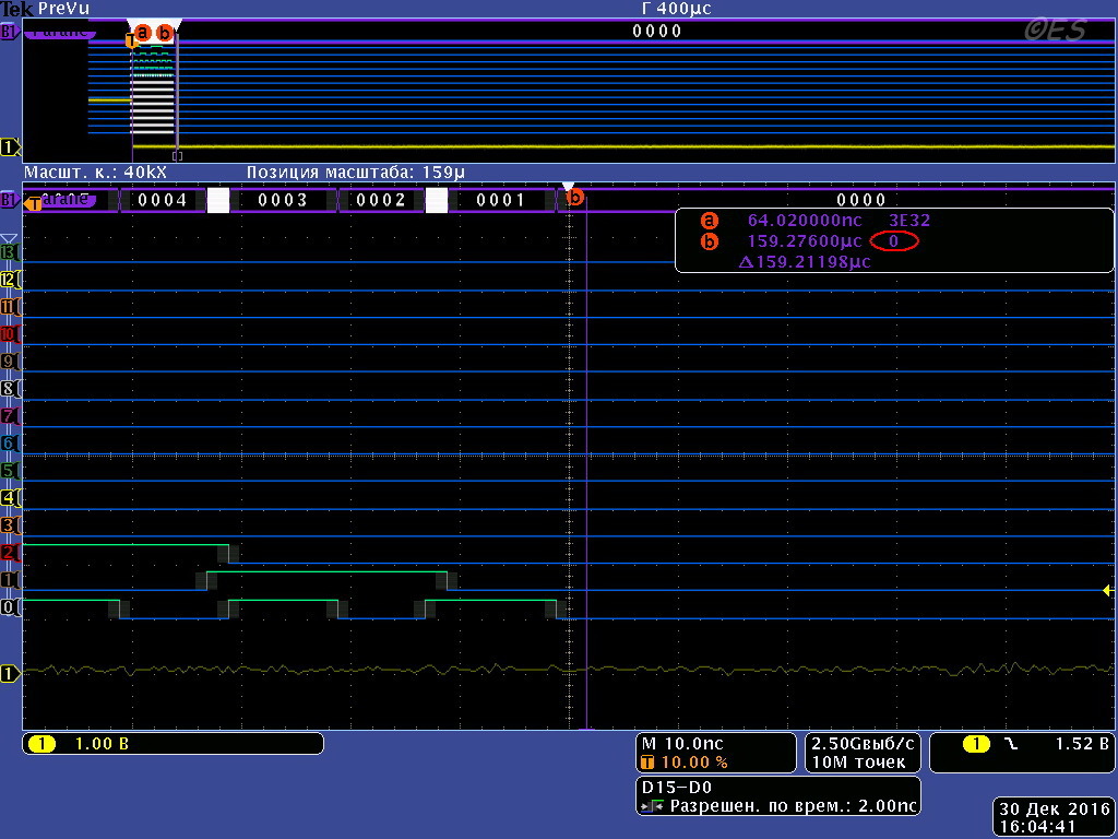
root@beaglebone:~# ./Parallel_output 1592315923 is just a random number, close to 2 ^ 14, to tap into all the conclusions.
hex2dec('3E32') = 15922.Results
Thus, using the above example, the capabilities of the BeagleBone PRU in terms of signal generation with a resolution of up to 5ns on 14 pins simultaneously are demonstrated, the basic principles of PRU control and configuration, as well as the PRU software model are considered.
Sources can be found here .
Useful sources
Much of the examples and principles of work are taken from the materials of Derek Molloy:
- Directly his site ;
- BeagleBone playlist ;
- The site of his book on BB with examples;
- Repository ;
Thank you so much for all this!
→ An interesting site dedicated to the use of BBB in CNC and not only.
→ Internet connection on the BBB ( one , two and three ).
→ Device tree overlay repository for BB .
Source: https://habr.com/ru/post/319338/
All Articles