Basics of computer networks. Subject number 6. VLAN, Trunk, and VTP and DTP protocols
Happy New Year everyone! We continue to talk about networks and today we will touch on such an important topic in the switching world as VLAN. Let's see what he is and how to work with him. And also we will sort the VTP and DTP protocols working with it.
Content
1) Basic network terms, OSI network model and TCP / IP protocol stack.
2) Top-level protocols.
3) Protocols of lower levels (transport, network and channel).
4) Network devices and types of cables used.
5) The concept of IP addressing, subnet masks and their calculation.
6) The concept of VLAN, Trunk and VTP and DTP protocols.
7) Spanning Tree Protocol: STP.
8) Channel Aggregation Protocol: Etherchannel.
9) Routing: static and dynamic on the example of RIP, OSPF and EIGRP.
10) Network Address Translation: NAT and PAT.
11) Reservation protocols for the first transition: FHRP.
12) Computer network security and virtual private networks: VPN.
13) Global networks and protocols used: PPP, HDLC, Frame Relay.
14) Introduction to IPv6 configuration and routing.
15) Network management and network monitoring.
PS Perhaps over time, the list will be added.
In previous articles, we have already worked with many network devices, understood how they differ from each other and considered what frames, packets, and other PDUs consist of. In principle, with this knowledge, you can organize a simple local network and work in it. But the world does not stand still. There are more and more devices that load the network or even worse - they pose a security risk. And, as a rule, “danger” appears before “security”. Now I will show it with the simplest example.
We will not touch on routers and different subnets for now. Assume all nodes are on the same subnet.
Immediately give a list of IP addresses:
')
- PC1 - 192.168.1.2/24
- PC2 - 192.168.1.3/24
- PC3 - 192.168.1.4/24
- PC4 - 192.168.1.5/24
- PC5 - 192.168.1.6/24
- PC6 - 192.168.1.7/24
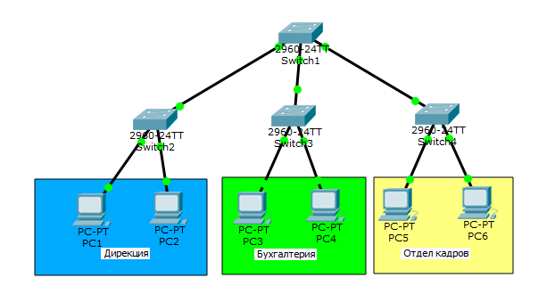
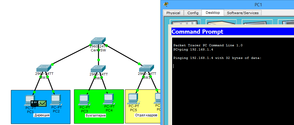
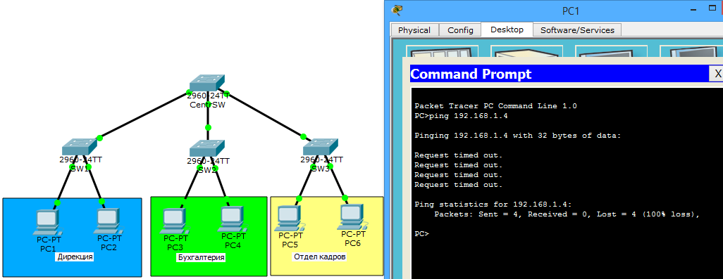
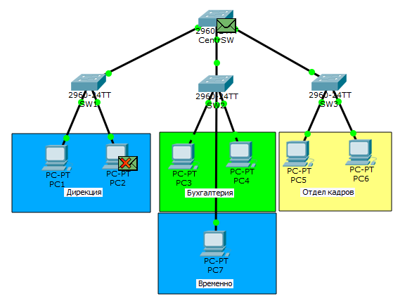
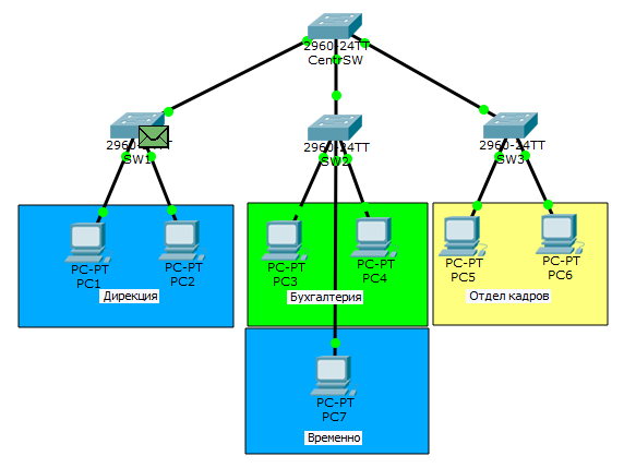
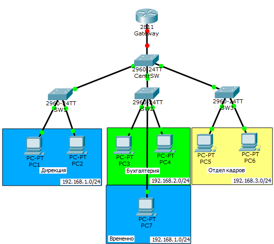
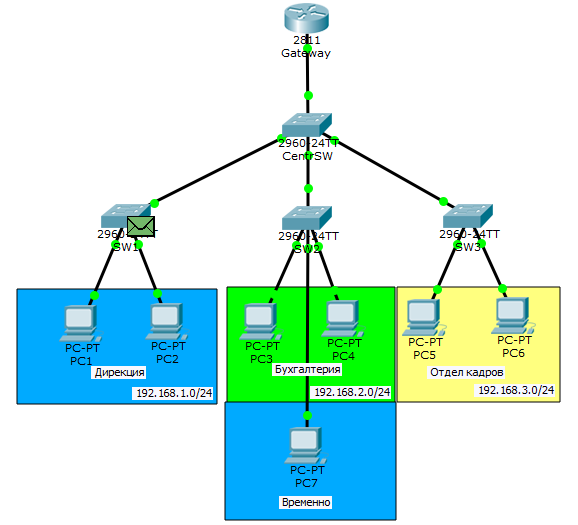
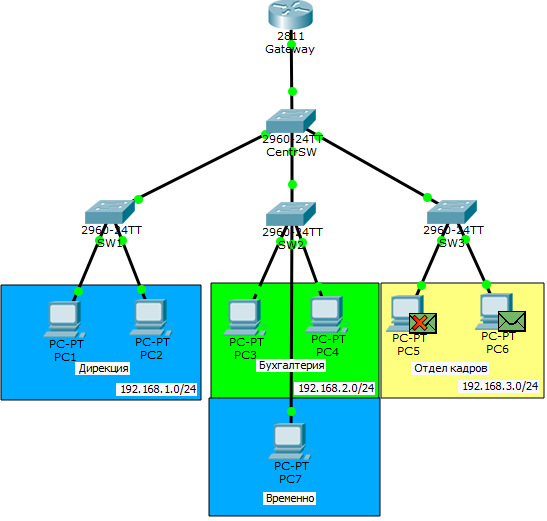
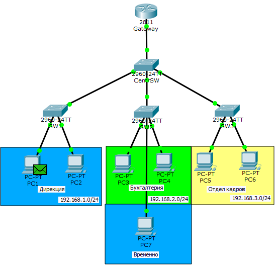
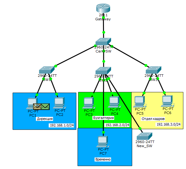
We have 3 departments: management, accounting, personnel department. Each department has its own switchboard and they are connected through the central upper one. And PC1 sends ping to PC2.

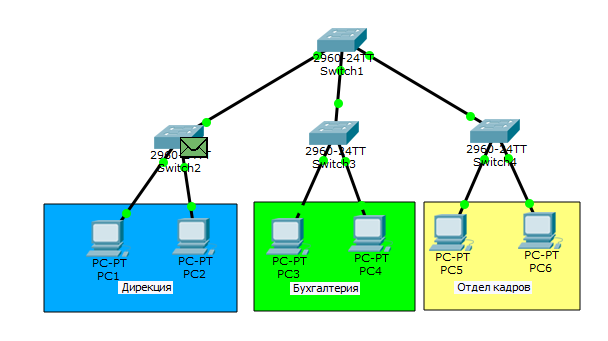
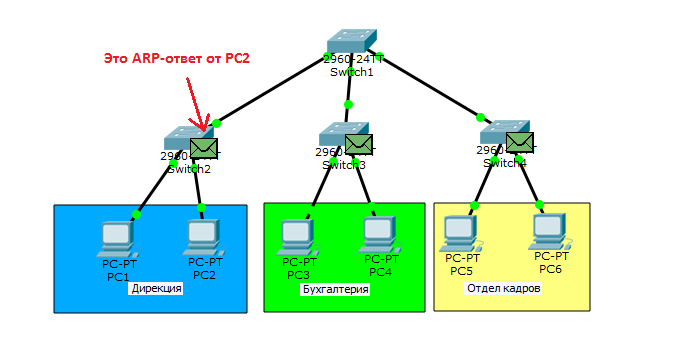
Who wants to see it in the form of animation, open the spoiler (ping from PC1 to PC5 is shown there).
Network operation in one broadcast domain
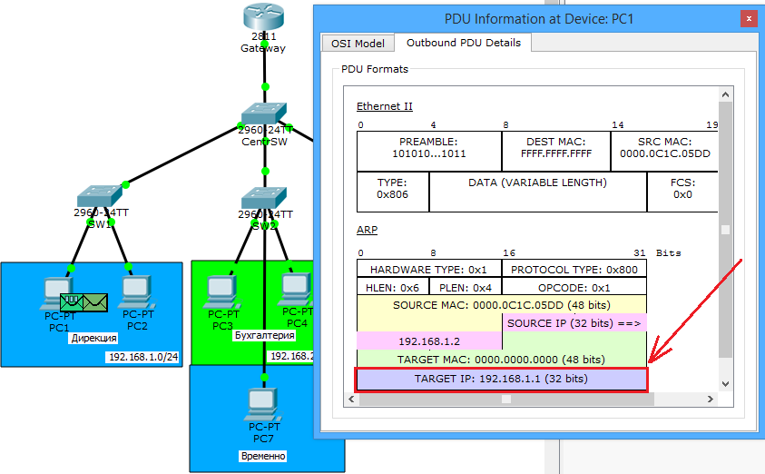
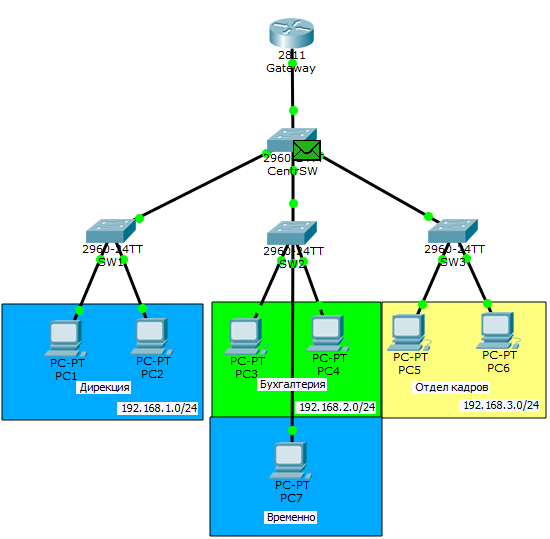
Beautiful yes? In previous articles, we have already talked more than once about the work of the ARP protocol, but this was last year, so I will briefly explain. Since PC1 does not know the MAC address (or data link layer address) of PC2, it sends an ARP exploration to let it know. It comes to the switch, from where it is relayed to all active ports, that is, to PC2 and to the central switch. From the central switch will fly to neighboring switches, and so on, until it reaches all. This is not a small traffic caused one ARP-message. He received all the members of the network. Large and unnecessary traffic is the first problem. The second problem is security. I think we noticed that the message reached even the accounting department, whose computers did not participate in it at all. Any intruder connecting to any of the switches will have access to the entire network. In principle, the network before and worked. The computers were in the same channel environment and were separated only with the help of routers. But time went and it was necessary to solve this problem on the channel level. Cisco, as a pioneer, came up with its own protocol, which tagged frames and determined the belonging to a specific channel environment. It was called ISL (Inter-Switch Link) . Everyone liked this idea and IEEE decided to develop a similar open standard. The standard is called 802.1q . He got a huge spread and Cisco decided to go on it too.
And that's how VLAN technology is based on the operation of the 802.1q protocol. Let's start talking about her.
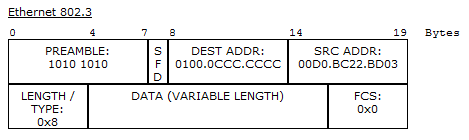
In part 3, I showed what an ethernet frame looks like. Look at it and refresh it. This is what an untagged frame looks like.

Now take a look at the tagged.
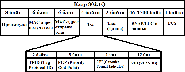
As you can see, the difference is that a certain tag appears. This is what is interesting to us. Digging deeper. It consists of 4 parts.
1) TPID (Tag Protocol ID) or Tagged Protocol Identifier - consists of 2 bytes and is always 0x8100 for a VLAN.
2) PCP (English Priority Code Point) or priority value - consists of 3 bits. Used to prioritize traffic. Steep and bearded system administrators know how to manage them correctly and operate them when there are different traffic on the network (voice, video, data, etc.)
3) CFI (English Canonical Format Indicator) or the canonical format indicator is a simple field consisting of one bit. If it is 0, then this is the standard MAC address format.
4) VID (English VLAN ID) or VLAN ID - consists of 12 bits and shows which VLAN is in the frame.
I want to focus attention on the fact that frame tagging is performed between network devices (switches, routers, etc.), and frames between the end node (computer, laptop) and network device are not tagged. Therefore, the network device port can be in 2 states: access or trunk .
- Access port or access port - a port located on a specific VLAN and sending untagged frames. Typically, this is a port looking at a user device.
- Trunk port or trunk port - a port that transmits tagged traffic. Typically, this port rises between network devices.
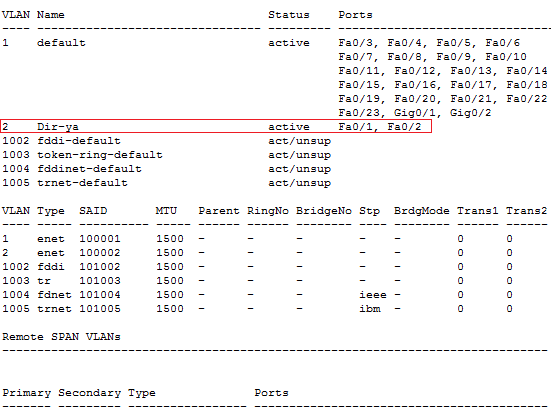
Now I will show it in practice. I open the same lab. I will not repeat the picture, but I will immediately open the switch and see what it has with the VLAN.
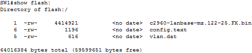
I type the show vlan command.

Lined up several tables. We are essentially only the very first important. Now I will show you how to read it.
1 column is the VLAN number. Number 1 is originally present here - this is the standard VLAN that is initially on each switch. It performs another function, about which I will write below. Reserved from 1002-1005 are also present. This is for other channel environments that are hardly ever used. You cannot delete them either.
Switch(config)#no vlan 1005 Default VLAN 1005 may not be deleted. When deleting, Cisco displays a message that this VLAN cannot be deleted. Therefore, we live and do not touch these 4 VLANs.
Column 2 is the VLAN name. When creating a VLAN, you can, at your discretion, come up with meaningful names for them to identify them later. There is already default, fddi-default, token-ring-default, fddinet-default, trnet-default.
3 column - status. It shows the state of the VLAN. At the moment, VLAN 1 or default is in the active state, and 4 of the following act / unsup (although active, but not supported).
4 column - ports. This shows which VLANs the ports belong to. Now, when we have not touched anything, they are in default.
Getting started configuring switches. A good tone rule will give intelligent switches names. What we do. I bring the team.
Switch(config)#hostname CentrSW CentrSW(config)# The rest are configured similarly, so I will show the updated topology diagram.
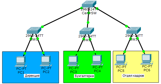
Begin setup with switch SW1. First, create a VLAN on the switch.
SW1(config)#vlan 2 - VLAN 2 (VLAN 1 , ). SW1(config-vlan)#name Dir-ya - VLAN . VLAN is created. Now go to the ports. The FastEthernet0 / 1 interface looks at PC1, and FastEthernet0 / 2 looks at PC2. As mentioned earlier, the frames between them should be transmitted untagged, so we translate them into the Access state.
SW1(config)#interface fastEthernet 0/1 - 1- . SW1(config-if)#switchport mode access - access. SW1(config-if)#switchport access vlan 2 - 2- VLAN. SW1(config)#interface fastEthernet 0/2 - 2- . SW1(config-if)#switchport mode access - access. SW1(config-if)#switchport access vlan 2 - 2- VLAN. Since both ports are assigned to the same VLAN, they could still be configured as a group.
SW1(config)#interface range fastEthernet 0/1-2 - . SW1(config-if-range)#switchport mode access SW1(config-if-range)#switchport access vlan 2 Configure access ports. Now configure the trunk between SW1 and CentrSW.
SW1(config)#interface fastEthernet 0/24 - 24- . SW1(config-if)#switchport mode trunk - trunk. %LINEPROTO-5-UPDOWN: Line protocol on Interface FastEthernet0/24, changed state to down %LINEPROTO-5-UPDOWN: Line protocol on Interface FastEthernet0/24, changed state to up We immediately see that the port has migrated. In principle, this is enough for work. But from a security point of view, only those VLANs that are really needed are allowed for transmission. Let's get started
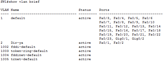
SW1(config-if)#switchport trunk allowed vlan 2 - 2- VLAN. Without this command, all available VLANs will be transmitted. Let's see how the table has changed with the show vlan command.
A second VLAN appeared with the name Dir-ya and we see ports fa0 / 1 and fa0 / 2 that belong to it.
To display only the top table, you can use the show vlan brief command.
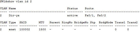
You can still shorten the output, if you specify a specific VLAN ID.
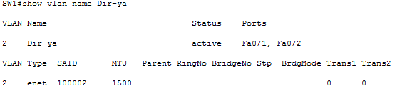
Or his name.
All VLAN information is stored in flash memory in the vlan.dat file.
As you noticed, in none of the commands, there is no information about the trunk. It can be viewed by another show interfaces trunk command.

There is information about both the trunk ports and which VLANs they transmit. There is also a Native vlan column. This is exactly the traffic that should not be tagged. If a non-tagged frame arrives at the switch, it is automatically assigned to Native Vlan (by default, in our case, this is VLAN 1). Native VLAN is possible, and many say that you need to change for security purposes. To do this, in the configuration mode of the trunk port, you need to apply the command - switchport trunk native vlan X , where X is the number of the assigned VLAN. In this topology, we will not change, but knowing how to do it is useful.
It remains to configure the rest of the device.
CentrSW:
The central switch is the link, which means that it should be aware of all VLANs. Therefore, we first create them, and then translate all interfaces into trunk mode.
CentrSW(config)#vlan 2 CentrSW(config-vlan)# name Dir-ya CentrSW(config)#vlan 3 CentrSW(config-vlan)# name buhgalter CentrSW(config)#vlan 4 CentrSW(config-vlan)# name otdel-kadrov CentrSW(config)#interface range fastEthernet 0/1-3 CentrSW(config-if-range)#switchport mode trunk Do not forget to save the config. The copy running-config startup-config command .
SW2:
SW2(config)#vlan 3 SW2(config-vlan)#name buhgalter SW2(config)#interface range fastEthernet 0/1-2 SW2(config-if-range)#switchport mode access SW2(config-if-range)#switchport access vlan 3 SW2(config)#interface fastEthernet 0/24 SW2(config-if)#switchport mode trunk SW2(config-if)#switchport trunk allowed vlan 3 SW3:
SW3(config)#vlan 4 SW3(config-vlan)#name otdel kadrov SW3(config)#interface range fastEthernet 0/1-2 SW3(config-if-range)#switchport mode access SW3(config-if-range)#switchport access vlan 4 SW3(config)#interface fastEthernet 0/24 SW3(config-if)#switchport mode trunk SW3(config-if)#switchport trunk allowed vlan 4 Notice that we raised and configured the VLAN, but the addressing of the nodes was left the same. That is, virtually all nodes in the same subnet, but separated by VLAN-s. So you can not do. Each VLAN should be allocated a separate subnet. I did this solely for educational purposes. If each department were sitting on its own subnet, then they would have been limited a priori, since the switch does not know how to route traffic from one subnet to another (plus this is already a restriction at the network level). And we need to limit the departments at the link level.
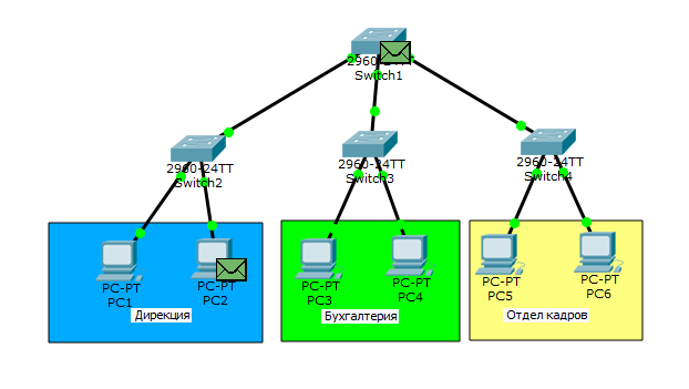
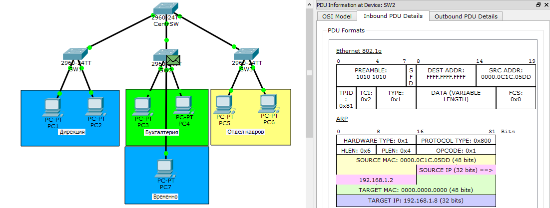
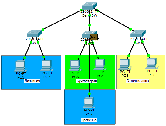
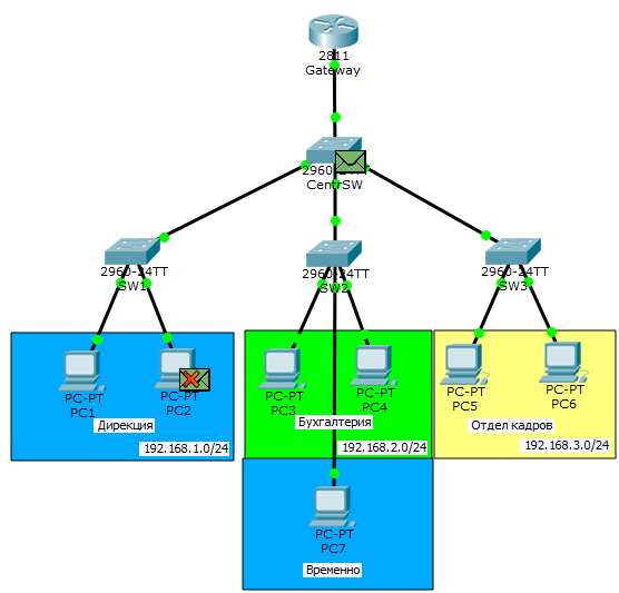
Ping from PC1 to PC3 again.
It goes into the course of ARP, which we need now. Open it.

So far, nothing new. ARP is encapsulated in ethernet.
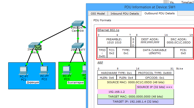
The frame arrives at the switch and is tagged. Now there is not a normal ethernet, but 802.1q. Added fields, about which I wrote earlier. This is a TPID that is 8100 and indicates that this is 802.1q. And TCI , which combines 3 PCP, CFI and VID fields. The number in this field is the VLAN number. Moving on.

After the tag, it sends a frame to PC2 (since it is in the same VLAN) and to the central switch via the trunk port.
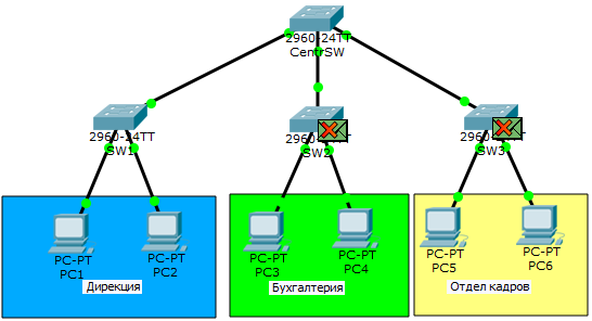
Since it was not strictly prescribed which types of VLANs to pass on which ports, it will send to both switches. And here the switches, having seen the VLAN number, understand that they do not have devices with such a VLAN, and boldly discard it.
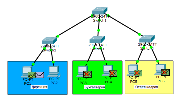
PC1 is waiting for a response that never comes. You can look under the spoiler in the form of animation.
Animation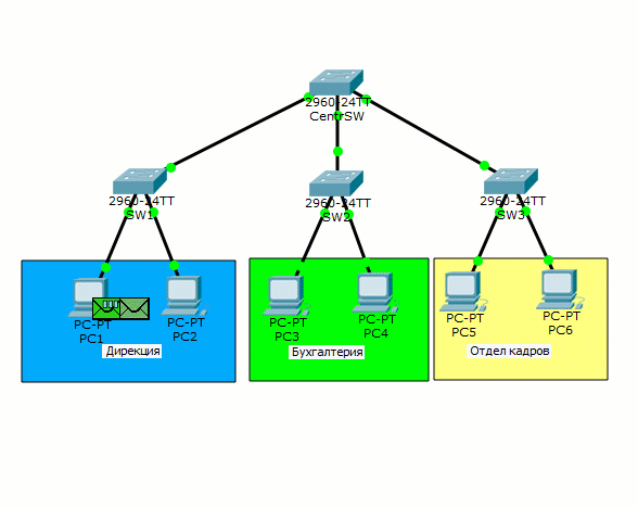
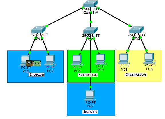
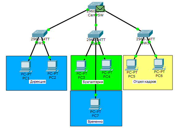
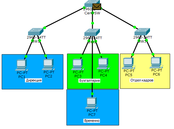
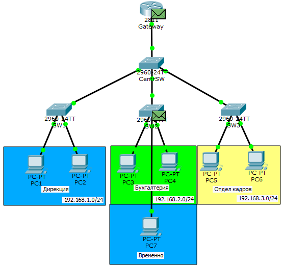
Now the following situation. The directorate hires another person, but there is no room in the directorate’s office and they are temporarily asked to place a person in the accounting department. We solve this problem.

We connected a computer to the FastEthernet 0/3 port of the switch and assigned the IP address 192.168.1.8/24.
Now I will configure the SW2 switch. Since the computer must be in the 2nd VLAN, which the switch does not know about, we will create it on the switch.
SW2(config)#vlan 2 SW2(config-vlan)#name Dir-ya Next, configure the FastEthernet 0/3 port, which looks at PC7.
SW2(config)#interface fastEthernet 0/3 SW2(config-if)#switchport mode access SW2(config-if)#switchport access vlan 2 And the last - to configure the trunk port.
SW2(config)#interface fastEthernet 0/24 SW2(config-if)#switchport trunk allowed vlan add 2 - . "add". , VLAN . VLAN, . So that the frames go beautifully, I will correct the central switch CentrSW.
CentrSW(config)#interface fastEthernet 0/1 CentrSW(config-if)#switchport trunk allowed vlan 2 CentrSW(config)#interface fastEthernet 0/2 CentrSW(config-if)#switchport trunk allowed vlan 2,3 CentrSW(config)#interface fastEthernet 0/3 CentrSW(config-if)#switchport trunk allowed vlan 4 Checkout time. Ping from PC1 to PC7.
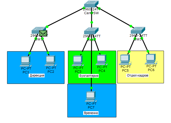
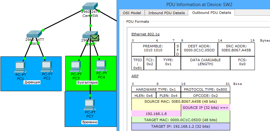
So far, the whole journey is similar to the previous one. But from now on (from the image below), the central switch will make another decision. It receives a frame and sees that it is patched by the 2nd VLAN. So you need to send it only where it is allowed, that is, to port fa0 / 2.
And here he comes to SW2. We open and see that it is still tagged. But the next node is a computer and the tag must be removed. Click on "Outbound PDU Details" to see how the frame will fly out of the switch.

And really. The switch will send the frame in a “pure” form, that is, without tags.

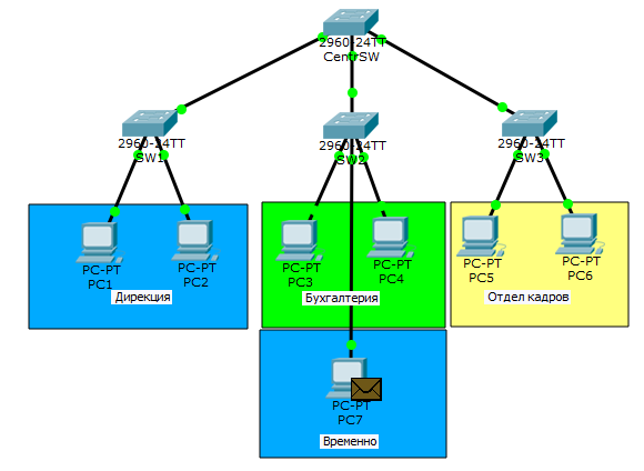
ARP reaches PC7. Open it and make sure that the frame is not tagged PC7 recognized himself and sends the answer.
We open the frame on the switch and see that it will go tagged to send. The next frame will travel the same way that it came.

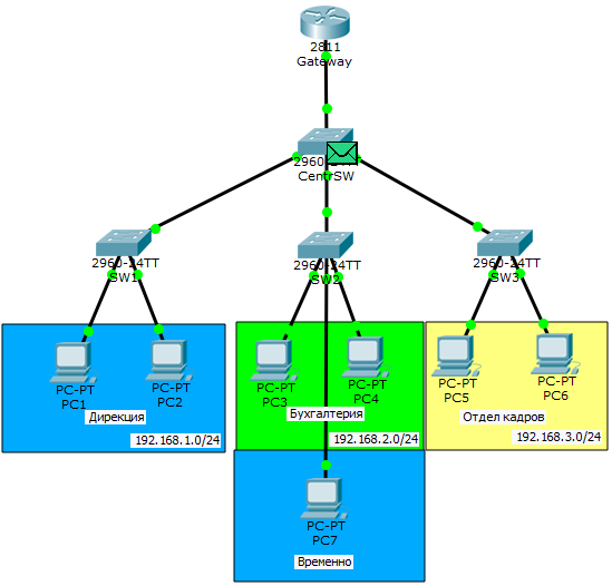
ARP comes to PC1, as indicated by a check mark on the envelope. Now he knows the MAC address and he launches ICMP.

Open the package on the switch and see the same picture. At the data link layer, the frame is tagged by the switch. So it will be with every message.
We see that the package successfully reaches PC7. I will not show the way back, since it is similar. If anyone is interested, you can see all the way on the animation under the spoiler below. And if you want to pick this topology yourself, I attach a link to the lab.
VLAN operation logic
That's basically the most popular use of VLANs. Regardless of physical location, you can logically combine nodes into groups, thereby isolating them from others. It is very convenient when employees physically work in different places, but must be combined. And of course, from the point of view of security, VLANs are not interchangeable. The main thing is that a limited circle of people have access to network devices, but this is a separate topic.
Have achieved restrictions at the link level. Traffic no longer walks anywhere, but goes strictly according to its intended purpose. But now the question arises that the departments need to communicate with each other. And since they are in different channel environments, routing comes into play. But before we start, we will put the topology in order. The very first thing to which we add a hand is the addressing of nodes. I repeat that each department must be on its own subnet. Total we get:
- Directorate - 192.168.1.0/24
- Accounting - 192.168.2.0/24
- Human Resources Department - 192.168.3.0/24
Once the subnets are defined, we immediately address the nodes.
- PC1:
IP: 192.168.1.2
Mask: 255.255.255.0 or / 24
Gateway: 192.168.1.1 - PC2:
IP: 192.168.1.3
Mask: 255.255.255.0 or / 24
Gateway: 192.168.1.1 - PC3:
IP: 192.168.2.2
Mask: 255.255.255.0 or / 24
Gateway: 192.168.2.1 - PC4:
IP: 192.168.2.3
Mask: 255.255.255.0 or / 24
Gateway: 192.168.2.1 - PC5:
IP: 192.168.3.2
Mask: 255.255.255.0 or / 24
Gateway: 192.168.3.1 - PC6:
IP: 192.168.3.3
Mask: 255.255.255.0 or / 24
Gateway: 192.168.3.1 - PC7:
IP: 192.168.1.4
Mask: 255.255.255.0 or / 24
Gateway: 192.168.1.1
Now about the changes in the topology. We see that the router has been added. It will just transfer traffic from one VLAN to another (in other words, route). Initially, there is no connection between it and the switch, since the interfaces are turned off.
At nodes such parameter as the gateway address was added. They use this address when they need to send a message to a node located on another subnet. Accordingly, each subnet has its own gateway.
It remains to configure the router, and I open its CLI. By tradition, I will give a meaningful name.
Router(config)#hostname Gateway Gateway(config)# Next, go to the interface settings.
Gateway(config)#interface fastEthernet 0/0 - . Gateway(config-if)#no shutdown - . %LINK-5-CHANGED: Interface FastEthernet0/0, changed state to up %LINEPROTO-5-UPDOWN: Line protocol on Interface FastEthernet0/0, changed state to up Now attention! We enabled the interface, but did not hang an IP address on it. The fact is that from the physical interface (fastethernet 0/0) you only need a link or channel. The role of the gateways will be performed by virtual interfaces or subinterfaces. Currently there are 3 types of VLAN. Hence, the subinterfaces will be 3. We proceed to configure.
Gateway(config)#interface fastEthernet 0/0.2 Gateway(config-if)#encapsulation dot1Q 2 Gateway(config-if)#ip address 192.168.1.1 255.255.255.0 Gateway(config)#interface fastEthernet 0/0.3 Gateway(config-if)#encapsulation dot1Q 3 Gateway(config-if)#ip address 192.168.2.1 255.255.255.0 Gateway(config)#interface fastEthernet 0/0.4 Gateway(config-if)#encapsulation dot1Q 4 Gateway(config-if)#ip address 192.168.3.1 255.255.255.0 The router is configured. Go to the central switch and configure the trunk port on it so that it passes tagged frames to the router.
CentrSW(config)#interface fastEthernet 0/24 CentrSW(config-if)#switchport mode trunk CentrSW(config-if)#switchport trunk allowed vlan 2,3,4 The configuration is complete and proceed to practice. I send ping from PC1 to PC6 (that is, to 192.168.3.3).
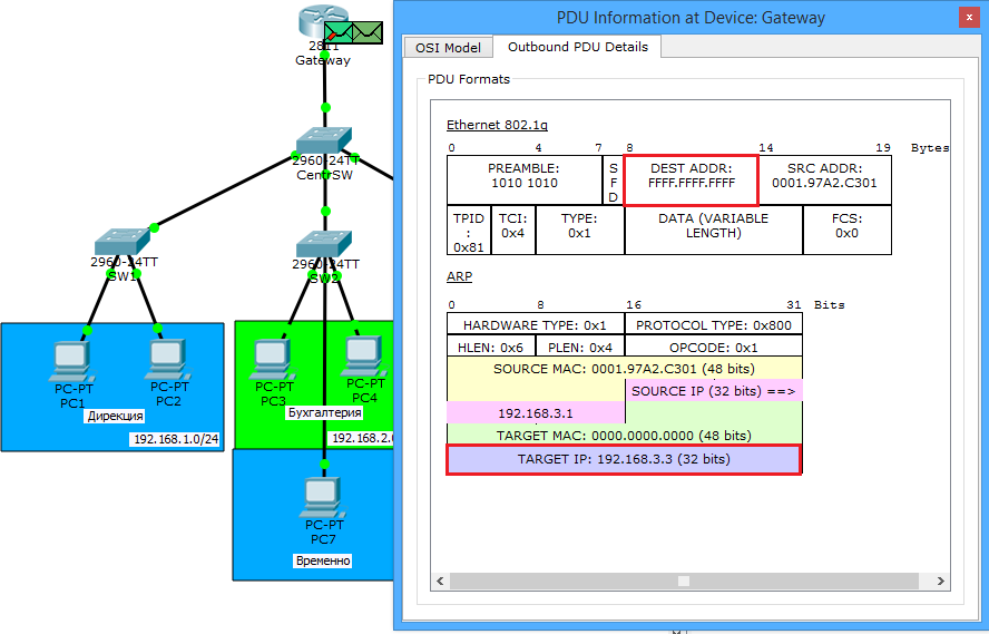
PC1 has no idea who PC6 is or 192.168.3.3, but knows that they are on different subnets (as he understands described in the previous article). Therefore, he will send a message through the main gateway whose address is specified in its settings. And although PC1 knows the IP address of the main gateway, there is not enough MAC address for complete happiness. And he launches ARP.

Note. As soon as the frame arrives at CentrSW, the switch does not send it to anyone. It sends only to those ports where 2nd VLAN skipping is allowed. That is, on the router and on SW2 (there is a user sitting in the 2nd VLAN).

The router recognizes itself and sends a response (indicated by the arrow). And look at the bottom frame. When SW2 received ARP from the central switch, it likewise did not send it to all computers, but sent only PC7, which sits in the 2nd VLAN. But PC7 discards it, as it is not for it. We look further.

ARP reached PC1. Now he knows everything and can send ICMP. Once again I will pay attention to the fact that as the destination MAC address (link layer), there will be the address of the router, and as the destination IP address (network level), the address is PC6.

ICMP reaches the router. He looks into his table and realizes that he does not know anyone under the address 192.168.3.3. ICMP arrives discarding and starts scouting ARP.


PC6 recognizes itself and sends the answer.

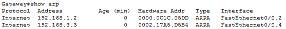
The answer reaches the router and it adds an entry in its table. You can view the ARP table with the show arp command.
Moving on. PC1 is unhappy that no one answers it and sends the next ICMP message.


This time ICMP comes without problems. Back he will follow the same route. I will only show the end result.
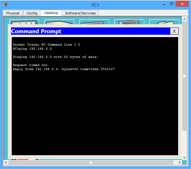
The first packet was lost (as a result of ARP), and the second one came without problems.
Who is interesting to see in the animation, welcome under the spoiler.
InterVLAN Routing
So. We have ensured that if the nodes are on the same subnet and one VLAN, then they will go directly through the switches. In the case when it is necessary to transfer a message to another subnet and VLAN, then they will transmit via the Gateway router, which performs the “interwave” routing. This topology is called "router on a stick" or "router on a stick" . As you understand it is very convenient. We created 3 virtual interfaces and drove different tagged frames on one wire. Without using subinterfaces and VLANs, we would have to use a separate physical interface for each subnet, which is not at all profitable.
By the way, this question is very well analyzed in this video (the video is about 3 hours, so the link is linked to exactly that point in time). If after reading and watching the video I want to finish everything with my own hands, I attach a link to download.
We dealt with VLANs and proceed to one of the protocols working with it.
DTP (English Dynamic Trunking Protocol) or in Russian Dynamic Trunking Protocol is a proprietary protocol of Cisco, which serves to implement the trunk mode between switches. Although depending on the state, they may be consistent in access mode.
There are 4 modes in DTP: Dynamic auto, Dynamic desirable, Trunk, Access. Consider how they agree.
| Modes | Dynamic auto | Dynamic desirable | Trunk | Access |
|---|---|---|---|---|
| Dynamic auto | Access | Trunk | Trunk | Access |
| Dynamic desirable | Trunk | Trunk | Trunk | Access |
| Trunk | Trunk | Trunk | Trunk | No connection |
| Access | Access | Access | No connection | Access |
That is, the left column is the 1st device, and the top line is the 2nd device. By default, switches are in dynamic auto mode. If you look at the mapping table, the two switches in the “dynamic auto” mode are matched to the “access” mode. Let's check it out. I create a new lab and add 2 switches.
Connect them until I will. I need to make sure that both switches are in dynamic auto mode. I will check with the show interfaces switchport command.
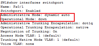
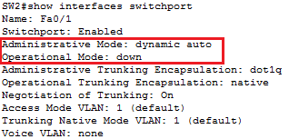
The result of this command is very large, so I cut it off and selected points of interest. Let's start with Administrative Mode . This line shows in which of the 4 modes this port is working on the switch. Make sure that ports on both switches are in Dynamic auto mode. And the line Operational Mode shows in which mode of operation they have coordinated the work. We have not connected them yet, so they are in the "down" state.
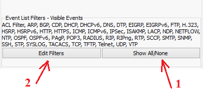
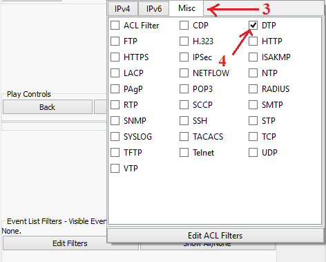
Immediately give you good advice. When testing any protocol, use filters. Turn off the display of all unnecessary protocols.
I put CPT in simulation mode and filter out all protocols except DTP.
I think everything is clear here. I connect switches with cable and, when raising links, one of the switches generates a DTP message.
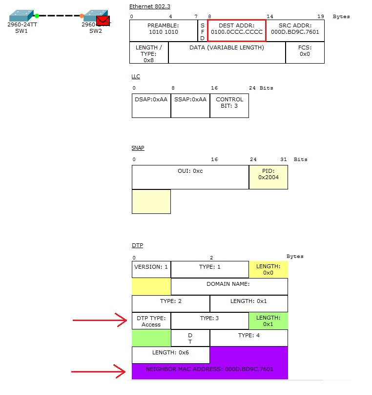
I open it and see that it is a DTP encapsulated in an Ethernet frame. He sends it to the multicast address "0100.0ccc.c.cccc", which relates to the DTP, VTP, CDP protocols.
And pay attention to the 2 fields in the DTP header.
1) DTP Type - here the sending inserts an offer. That is, in what mode he wants to agree. In our case, he suggests matching “access”.
2) Neighbor MAC-address - in this field, it writes the MAC address of its port.
He sends and waits for a reaction from a neighbor.
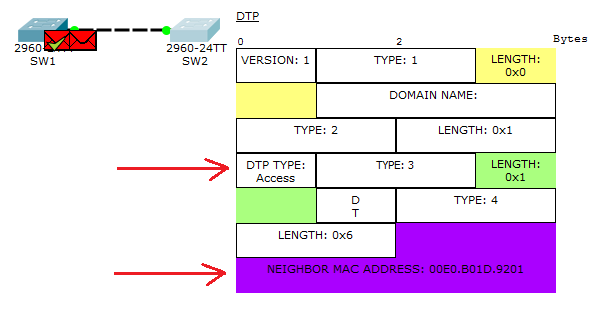
It reaches the SW1 message and it generates a reply. Where also the “access” mode is negotiated, inserts its MAC address and sends it to SW2.
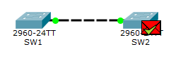
Successfully reaches DTP. In theory, they should have been coordinated in the “access” mode. I'll check.

As expected, they agreed to the “access” mode.
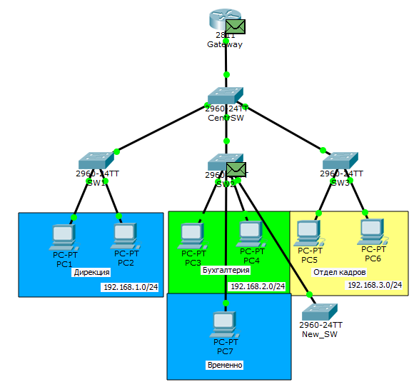
Someone says that the technology is convenient and uses it. But I highly recommend not using this protocol in my network. I recommend this not only me, and now I will explain why. The point is that this protocol opens a big security hole. I will open the lab in which the work “Router on a stick” was sorted out and add one more switch there.
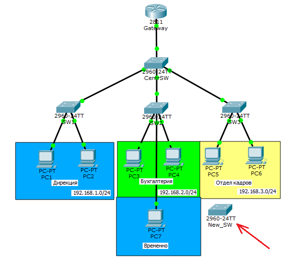
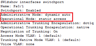
Now I’ll go into the settings of the new switch and strictly register the work in the trunk mode on the port.
New_SW(config)#interface fastEthernet 0/1 New_SW(config-if)#switchport mode trunk Connect them and see how they agreed.
That's right. The “dynamic auto” and “trunk” modes are matched to trunk mode. Now we are waiting for someone to start being active. Suppose PC1 decided to send someone a message. Generates ARP and releases to the network.
Let's skip his way to the moment when he gets on SW2.
And the most interesting.

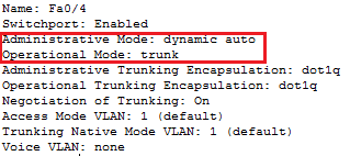
He sends it to the newly connected switch. I explain what happened. As soon as we agreed with him on the trunk, he starts sending him all the incoming frames. Although the diagram shows that the switch discards frames, it does not mean anything. You can connect any sniffer device to the switch or instead of the switch and calmly watch what is happening in the network. It seems he intercepted a harmless ARP. But if you take a deeper look, you can see that the MAC address “0000.0C1C.05DD” and the IP address “192.168.1.2” are already known. That is, PC1, without thinking, betrayed himself. Now the attacker knows about such a computer. In addition, he knows that he is sitting in the 2nd VLAN. Then he can mess things up. The most trivial thing is to change your MAC address, IP address, agree quickly in Access, and impersonate PC1. But the most interesting. After all, you can not immediately understand. Usually, when we register the port operation mode, it is immediately displayed in the configuration. I enter show running-config .
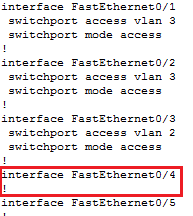
But here the port settings are empty. I enter show interfaces switchport and scroll to fa0 / 4.
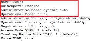
And here we see that the trunk is agreed. Not always show running-config gives comprehensive information.Therefore, remember and other teams.
I think it is clear why you can not trust this protocol. He seems to make life easier, but at the same time can create a huge problem. So rely on the manual method. When setting up, immediately identify yourself which ports will work in trunk mode, and which ones in access. And most importantly - always disable the negotiation. So that the switches do not try to agree with anyone. This is done with the command “switchport nonegotiate”.
Moving on to the next protocol.
VTP (English VLAN Trunking Protocol) is a proprietary protocol from Cisco, which is used to exchange information about VLANs.
Imagine the situation that you have 40 switches and 70 VLANs. For good, you need to manually create them on each switch and register on which trunk ports to allow transfer. The case is dreary and long. Therefore, the VTP can take on this task. You create a VLAN on one switch, and all the others are synchronized with its base. Take a look at the following topology.

There are 4 switches here. One of them is a VTP server, and the other 3 are clients. Those VLANs that will be created on the server are automatically synchronized on the clients. I will explain how VTP works and what it can do.
So.VTP can create, modify and delete VLANs. Each such action leads to the fact that the revision number increases (each action increases the number by +1). After he sends the ads, where the number of the revision. Clients who receive this announcement compare their revision number with the number that came. And if the incoming number is higher, they synchronize their base with it. Otherwise, the ad is ignored.
But that is not all.VTP has roles. By default, all switches work as a server. I'll tell you about them.
- VTP Server . Able all. That is, creates, modifies, deletes VLANs. If it receives an ad in which the revision is older than it, then it is synchronized. Constantly sends announcements and relays from neighbors.
- VTP Client — . , VLAN . VLAN . VLAN-.
- VTP Transparent — . , VLAN . . , , . , , 0.
This is all about VTP version 2. Another role has been added to VTP 3rd version - VTP Off . It does not transmit any ads. The rest of the work is similar to the mode Transparent .
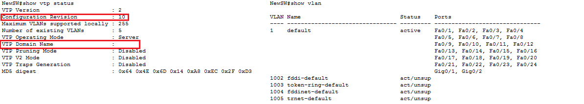
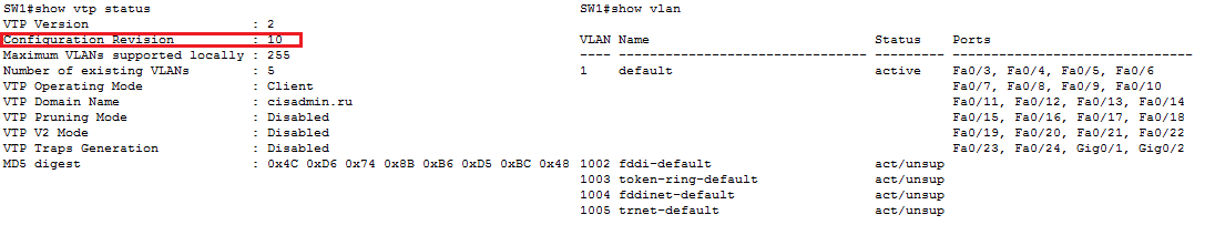
We read the theory and proceed to practice. Verify that the central switch is in Server mode. Enter the show vtp status command .
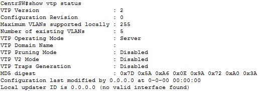
We see that the VTP Operating Mode: Server. You may also notice that the VTP version is 2nd. Unfortunately, 3rd version is not supported in CPT. Revision version zero.
Now configure the lower switches.
SW1(config)#vtp mode client Setting device to VTP CLIENT mode. We see a message that the device has switched to client mode. The rest is configured exactly the same.
For devices to be able to exchange ads, they must be in the same domain. And there is a feature. If the device (in Server or Client mode) does not belong to any domain, then upon the first advertisement received, it will switch to the declared domain. If the client is in some domain, then there will be no ads from other domains. Open SW1 and make sure that it is not in any domain.

Make sure it's empty.
Now go to the central switch and translate it into a domain.
CentrSW(config)#vtp domain cisadmin.ru Changing VTP domain name from NULL to cisadmin.ru We see the message that it was transferred to the cisadmin.ru domain.
Check the status.

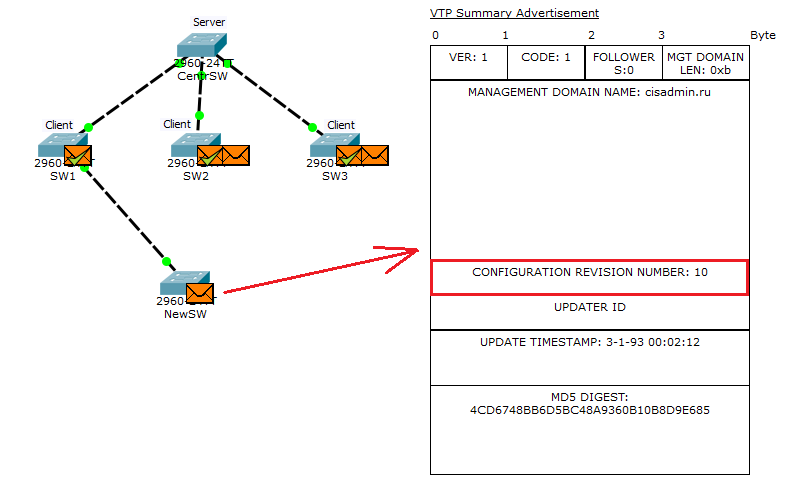
And really. The domain name has changed. Please note that the revision number is still zero. It will change as soon as we create a VLAN on it. But before creating, you need to put the simulator into simulation mode in order to see how it will generate ads. We create the 20th VLAN and see the following image.

As soon as the VLAN is created and the revision number has increased, the server generates announcements. He has two of them. First, open the one to the left. This announcement is called “Summary Advertisement” or in Russian “consolidated announcement”. This ad is generated by the switch every 5 minutes, where it talks about the domain name and the current revision. See how it looks.
In the Ethernet frame, note the Destination MAC address. It is the same as above when DTP was generated. That is, in our case, only those who are running VTP will respond to it. Now look at the next field.

Here is all the information. Walk through the most important fields.
- Management Domain Name - the name of the domain itself (in this case, cisadmin.ru).
- Updater Identity - identifier of the person who updates. Here, as a rule, the IP address is recorded. But since the address was not assigned to the switch, the field is empty
- Update Timestamp - update time. Time on the switch has not changed, so there is a factory.
- MD5 Digest - MD5 hash. It is used to verify credentials. That is, if the password is on the VTP. We did not change the password, so the default hash.
Now look at the next generated message (the one on the right). It is called a “Subset Advertisement” or “Detailed Ad.” This is such detailed information about each VLAN transmitted.

I think it’s understandable here. Separate header for each VLAN type. The list is so long that it does not fit on the screen. But they are exactly the same, except for the names. I will not bother with my head, which means every code. Yes, and in the CPT, they are more convention here.
We look what happens next.

Receive clients ads. They see that the revision number is higher than theirs and synchronize the base. And they send a message to the server that the base of VLANs has changed.

How VTP works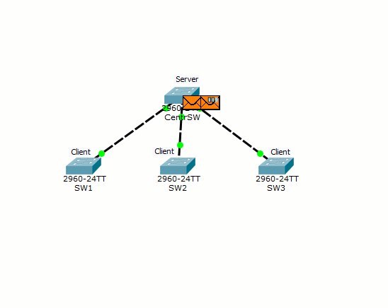
This is how VTP works. But he has very big minuses. And these cons in terms of security. I will explain on the example of the same lab. We have a central switch, on which VLANs are created, and then, via a multicast, it synchronizes them with all the switches. In our case, he talks about VLAN 20. I suggest once again to look at its configuration.

And here we are adding a new switch to the network. It does not have new VLANs other than the standard ones and it does not belong to any VTP domain, but the revision number is tied up.
And before plugging it into the network, we transfer the port to trunk mode.

Now I switch CPT to “Simulation Mode” and filter everything except VTP. Connect and watch what happens.
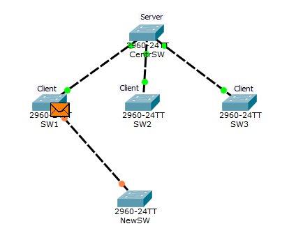

After some time, a VTP message comes to NewSW, from where it finds out that the network has a VTP domain "cisadmin.ru". Since he was not previously in another domain, he automatically enters it. Check it out.

Now it is in the same domain, but with the revision number above. He forms a VTP message where he talks about it.
SW1 will fall under the distribution first.

Note that 2 VTP messages arrive at once from SW1 (from NewSW and from CentrSW). In a message from NewSW, he sees that the revision number is higher than his and synchronizes his base. But the message from CentrSW is already outdated for him, and he discards it. Check what has changed on SW1.
The revision number has been updated and, most interestingly, the VLAN database. Now it is empty. We look further.


Note.The server receives a VTP message, where the revision number is higher than that of it. He understands that the network has changed and it is necessary to adapt to it. Check the configuration.

The configuration of the central server has changed and now it will broadcast it.
Now imagine that we have not one VLAN, but hundreds. In such a simple way you can put the network. Of course, the domain can be password protected and the attacker will be harder to cause harm. And imagine the situation that your switch broke and you urgently need to replace it. You or your colleague run to the warehouse behind the old switchboard and forget to check the revision number. It is higher than the rest. What happens next, you have already seen. Therefore, I recommend not using this protocol. Especially in large corporate networks. If you are using 3rd party VTP, feel free to switch the switches to “Off” mode. If the 2nd version is used, then transfer to the “Transparent” mode.
Who is interested to see it in the form of animation, open the spoiler.
Connecting a switch with a higher revision
For those who want to work with this lab, I attach a link .
Well, the article about the VLAN came to an end. If you have any questions, feel free to ask. Thanks for reading.
Source: https://habr.com/ru/post/319080/
All Articles