Theoretical Foundations of VMware Virtual SAN 6.5
In this article, I tried to reveal the purpose of the VMware Virtual SAN, its principles of operation, the requirements, capabilities and limitations of this system, the main recommendations for its design.
VMware Virtual SAN (hereinafter referred to as vSAN) is a distributed software storage system (SDS) for organizing a hyper-convergent infrastructure (HCI) based on vSphere. vSAN is built into the ESXi hypervisor and does not require the deployment of additional services and service VMs. vSAN allows you to combine local host media into a single storage pool, providing a given level of fault tolerance and providing its space for all hosts and cluster VMs. Thus, we get the centralized storage necessary to reveal all the possibilities of virtualization (vSphere technology), without the need to implement and maintain a dedicated (traditional) storage system.
vSAN is started at the vSphere cluster level, it is enough to start the corresponding service in cluster management and provide it with local storage media of the cluster hosts - in manual or automatic mode. vSAN is built into vSphere and tightly attached to it, as a standalone SDS product that can work outside of the VMware infrastructure, cannot exist.
Analogues and vSAN competitors are: Nutanix DSF (Nutanix distributed storage), Dell EMC ScaleIO, Datacore Hyper-converged Virtual SAN, HPE StoreVirtual. All these solutions are compatible not only with VMware vSphere, but also with MS Hyper-V (some with KVM), they require installation and launch of a service VM on each HCI host required for SDS operation; they are not embedded in the hypervisor.
')
An important property of any HCI, incl. VMware vSphere + vSAN, is the horizontal scalability and modularity of the architecture. HCI is built and expanded on the basis of identical server blocks (hosts or nodes), combining computing resources, storage resources (local media) and network interfaces. This may be a commodity-equipment (x86 servers, including brand), supplied separately, or ready-made eplaences (for example, Nutanix, vxRail, Simplivity). Comprehensive software (for example, vSphere + vSAN + VMware__working tools) allows you to create a software-defined data center (SDDS) based on these blocks, including a virtualization environment, SDN (software-defined network), SDS, centralized management and automation / orchestra. Of course, we must not forget about the need for dedicated physical network equipment (switches), without which interaction between HCI hosts is impossible. At the same time for the organization of the network, it is advisable to use leaf-spine architecture, optimal for the data center.
The vSAN rises at the cluster level of ESXi hosts managed by vCenter and provides distributed centralized storage to the hosts of the cluster. The vSAN cluster can be implemented in 2 versions:
• Hybrid - flash drives are used as cache (cache layer), HDD provide the main storage capacity (capacity layer).
• All-flash flash drives are used at both levels: cache and capacity.
Extending a vSAN cluster is possible by adding media to existing hosts or by installing new hosts in the cluster. It should be borne in mind that the cluster should remain balanced, which means that, ideally, the composition of the media in the hosts (and the hosts themselves) should be identical. It is admissible, but not recommended, to include in the cluster hosts without media participating in the vSAN capacity; they can also place their VMs on the common storage of the vSAN cluster.
Comparing vSAN with traditional external storage systems, it should be noted that:
• vSAN does not require the organization of external storage and a dedicated storage network;
• vSAN does not require cutting LUNs and file balls, presenting them to hosts and the associated network interaction settings; after activation, vSAN immediately becomes available to all hosts in the cluster;
• vSAN data transmission is carried out according to its own proprietary protocol; standard SAN / NAS protocols (FC, iSCSI, NFS) are not needed for the organization and operation of vSAN;
• vSAN administration is performed only from the vSphere console; separate administration tools or special plug-ins for vSphere are not needed;
• do not need a dedicated storage administrator; vSAN configuration and maintenance is done by the vSphere administrator.
On each host of the vSAN cluster there must be at least one cache and one storage medium (capacity or data disk). These media within each host are combined into one or more disk groups. Each disk group includes only one cache medium and one or more data carriers for permanent storage.
The media given to the vSAN and added to the disk group is fully utilized, it cannot be used for other tasks or in several disk groups. This applies to both the cache carrier and the capacity of the disks.
vSAN only supports local storage media or drives connected via DAS. Inclusion of storage connected via SAN / NAS to the vSAN storage pool is not supported.
vSAN is an object storage, the data in it is stored in the form of “flexible” (flexible) containers called objects. The object stores within itself data or meta-data distributed across the cluster. The following are the main types of vSAN objects (created separately for each VM):
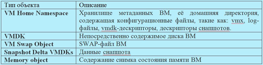
Thus, the data of each VM is stored on the vSAN as a set of objects listed above. In turn, each object includes a set of components distributed across the cluster depending on the selected storage policy and the amount of data.
Storage management on vSAN is implemented using the SPBM (Storage Policy Based Management) mechanism, which affects all vSphere repositories starting with version 6. The storage policy sets the number of allowable failures (Number of failures to tolerate), the fault tolerance method (replication or erasure coding) and the number of stripes for the object (Number of disk stripes per object). The number of stripes specified by the policy determines the number of data carriers (capacity) over which the object will be spread.
Binding a policy to a specific VM or its disk determines the number of object components and their distribution across the cluster.
vSAN allows changing storage policy for hot-on objects without stopping VM operation. At the same time in the background the processes of reconfiguration of objects are launched.
When objects are distributed across a cluster, vSAN controls that components related to different object replicas and witness components are distributed to different nodes or domains of failure (server rack, basket or platform).
A witness is a service component that does not contain useful data (only metadata), its size is 2-4MB. It performs the role of a tiebreaker in determining the living components of an object in case of failures.
The quorum calculation mechanism in vSAN works as follows. Each component of the object receives a certain number of votes (votes) - 1 or more. A quorum is reached and the object is considered “alive” if its full replica is available and more than half of its votes.
Such a quorum calculation mechanism allows you to distribute the components of an object across a cluster in such a way that in some cases you can do without creating a witness. For example, when using RAID-5/6 or striping on RAID-1.
After enabling the vSAN service in the vSphere cluster, the repository of the same name (datastore) appears, it can only be the only vSAN cluster. Thanks to the SPBM mechanism described above, within a single vSAN storage, each VM or its disk can get its required level of service (fault tolerance and performance) by binding to the desired storage policy.
The vSAN datastore is available to all hosts in the cluster, regardless of whether the host has local media included in the vSAN. At the same time, other types of storage (datastore) may be available to cluster hosts: VVol, VMFS, NFS.
vSAN datastore supports Storage vMotion (hot disk migration of VMs) with VMFS / NFS storage.
Within a single vCenter server, you can create multiple vSAN clusters. Storage vMotion between vSAN clusters is supported. In this case, each host can be a member of only one vSAN cluster.
vSAN is compatible and supports most VMware technologies, including requiring shared storage, in particular: vMotion, Storage vMotion, HA, DRS, SRM, vSphere Replication, snapshots, clones, VADP, Horizon View.
vSAN does not support: DPM, SIOC, SCSI reservations, RDM, VMFS.
Media, controllers, as well as drivers and firmware must be certified for vSAN and displayed in the appropriate VMware compatibility sheet (Virtual SAN section in VMware Compatibility Guide).
SAS / SATA HBA or a RAID controller can be used as a storage controller, they should function in passthrough mode (disks are sent by the controller as is, without creating a raid array) or raid-0.
SAS / SATA / PCIe –SSD and NVMe carriers can be used as cache carriers.
SAS / SATA HDD for hybrid configuration and all flash types listed above (SAS / SATA / PCIe –SSD and NVMe) for all-flash configuration can be used as data carriers.
The amount of host memory is determined by the number and size of disk groups.
The minimum amount of host RAM for participating in a vSAN cluster is 8GB.
The minimum amount of host RAM required to support the maximum configuration of disk groups (5 disk groups of 7 data carriers) is 32GB.
vSAN utilizes about 10% of processor resources.
Dedicated 1Gb / s adapter for hybrid configuration
Dedicated or shared 10Gbps adapter for all-flash configuration
You must allow multicast traffic on the vSAN subnet
Local USB or SD media can be used to boot hosts with vSAN, as well as SATADOM. The first 2 types of media do not save logs and traces after a reboot, since they are written to a RAM disk, and the last one is saved, therefore it is recommended to use SATADOM SLC-class media with greater survivability and performance.
Maximum 64 hosts per vSAN cluster (for both hybrid and all-flash)
Maximum 5 disk groups per host
Maximum 7 capacity-carriers per disk group
No more than 200 VMs per host and no more than 6000 VMs per cluster
No more than 9000 components per host
Maximum disk size VM - 62TB
The maximum number of carriers in the stripe on the object - 12
The minimum number of vSAN cluster hosts is determined by the number of acceptable failures (the Number of failures to tolerate parameter in the retention policy) and is determined by the formula: 2 * number_of_failures_to_tolerate + 1.
Under the condition of 1 failover, vSAN allows the creation of 2x and 3x node clusters. The object and its replica are located on 2 hosts, the witness is placed on the 3rd meter. The following restrictions appear:
• if 1 host is dropped, there is no possibility of data rebuild to protect against a new failure;
• when transferring 1 host to maintenance mode, there is no possibility of data migration, the data of the remaining host at this time become unprotected.
This is due to the fact that there is simply nowhere to rebuild or migrate data, there is no additional free host. Therefore, it is optimal if the vSAN cluster is used from 4 hosts.
Rule 2 * number_of_failures_to_tolerate + 1 is applicable only when Mirroring is used for fault tolerance. When using Erasure Coding, it does not work, it is described in detail below in the section “Providing fault tolerance”.
In order for a vSAN cluster to be balanced, the hardware configuration of the hosts, first of all, for media and storage controllers, must be identical.
An unbalanced cluster (different configuration of disk groups of hosts) is supported, but it forces us to put up with the following disadvantages:
• non-optimal cluster performance;
• Uneven utilization of host capacity;
• differences in host maintenance procedures.
Allocation of a VM with a vCenter server to a vSAN datastor is allowed, however this leads to risks associated with managing the infrastructure in case of problems with vSAN.
It is recommended to plan the cache size with a margin for the possibility of expanding the capacity level.
In the hybrid configuration, 30% of the cache is allocated for writing and 70% for reading. All-flash vSAN configuration uses the entire capacity of the write cache media, no read cache is provided.
The recommended cache size should be at least 10% of the real VM capacity before replication, i.e. the usable space is taken into account, but not really occupied (taking into account replication).
In a hybrid configuration, a disk group will utilize the entire capacity of the flash media installed in it, while its maximum capacity is unlimited.
In the all-flash configuration, the disk group cannot use more than 600GB of capacity of the installed flash media, while the remaining space will not be idle, since the cached data will be recorded cyclically over the entire volume of the media. In all-flash vSAN, it is advisable to use flash drives for cache with higher speed and lifetime compared with capacity-carriers. The use of more than 600GB of cache under the cache will not affect the performance, but it will extend the service life of these media.
This approach to cache organization in all-flash vSAN is due to the fact that flash capacity carriers are fast, so there’s no point caching reading. Allocating all the write cache capacity, except for its acceleration, allows you to extend the capacity-level lifetime and reduce the overall cost of the system, since you can use cheaper media for permanent storage, while one more expensive, productive and durable flash cache will protect them from unnecessary write operations.
The fault tolerance of the VM and the ratio of the amount of useful and occupied vSAN storage space are determined by two storage policy parameters:
• Number of failures to tolerate - the number of allowable failures, determines the number of cluster hosts whose failure will be able to survive the VM.
• Failure tolerance method - fault tolerance method.
vSAN offers 2 fault tolerance methods:
• RAID-1 (Mirroring) - full replication (mirroring) of an object with replica placement on different hosts, an analogue of network raid-1. Allows you to survive a cluster of up to 3 failures (hosts, disks, disk groups or network problems). If Number of failures to tolerate = 1, then 1 replica is created (2 instances of the object), the space actually occupied by the VM or its disk on the cluster is 2 times more than its useful capacity. If Number of failures to tolerate = 2, we have 2 replicas (3 instances), the actual occupied volume is 3 times more than the useful one. For Number of failures to tolerate = 3, we have 3 replicas, occupying space 4 times more useful. This fault tolerance method does not use space efficiently, but provides maximum performance. Can be used for hybrid and all-flash cluster configuration. The minimum required number of hosts is 2-3 (for practicing 1 failure), the recommended minimum is 4 hosts, which makes it possible to rebuild upon failure.
• RAID-5/6 (Erasure Coding) - when placing objects, parity blocks are computed, analogous to network raid-5 or -6. Only all-flash cluster configuration is supported. Allows the cluster to work 1 (analog raid-5) or 2 failure (analog raid-6). The minimum number of hosts for testing 1 failure is 4, for testing 2 failures is 6, the recommended minimum is 5 and 7, respectively, for the possibility of rebuild. This method allows you to achieve significant savings in cluster space compared to RAID-1, however, it leads to a loss of performance, which can be quite acceptable for many tasks, considering all-flash speed. So, in the case of 4 hosts and a tolerance of 1 failure, the usable space occupied by the object when using Erasure Coding will be 75% of its total volume (for RAID-1, we have 50% of the usable space). In the case of 6 hosts and the admission of 2 failures, the usable space occupied by the object when using Erasure Coding will be 67% of its total volume (for RAID-1, we have 33% of usable space). Thus, RAID-5/6 in these examples turns out to be more efficient than RAID-1 in using cluster capacity by 1.5 and 2 times, respectively.
Below is the distribution of data at the component level of the vSAN cluster using RAID-5 and RAID-6. C1-C6 (first line) - components of the object, A1-D4 (color blocks) - data blocks, P1-P4 and Q1-Q4 (gray blocks) - parity blocks.
vSAN allows you to provide fault tolerance for different VMs or their disks in different ways. Within a single repository, you can bind policies with mirroring for performance-critical VMs, and for less critical VMs you can configure Erasure Coding to save space. Thus, there will be a balance between performance and efficient use of capacity.
Below is a table with the minimum and recommended number of hosts or failure domains for the various FTM / FTT options:
vSAN introduces the concept of fault domains to protect a cluster from failures at the level of server racks or baskets, which are logically grouped into these domains. The inclusion of this mechanism leads to the distribution of data to ensure their fault tolerance not at the level of individual nodes, but at the domain level, which will make it possible to survive the failure of an entire domain — all nodes grouped in it (for example, the server rack), since replicas of objects will necessarily be placed on nodes from different failure domains.
The number of failure domains is calculated according to the formula: number of fault domains = 2 * number of failures to tolerate + 1. The vSAN requires at least 2 failure domains, each with 1 or more hosts, but the recommended number is 4, since it allows for rebuild in case of a failure (2-3 domains do not allow rebild, nowhere). Thus, the method of counting the number of failure domains is similar to the method of counting the number of hosts to work out the necessary number of failures.
Ideally, in each domain of failure, there should be the same number of hosts, hosts should have identical configuration, it is recommended to leave the space of one domain empty to allow rebuilds (for example, 4 domains with 1 failure).
The failure domain mechanism works not only for Mirroring (RAID-1), but also for Erasure Coding, in this case each component of the object must be located in different failure domains and the formula for calculating the number of failure domains changes: at least 4 domains for RAID-5 and 6 domains for RAID-6 (similar to calculating the number of hosts for Erasure Coding).
The deduplication and compression (CD) mechanisms are supported only in the all-flash configuration and can be enabled only on the vSAN cluster as a whole, selective switching on for individual VMs or disks using policies is not supported. Using only one of these technologies won't work either, just both.
Turning on the DIC makes objects automatically strip on all the disks in the disk group, it allows you to avoid rebalancing the components and to detect the coincidence of data blocks from different components on each disk in the disk group. At the same time, it is still possible to manually set the objects at the level of storage policies, incl. beyond the limits of the disk group. When DIS is turned on, it is not advisable to reserve space for objects at the policy level (the parameter Object Space Reservation, thick disks), since this will not give an increase in performance and will adversely affect the space savings.
Dis produced after confirmation of the write operation. Deduplication is performed before unloading data from the cache over the same 4K blocks within each disk group; deduplication between disk groups is not performed. After deduplication and before unloading data from the cache, they are compressed: if you actually compress 4K to 2K or less, then compression is performed, if not, the block remains uncompressed to avoid unnecessary overhead.
In deduplicated and compressed form, the data is only at the storage level (capacity), which is approximately 90% of the cluster data volume. At the same time, overhead costs for D & S make up about 5% of the total capacity of the cluster (storage of metadata, hashes). In the cache, the data is in its normal state, since writing to the cache is performed much more often than in the permanent storage, respectively, the overhead and performance degradation from DIC in the cache would be much more than the bonus from optimizing its relatively small capacity.
It should be noted that there is a question of choosing between a small number of large disk groups or many small ones. On large disk groups, the effect of DIS will be greater (it is done inside groups, not between them). For many small disk groups, the cache works more efficiently (its space increases due to an increase in the total number of cache carriers), there will be more failure domains, which will speed up the rebuild if one disk group fails.
The space occupied by snapshot chains is also optimized by D & C.
The storage policy parameter Number of disk stripes per object sets the number of individual capacity-carriers over which the components of one object replica (VM disk) will be distributed. The maximum value of this parameter, which means the maximum length of the stripe that vSAN supports, is 12, in this case the object replica is distributed to 12 carriers. If the specified stripe length exceeds the number of carriers for the disk group, then the object replica will be stretched over several disk groups (most likely within 1 host). If the specified stripe length exceeds the number of host media, then the object replica will be stretched over several hosts (for example, all media of one host and some of the media of the other).
By default, the stripe length is set to 1, which means that no striping is performed and the replica (up to 255GB) is placed on 1 media as 1 component.
Theoretically, striping can give a performance boost due to parallelization of I / O, if the media on which the object is stripped is not overloaded. Object striping on several disk groups allows to parallelize the load not only on capacity-carriers, but also to utilize the cache resources of the disk groups involved. VMware recommends to leave the parameter “number of stripes per object” equal to 1, as set by default, and not to strip objects, except in cases where striping, for example, is necessary and will actually improve performance. In the general case, it is considered that striping of a tangible increase in productivity will not be able to give. In hybrid configurations, the effect of striping can be positive, especially with intensive reading when there are problems with getting into the cache. Streaming recording can also be accelerated by striping, incl. in all-flash configurations, since several cache-carriers can be utilized and data are wiped out onto permanent media.
It should be noted that striping leads to a significant increase in the number of cluster components. This is important for clusters with a large number of VMs and objects, when the limit of components per cluster (9000) can be exhausted.
It is necessary to take into account that the maximum size of 1 component of an object is 255GB, which means that if an object is large, its replica will be automatically divided into a number of components, a multiple of 255. In this case, regardless of the striping policy, the replica components will be split across several media. if there are a lot of them (more than the media on the host or in the cluster, for example, we create a 62TB disk), then several components of one object can fall on the media.
When planning the storage size of a vSAN cluster, it is necessary to take into account that the actual space occupied, taking into account the fault tolerance methods used (mirror or EC) and the number of allowable failures (from 1 to 3x), can significantly exceed the useful capacity of the cluster. It is also necessary to consider the impact of methods for optimizing the use of space (EC and DIS).
You should consider the allocation of space for swap-files (the size of the RAM of each VM) and the storage of snapshots.
When filling the vSAN capacity by 80%, the rebalancing of the klastra begins - this is the background process that redistributes the data across the cluster and causes a significant load, it is better not to allow it to occur. About 1% of the space goes when formatting the cluster media under the vSAN file system (VSAN-FS). A small portion of the space is spent on D & C metadata (5%). Therefore, VMware recommends designing a vSAN cluster with a reserve of 30% capacity in order not to bring it to rebalancing.
vSAN recommends and supports the use of multiple storage controllers on a single host. This allows you to increase performance, capacity and fault tolerance at the level of individual nodes. At the same time, no vSAN ready node contains more than 1 storage controller.
It is recommended to choose controllers with the longest queue length (at least 256. It is recommended to use controllers in pass-through mode, when disks are directly presented to the hypervisor. VSAN supports using controllers in raid-0 mode, but their use leads to additional manipulations with tracking (for example, when replacing media. It is recommended to disable the internal controller cache, if not, then set 100% for reading; proprietary acceleration modes for the controllers should also be disabled.
In case of capacity-carrier failure, its rebuild can be made inside the same disk group or to another group (on the same host or on another), this depends on the availability of free space.
Failure of the cache carrier leads to the entire disk group rebuild. Rebuilds can be made to the same host (if there are disk groups and free space on it) or to other hosts.
In case of failure of the host for Rebuild, it is better to provide at least 1 free host, if you need to work out a few failures, then there should be several free hosts.
If a component (disk or disk controller) is degraded (the component’s failure can be restored), then vSAN starts to rebuild it immediately.
If a component (network loss, network card failure, host disconnection, disk disconnection) is absent (temporary disconnection with the possibility of recovery), then vSAN starts to rebuild it deferred (by default, after 60 minutes).
Naturally, the rebuild condition is the availability of free space in the cluster.
After a failure (carrier, disk group, host, network loss), vSAN stops i / v for 5-7 seconds while evaluating the availability of the lost object. If the object is located, then the I / O resumes.
If 60 minutes after the host fails or the network is lost (the rebuild started), the lost host returns to service (the network is restored or raised), the vSAN itself determines what is better (faster) to do: finish the rebuild or synchronize the returned host.
By default, vSAN calculates checksums to control the integrity of objects at the retention policy level. The checksums are calculated for each data block (4KB), they are checked as a background process on read operations and for data that remains cold during the year (scrubber). This mechanism allows you to detect data corruption for software and hardware reasons, for example, at the level of memory and disks.
When a checksum inconsistency is found, the vSAN automatically recovers the damaged data by overwriting it.
Checksum calculation can be disabled at the retention policy level. The scrubber start-up frequency (check of blocks to which there were no calls) can be changed in the advanced settings (VSAN.ObjectScrubsPerYear parameter) if desired and perform this check more often than once a year (at least once a week, but additional loading will occur).
vSAN supports nic-teaming with port aggregation and load balancing.
Up to version 6.5 inclusive, vSAN requires multicast traffic support on its network. If several vSAN clusters are located on the same subnet, it is necessary to assign different multicast addresses to their hosts in order to separate their traffic. Starting from version 6.6, vSAN does not use multicast.
When designing a vSAN network, it is recommended to lay a leaf-spine architecture.
vSAN supports NIOC to allocate guaranteed bandwidth for its traffic. NIOC can only be run on distributed vSwitch, vSAN allows their use in any vSphere edition (they are included in the vSAN license).
vSAN supports the use of Jumbo frames, but VMware considers the performance gain from using them to be insignificant, therefore it gives the following recommendations: if the network already supports them - you can use them, if not, they are completely optional for vSAN, you can do without them.
Above, we described the composition, structure, and principles of placing objects and components in a vSAN cluster, methods for ensuring fault tolerance, and the use of retention policies.
Now let's look at how this works with a simple example. We have a cluster of vSAN of 4 hosts in all-flash configuration. The figure below is conditionally represented as in this cluster will be placed 3 disks VM (vDiski).

vDisk-1 was tied to a storage policy with a 1 failure (To Tolerate (FTT) = 1) and Erasure Coding (Fault Tolerance Method (FTM) = EC). Thus, the object in Disk-1 was distributed in the system in the form of 4 components, 1 per host. The data (data) of the disk within these components is recorded along with the calculated parity values (parity), in fact, it is network RAID-5.
vDisk-2 and vDisk-3 were tied to storage policies with 1 failover (FTT = 1) and mirroring (FTM = Mirror). Let's clarify that Disk-2 has a useful size of less than 255 GB and the default stripe size is set for it (Number of disk stripes per object = 1). Therefore, the disk-2 object was placed on the cluster in the form of 3 components on different nodes: two mirror replicas and a witness.
Disk-3, in this case, has a useful size of 500GB and the default stripe size is set for it. Since 500GB is more than 255GB, vSAN automatically splits one replica of the object Disk-3 into 2 components (Component 1-1 and Component 1-2) and puts it on Host-1. Their replicas (Component2-1 and Component4-2) are hosted on hosts 2 and 4, respectively. In this case, there is no witness, since the quorum calculation algorithm using votes allows you to do without it. It should be noted that vSAN placed vDisk-3 on the cluster space in this way automatically and at its discretion, it’s impossible to set it up with your hands. With the same success, she could place these components on nodes in a different way, for example, one replica (Component 1-1 and Component 1-2) on Host-4, the second on Host-1 (Component 2-1) and Host-3 (Component 4- 2).Or it could allocate 2 hosts for the replicas (2 components on Host-1 and 2 components on Host-3), and on the third place a witness (Host-4), this is already 5 components, not 4.
Of course, automatic placement of objects is not arbitrary, vSAN is guided by its internal algorithms and tries to evenly utilize the space and, if possible, reduce the number of components.
Placing vDisk-2 could also be different, the general condition is that the components of different replicas and the witness (if any) must be located on different hosts, this is a failover condition. So, if Disk-2 had a size slightly less than 1.9TB, then each of its replicas would consist of 8 components (one component is not more than 255GB). Such an object could be placed on the same 3 hosts (8 components 1 replicas on Host-1, 8 components 2 replicas on Host-2, a witness on Host-3. Or vSAN could place it without a witness, distributing 16 components of both replicas across all 4 hosts (without intersecting different replicas on the same host)
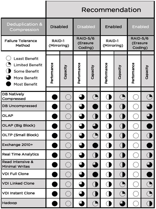
Just cite a table of the recommendations of VMware:
The vSAN supports Stretched Cluster mode (stretched cluster) with coverage of 2 geographically dispersed sites (sites), while the shared vSAN storage pool is also distributed between sites. Both sites are active, in case of failure of one of the sites, the cluster uses the storage and computing power of the remaining site to resume the work of the failed services.
A detailed look at the features of Stretched Cluster is beyond the scope of this publication.
" Documentation vSAN 6.5 on the vSphere 6.5 the Documentation the VMware Center
" in design and scale VSAN Guidelines 6.2
" Design Guide Network VSAN 6.2
" optimization technology VSAN capacity 6.2
" Striping in a VSAN
" the VMware Blog on VSAN
Virtual SAN Concept
VMware Virtual SAN (hereinafter referred to as vSAN) is a distributed software storage system (SDS) for organizing a hyper-convergent infrastructure (HCI) based on vSphere. vSAN is built into the ESXi hypervisor and does not require the deployment of additional services and service VMs. vSAN allows you to combine local host media into a single storage pool, providing a given level of fault tolerance and providing its space for all hosts and cluster VMs. Thus, we get the centralized storage necessary to reveal all the possibilities of virtualization (vSphere technology), without the need to implement and maintain a dedicated (traditional) storage system.
vSAN is started at the vSphere cluster level, it is enough to start the corresponding service in cluster management and provide it with local storage media of the cluster hosts - in manual or automatic mode. vSAN is built into vSphere and tightly attached to it, as a standalone SDS product that can work outside of the VMware infrastructure, cannot exist.
Analogues and vSAN competitors are: Nutanix DSF (Nutanix distributed storage), Dell EMC ScaleIO, Datacore Hyper-converged Virtual SAN, HPE StoreVirtual. All these solutions are compatible not only with VMware vSphere, but also with MS Hyper-V (some with KVM), they require installation and launch of a service VM on each HCI host required for SDS operation; they are not embedded in the hypervisor.
')
An important property of any HCI, incl. VMware vSphere + vSAN, is the horizontal scalability and modularity of the architecture. HCI is built and expanded on the basis of identical server blocks (hosts or nodes), combining computing resources, storage resources (local media) and network interfaces. This may be a commodity-equipment (x86 servers, including brand), supplied separately, or ready-made eplaences (for example, Nutanix, vxRail, Simplivity). Comprehensive software (for example, vSphere + vSAN + VMware__working tools) allows you to create a software-defined data center (SDDS) based on these blocks, including a virtualization environment, SDN (software-defined network), SDS, centralized management and automation / orchestra. Of course, we must not forget about the need for dedicated physical network equipment (switches), without which interaction between HCI hosts is impossible. At the same time for the organization of the network, it is advisable to use leaf-spine architecture, optimal for the data center.
The vSAN rises at the cluster level of ESXi hosts managed by vCenter and provides distributed centralized storage to the hosts of the cluster. The vSAN cluster can be implemented in 2 versions:
• Hybrid - flash drives are used as cache (cache layer), HDD provide the main storage capacity (capacity layer).
• All-flash flash drives are used at both levels: cache and capacity.
Extending a vSAN cluster is possible by adding media to existing hosts or by installing new hosts in the cluster. It should be borne in mind that the cluster should remain balanced, which means that, ideally, the composition of the media in the hosts (and the hosts themselves) should be identical. It is admissible, but not recommended, to include in the cluster hosts without media participating in the vSAN capacity; they can also place their VMs on the common storage of the vSAN cluster.
Comparing vSAN with traditional external storage systems, it should be noted that:
• vSAN does not require the organization of external storage and a dedicated storage network;
• vSAN does not require cutting LUNs and file balls, presenting them to hosts and the associated network interaction settings; after activation, vSAN immediately becomes available to all hosts in the cluster;
• vSAN data transmission is carried out according to its own proprietary protocol; standard SAN / NAS protocols (FC, iSCSI, NFS) are not needed for the organization and operation of vSAN;
• vSAN administration is performed only from the vSphere console; separate administration tools or special plug-ins for vSphere are not needed;
• do not need a dedicated storage administrator; vSAN configuration and maintenance is done by the vSphere administrator.
Media and Disk Groups
On each host of the vSAN cluster there must be at least one cache and one storage medium (capacity or data disk). These media within each host are combined into one or more disk groups. Each disk group includes only one cache medium and one or more data carriers for permanent storage.
The media given to the vSAN and added to the disk group is fully utilized, it cannot be used for other tasks or in several disk groups. This applies to both the cache carrier and the capacity of the disks.
vSAN only supports local storage media or drives connected via DAS. Inclusion of storage connected via SAN / NAS to the vSAN storage pool is not supported.
Object Storage
vSAN is an object storage, the data in it is stored in the form of “flexible” (flexible) containers called objects. The object stores within itself data or meta-data distributed across the cluster. The following are the main types of vSAN objects (created separately for each VM):
Thus, the data of each VM is stored on the vSAN as a set of objects listed above. In turn, each object includes a set of components distributed across the cluster depending on the selected storage policy and the amount of data.
Storage management on vSAN is implemented using the SPBM (Storage Policy Based Management) mechanism, which affects all vSphere repositories starting with version 6. The storage policy sets the number of allowable failures (Number of failures to tolerate), the fault tolerance method (replication or erasure coding) and the number of stripes for the object (Number of disk stripes per object). The number of stripes specified by the policy determines the number of data carriers (capacity) over which the object will be spread.
Binding a policy to a specific VM or its disk determines the number of object components and their distribution across the cluster.
vSAN allows changing storage policy for hot-on objects without stopping VM operation. At the same time in the background the processes of reconfiguration of objects are launched.
When objects are distributed across a cluster, vSAN controls that components related to different object replicas and witness components are distributed to different nodes or domains of failure (server rack, basket or platform).
Witness and Quorum
A witness is a service component that does not contain useful data (only metadata), its size is 2-4MB. It performs the role of a tiebreaker in determining the living components of an object in case of failures.
The quorum calculation mechanism in vSAN works as follows. Each component of the object receives a certain number of votes (votes) - 1 or more. A quorum is reached and the object is considered “alive” if its full replica is available and more than half of its votes.
Such a quorum calculation mechanism allows you to distribute the components of an object across a cluster in such a way that in some cases you can do without creating a witness. For example, when using RAID-5/6 or striping on RAID-1.
Virtual SAN datastore
After enabling the vSAN service in the vSphere cluster, the repository of the same name (datastore) appears, it can only be the only vSAN cluster. Thanks to the SPBM mechanism described above, within a single vSAN storage, each VM or its disk can get its required level of service (fault tolerance and performance) by binding to the desired storage policy.
The vSAN datastore is available to all hosts in the cluster, regardless of whether the host has local media included in the vSAN. At the same time, other types of storage (datastore) may be available to cluster hosts: VVol, VMFS, NFS.
vSAN datastore supports Storage vMotion (hot disk migration of VMs) with VMFS / NFS storage.
Within a single vCenter server, you can create multiple vSAN clusters. Storage vMotion between vSAN clusters is supported. In this case, each host can be a member of only one vSAN cluster.
VSAN compatibility with other VMware technologies
vSAN is compatible and supports most VMware technologies, including requiring shared storage, in particular: vMotion, Storage vMotion, HA, DRS, SRM, vSphere Replication, snapshots, clones, VADP, Horizon View.
vSAN does not support: DPM, SIOC, SCSI reservations, RDM, VMFS.
VSAN hardware requirements
Storage Requirements
Media, controllers, as well as drivers and firmware must be certified for vSAN and displayed in the appropriate VMware compatibility sheet (Virtual SAN section in VMware Compatibility Guide).
SAS / SATA HBA or a RAID controller can be used as a storage controller, they should function in passthrough mode (disks are sent by the controller as is, without creating a raid array) or raid-0.
SAS / SATA / PCIe –SSD and NVMe carriers can be used as cache carriers.
SAS / SATA HDD for hybrid configuration and all flash types listed above (SAS / SATA / PCIe –SSD and NVMe) for all-flash configuration can be used as data carriers.
RAM and CPU requirements
The amount of host memory is determined by the number and size of disk groups.
The minimum amount of host RAM for participating in a vSAN cluster is 8GB.
The minimum amount of host RAM required to support the maximum configuration of disk groups (5 disk groups of 7 data carriers) is 32GB.
vSAN utilizes about 10% of processor resources.
Network requirements
Dedicated 1Gb / s adapter for hybrid configuration
Dedicated or shared 10Gbps adapter for all-flash configuration
You must allow multicast traffic on the vSAN subnet
Bootable media
Local USB or SD media can be used to boot hosts with vSAN, as well as SATADOM. The first 2 types of media do not save logs and traces after a reboot, since they are written to a RAM disk, and the last one is saved, therefore it is recommended to use SATADOM SLC-class media with greater survivability and performance.
VSAN 6.5 Configuration Max
Maximum 64 hosts per vSAN cluster (for both hybrid and all-flash)
Maximum 5 disk groups per host
Maximum 7 capacity-carriers per disk group
No more than 200 VMs per host and no more than 6000 VMs per cluster
No more than 9000 components per host
Maximum disk size VM - 62TB
The maximum number of carriers in the stripe on the object - 12
Technological features of VMware Virtual SAN
VSAN cluster planning
The minimum number of vSAN cluster hosts is determined by the number of acceptable failures (the Number of failures to tolerate parameter in the retention policy) and is determined by the formula: 2 * number_of_failures_to_tolerate + 1.
Under the condition of 1 failover, vSAN allows the creation of 2x and 3x node clusters. The object and its replica are located on 2 hosts, the witness is placed on the 3rd meter. The following restrictions appear:
• if 1 host is dropped, there is no possibility of data rebuild to protect against a new failure;
• when transferring 1 host to maintenance mode, there is no possibility of data migration, the data of the remaining host at this time become unprotected.
This is due to the fact that there is simply nowhere to rebuild or migrate data, there is no additional free host. Therefore, it is optimal if the vSAN cluster is used from 4 hosts.
Rule 2 * number_of_failures_to_tolerate + 1 is applicable only when Mirroring is used for fault tolerance. When using Erasure Coding, it does not work, it is described in detail below in the section “Providing fault tolerance”.
In order for a vSAN cluster to be balanced, the hardware configuration of the hosts, first of all, for media and storage controllers, must be identical.
An unbalanced cluster (different configuration of disk groups of hosts) is supported, but it forces us to put up with the following disadvantages:
• non-optimal cluster performance;
• Uneven utilization of host capacity;
• differences in host maintenance procedures.
Allocation of a VM with a vCenter server to a vSAN datastor is allowed, however this leads to risks associated with managing the infrastructure in case of problems with vSAN.
VSAN cache planning
It is recommended to plan the cache size with a margin for the possibility of expanding the capacity level.
In the hybrid configuration, 30% of the cache is allocated for writing and 70% for reading. All-flash vSAN configuration uses the entire capacity of the write cache media, no read cache is provided.
The recommended cache size should be at least 10% of the real VM capacity before replication, i.e. the usable space is taken into account, but not really occupied (taking into account replication).
In a hybrid configuration, a disk group will utilize the entire capacity of the flash media installed in it, while its maximum capacity is unlimited.
In the all-flash configuration, the disk group cannot use more than 600GB of capacity of the installed flash media, while the remaining space will not be idle, since the cached data will be recorded cyclically over the entire volume of the media. In all-flash vSAN, it is advisable to use flash drives for cache with higher speed and lifetime compared with capacity-carriers. The use of more than 600GB of cache under the cache will not affect the performance, but it will extend the service life of these media.
This approach to cache organization in all-flash vSAN is due to the fact that flash capacity carriers are fast, so there’s no point caching reading. Allocating all the write cache capacity, except for its acceleration, allows you to extend the capacity-level lifetime and reduce the overall cost of the system, since you can use cheaper media for permanent storage, while one more expensive, productive and durable flash cache will protect them from unnecessary write operations.
Fault tolerance
The fault tolerance of the VM and the ratio of the amount of useful and occupied vSAN storage space are determined by two storage policy parameters:
• Number of failures to tolerate - the number of allowable failures, determines the number of cluster hosts whose failure will be able to survive the VM.
• Failure tolerance method - fault tolerance method.
vSAN offers 2 fault tolerance methods:
• RAID-1 (Mirroring) - full replication (mirroring) of an object with replica placement on different hosts, an analogue of network raid-1. Allows you to survive a cluster of up to 3 failures (hosts, disks, disk groups or network problems). If Number of failures to tolerate = 1, then 1 replica is created (2 instances of the object), the space actually occupied by the VM or its disk on the cluster is 2 times more than its useful capacity. If Number of failures to tolerate = 2, we have 2 replicas (3 instances), the actual occupied volume is 3 times more than the useful one. For Number of failures to tolerate = 3, we have 3 replicas, occupying space 4 times more useful. This fault tolerance method does not use space efficiently, but provides maximum performance. Can be used for hybrid and all-flash cluster configuration. The minimum required number of hosts is 2-3 (for practicing 1 failure), the recommended minimum is 4 hosts, which makes it possible to rebuild upon failure.
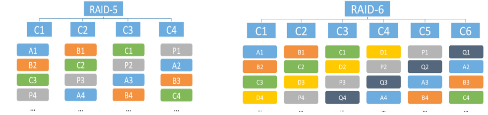
• RAID-5/6 (Erasure Coding) - when placing objects, parity blocks are computed, analogous to network raid-5 or -6. Only all-flash cluster configuration is supported. Allows the cluster to work 1 (analog raid-5) or 2 failure (analog raid-6). The minimum number of hosts for testing 1 failure is 4, for testing 2 failures is 6, the recommended minimum is 5 and 7, respectively, for the possibility of rebuild. This method allows you to achieve significant savings in cluster space compared to RAID-1, however, it leads to a loss of performance, which can be quite acceptable for many tasks, considering all-flash speed. So, in the case of 4 hosts and a tolerance of 1 failure, the usable space occupied by the object when using Erasure Coding will be 75% of its total volume (for RAID-1, we have 50% of the usable space). In the case of 6 hosts and the admission of 2 failures, the usable space occupied by the object when using Erasure Coding will be 67% of its total volume (for RAID-1, we have 33% of usable space). Thus, RAID-5/6 in these examples turns out to be more efficient than RAID-1 in using cluster capacity by 1.5 and 2 times, respectively.
Below is the distribution of data at the component level of the vSAN cluster using RAID-5 and RAID-6. C1-C6 (first line) - components of the object, A1-D4 (color blocks) - data blocks, P1-P4 and Q1-Q4 (gray blocks) - parity blocks.
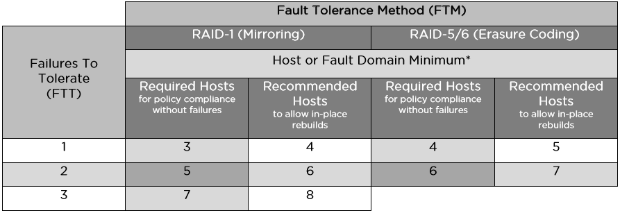
vSAN allows you to provide fault tolerance for different VMs or their disks in different ways. Within a single repository, you can bind policies with mirroring for performance-critical VMs, and for less critical VMs you can configure Erasure Coding to save space. Thus, there will be a balance between performance and efficient use of capacity.
Below is a table with the minimum and recommended number of hosts or failure domains for the various FTM / FTT options:
Failure domains
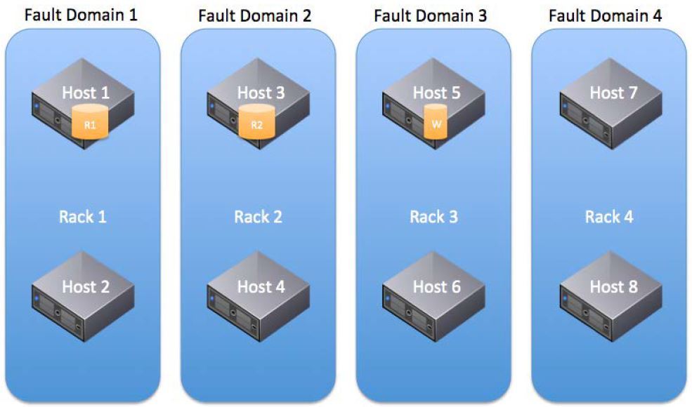
vSAN introduces the concept of fault domains to protect a cluster from failures at the level of server racks or baskets, which are logically grouped into these domains. The inclusion of this mechanism leads to the distribution of data to ensure their fault tolerance not at the level of individual nodes, but at the domain level, which will make it possible to survive the failure of an entire domain — all nodes grouped in it (for example, the server rack), since replicas of objects will necessarily be placed on nodes from different failure domains.
The number of failure domains is calculated according to the formula: number of fault domains = 2 * number of failures to tolerate + 1. The vSAN requires at least 2 failure domains, each with 1 or more hosts, but the recommended number is 4, since it allows for rebuild in case of a failure (2-3 domains do not allow rebild, nowhere). Thus, the method of counting the number of failure domains is similar to the method of counting the number of hosts to work out the necessary number of failures.
Ideally, in each domain of failure, there should be the same number of hosts, hosts should have identical configuration, it is recommended to leave the space of one domain empty to allow rebuilds (for example, 4 domains with 1 failure).
The failure domain mechanism works not only for Mirroring (RAID-1), but also for Erasure Coding, in this case each component of the object must be located in different failure domains and the formula for calculating the number of failure domains changes: at least 4 domains for RAID-5 and 6 domains for RAID-6 (similar to calculating the number of hosts for Erasure Coding).
Deduplication and compression
The deduplication and compression (CD) mechanisms are supported only in the all-flash configuration and can be enabled only on the vSAN cluster as a whole, selective switching on for individual VMs or disks using policies is not supported. Using only one of these technologies won't work either, just both.
Turning on the DIC makes objects automatically strip on all the disks in the disk group, it allows you to avoid rebalancing the components and to detect the coincidence of data blocks from different components on each disk in the disk group. At the same time, it is still possible to manually set the objects at the level of storage policies, incl. beyond the limits of the disk group. When DIS is turned on, it is not advisable to reserve space for objects at the policy level (the parameter Object Space Reservation, thick disks), since this will not give an increase in performance and will adversely affect the space savings.
Dis produced after confirmation of the write operation. Deduplication is performed before unloading data from the cache over the same 4K blocks within each disk group; deduplication between disk groups is not performed. After deduplication and before unloading data from the cache, they are compressed: if you actually compress 4K to 2K or less, then compression is performed, if not, the block remains uncompressed to avoid unnecessary overhead.
In deduplicated and compressed form, the data is only at the storage level (capacity), which is approximately 90% of the cluster data volume. At the same time, overhead costs for D & S make up about 5% of the total capacity of the cluster (storage of metadata, hashes). In the cache, the data is in its normal state, since writing to the cache is performed much more often than in the permanent storage, respectively, the overhead and performance degradation from DIC in the cache would be much more than the bonus from optimizing its relatively small capacity.
It should be noted that there is a question of choosing between a small number of large disk groups or many small ones. On large disk groups, the effect of DIS will be greater (it is done inside groups, not between them). For many small disk groups, the cache works more efficiently (its space increases due to an increase in the total number of cache carriers), there will be more failure domains, which will speed up the rebuild if one disk group fails.
The space occupied by snapshot chains is also optimized by D & C.
Stripping objects and the number of components
The storage policy parameter Number of disk stripes per object sets the number of individual capacity-carriers over which the components of one object replica (VM disk) will be distributed. The maximum value of this parameter, which means the maximum length of the stripe that vSAN supports, is 12, in this case the object replica is distributed to 12 carriers. If the specified stripe length exceeds the number of carriers for the disk group, then the object replica will be stretched over several disk groups (most likely within 1 host). If the specified stripe length exceeds the number of host media, then the object replica will be stretched over several hosts (for example, all media of one host and some of the media of the other).
By default, the stripe length is set to 1, which means that no striping is performed and the replica (up to 255GB) is placed on 1 media as 1 component.
Theoretically, striping can give a performance boost due to parallelization of I / O, if the media on which the object is stripped is not overloaded. Object striping on several disk groups allows to parallelize the load not only on capacity-carriers, but also to utilize the cache resources of the disk groups involved. VMware recommends to leave the parameter “number of stripes per object” equal to 1, as set by default, and not to strip objects, except in cases where striping, for example, is necessary and will actually improve performance. In the general case, it is considered that striping of a tangible increase in productivity will not be able to give. In hybrid configurations, the effect of striping can be positive, especially with intensive reading when there are problems with getting into the cache. Streaming recording can also be accelerated by striping, incl. in all-flash configurations, since several cache-carriers can be utilized and data are wiped out onto permanent media.
It should be noted that striping leads to a significant increase in the number of cluster components. This is important for clusters with a large number of VMs and objects, when the limit of components per cluster (9000) can be exhausted.
It is necessary to take into account that the maximum size of 1 component of an object is 255GB, which means that if an object is large, its replica will be automatically divided into a number of components, a multiple of 255. In this case, regardless of the striping policy, the replica components will be split across several media. if there are a lot of them (more than the media on the host or in the cluster, for example, we create a 62TB disk), then several components of one object can fall on the media.
VSAN cluster capacity planning
When planning the storage size of a vSAN cluster, it is necessary to take into account that the actual space occupied, taking into account the fault tolerance methods used (mirror or EC) and the number of allowable failures (from 1 to 3x), can significantly exceed the useful capacity of the cluster. It is also necessary to consider the impact of methods for optimizing the use of space (EC and DIS).
You should consider the allocation of space for swap-files (the size of the RAM of each VM) and the storage of snapshots.
When filling the vSAN capacity by 80%, the rebalancing of the klastra begins - this is the background process that redistributes the data across the cluster and causes a significant load, it is better not to allow it to occur. About 1% of the space goes when formatting the cluster media under the vSAN file system (VSAN-FS). A small portion of the space is spent on D & C metadata (5%). Therefore, VMware recommends designing a vSAN cluster with a reserve of 30% capacity in order not to bring it to rebalancing.
Choosing a storage controller
vSAN recommends and supports the use of multiple storage controllers on a single host. This allows you to increase performance, capacity and fault tolerance at the level of individual nodes. At the same time, no vSAN ready node contains more than 1 storage controller.
It is recommended to choose controllers with the longest queue length (at least 256. It is recommended to use controllers in pass-through mode, when disks are directly presented to the hypervisor. VSAN supports using controllers in raid-0 mode, but their use leads to additional manipulations with tracking (for example, when replacing media. It is recommended to disable the internal controller cache, if not, then set 100% for reading; proprietary acceleration modes for the controllers should also be disabled.
Failover
In case of capacity-carrier failure, its rebuild can be made inside the same disk group or to another group (on the same host or on another), this depends on the availability of free space.
Failure of the cache carrier leads to the entire disk group rebuild. Rebuilds can be made to the same host (if there are disk groups and free space on it) or to other hosts.
In case of failure of the host for Rebuild, it is better to provide at least 1 free host, if you need to work out a few failures, then there should be several free hosts.
If a component (disk or disk controller) is degraded (the component’s failure can be restored), then vSAN starts to rebuild it immediately.
If a component (network loss, network card failure, host disconnection, disk disconnection) is absent (temporary disconnection with the possibility of recovery), then vSAN starts to rebuild it deferred (by default, after 60 minutes).
Naturally, the rebuild condition is the availability of free space in the cluster.
After a failure (carrier, disk group, host, network loss), vSAN stops i / v for 5-7 seconds while evaluating the availability of the lost object. If the object is located, then the I / O resumes.
If 60 minutes after the host fails or the network is lost (the rebuild started), the lost host returns to service (the network is restored or raised), the vSAN itself determines what is better (faster) to do: finish the rebuild or synchronize the returned host.
Checksums
By default, vSAN calculates checksums to control the integrity of objects at the retention policy level. The checksums are calculated for each data block (4KB), they are checked as a background process on read operations and for data that remains cold during the year (scrubber). This mechanism allows you to detect data corruption for software and hardware reasons, for example, at the level of memory and disks.
When a checksum inconsistency is found, the vSAN automatically recovers the damaged data by overwriting it.
Checksum calculation can be disabled at the retention policy level. The scrubber start-up frequency (check of blocks to which there were no calls) can be changed in the advanced settings (VSAN.ObjectScrubsPerYear parameter) if desired and perform this check more often than once a year (at least once a week, but additional loading will occur).
VSAN network planning
vSAN supports nic-teaming with port aggregation and load balancing.
Up to version 6.5 inclusive, vSAN requires multicast traffic support on its network. If several vSAN clusters are located on the same subnet, it is necessary to assign different multicast addresses to their hosts in order to separate their traffic. Starting from version 6.6, vSAN does not use multicast.
When designing a vSAN network, it is recommended to lay a leaf-spine architecture.
vSAN supports NIOC to allocate guaranteed bandwidth for its traffic. NIOC can only be run on distributed vSwitch, vSAN allows their use in any vSphere edition (they are included in the vSAN license).
vSAN supports the use of Jumbo frames, but VMware considers the performance gain from using them to be insignificant, therefore it gives the following recommendations: if the network already supports them - you can use them, if not, they are completely optional for vSAN, you can do without them.
Example of placing objects in a vSAN cluster
Above, we described the composition, structure, and principles of placing objects and components in a vSAN cluster, methods for ensuring fault tolerance, and the use of retention policies.
Now let's look at how this works with a simple example. We have a cluster of vSAN of 4 hosts in all-flash configuration. The figure below is conditionally represented as in this cluster will be placed 3 disks VM (vDiski).
vDisk-1 was tied to a storage policy with a 1 failure (To Tolerate (FTT) = 1) and Erasure Coding (Fault Tolerance Method (FTM) = EC). Thus, the object in Disk-1 was distributed in the system in the form of 4 components, 1 per host. The data (data) of the disk within these components is recorded along with the calculated parity values (parity), in fact, it is network RAID-5.
vDisk-2 and vDisk-3 were tied to storage policies with 1 failover (FTT = 1) and mirroring (FTM = Mirror). Let's clarify that Disk-2 has a useful size of less than 255 GB and the default stripe size is set for it (Number of disk stripes per object = 1). Therefore, the disk-2 object was placed on the cluster in the form of 3 components on different nodes: two mirror replicas and a witness.
Disk-3, in this case, has a useful size of 500GB and the default stripe size is set for it. Since 500GB is more than 255GB, vSAN automatically splits one replica of the object Disk-3 into 2 components (Component 1-1 and Component 1-2) and puts it on Host-1. Their replicas (Component2-1 and Component4-2) are hosted on hosts 2 and 4, respectively. In this case, there is no witness, since the quorum calculation algorithm using votes allows you to do without it. It should be noted that vSAN placed vDisk-3 on the cluster space in this way automatically and at its discretion, it’s impossible to set it up with your hands. With the same success, she could place these components on nodes in a different way, for example, one replica (Component 1-1 and Component 1-2) on Host-4, the second on Host-1 (Component 2-1) and Host-3 (Component 4- 2).Or it could allocate 2 hosts for the replicas (2 components on Host-1 and 2 components on Host-3), and on the third place a witness (Host-4), this is already 5 components, not 4.
Of course, automatic placement of objects is not arbitrary, vSAN is guided by its internal algorithms and tries to evenly utilize the space and, if possible, reduce the number of components.
Placing vDisk-2 could also be different, the general condition is that the components of different replicas and the witness (if any) must be located on different hosts, this is a failover condition. So, if Disk-2 had a size slightly less than 1.9TB, then each of its replicas would consist of 8 components (one component is not more than 255GB). Such an object could be placed on the same 3 hosts (8 components 1 replicas on Host-1, 8 components 2 replicas on Host-2, a witness on Host-3. Or vSAN could place it without a witness, distributing 16 components of both replicas across all 4 hosts (without intersecting different replicas on the same host)
Recommendations for efficient use of space
Just cite a table of the recommendations of VMware:
Stretched Cluster Mode Support
The vSAN supports Stretched Cluster mode (stretched cluster) with coverage of 2 geographically dispersed sites (sites), while the shared vSAN storage pool is also distributed between sites. Both sites are active, in case of failure of one of the sites, the cluster uses the storage and computing power of the remaining site to resume the work of the failed services.
A detailed look at the features of Stretched Cluster is beyond the scope of this publication.
List of sources used (useful links)
" Documentation vSAN 6.5 on the vSphere 6.5 the Documentation the VMware Center
" in design and scale VSAN Guidelines 6.2
" Design Guide Network VSAN 6.2
" optimization technology VSAN capacity 6.2
" Striping in a VSAN
" the VMware Blog on VSAN
Source: https://habr.com/ru/post/318980/
All Articles