Comparison of signal recognition methods. Neural networks against matched filter
I recently published an article "Recognition of radio signals using neural networks" [1]. And there was quite a long and interesting discussion about the possibility of using an agreed filter (SF) for these purposes. Of course, using matched filters for the task that was solved is problematic. But I was interested in another question, that it is better to use with minor fluctuations of signal parameters, neural networks (NA) or SF. As a signal generator I will use a conventional multivibrator. I will give a signal through a sound card, and then recognize it using the method described in [1] and using a matched filter. Then the software will compare the results and give the answer which method is better.
Part 1. Signal generator
In order for the comparison to be adequate, we will recognize the REAL signal. To create it you need a generator. You will also need a noise generator. The signal will be generated using a multivibrator. And to "not climbed" the HF components on the output must be put the low-pass filter. Powered by USB. The range of the supplied voltage to the audio card should be between 0.001 - 1.5V. And the output from the multivibrator is from 0 to 5V. To limit the voltage will use the L-shaped divider. Below is a schematic diagram of the generator.
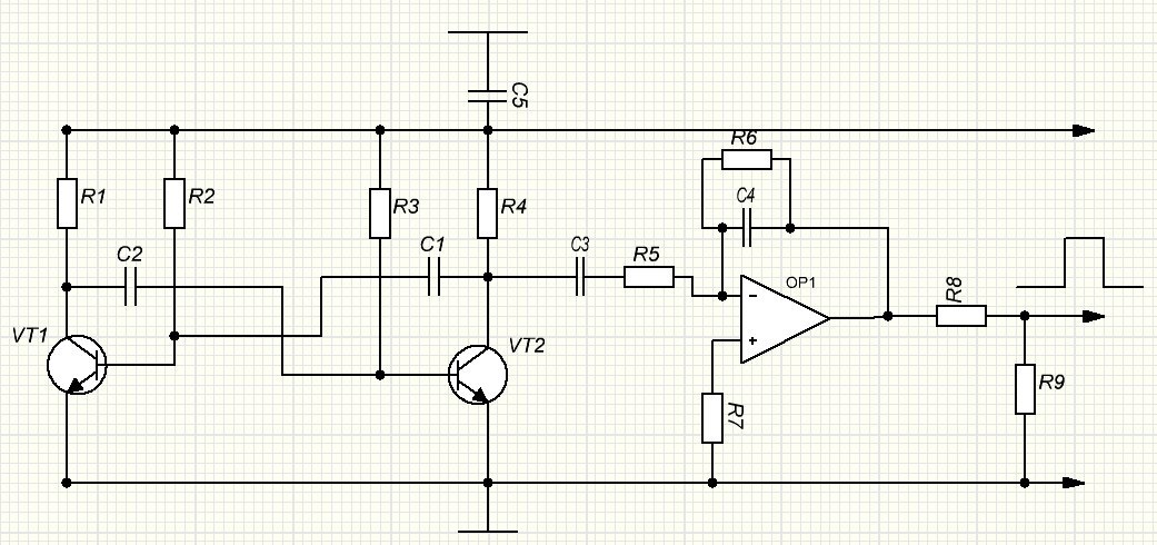
I didn’t do it from scratch because in the second year, in the framework of the hackathon, he assembled a cardio preamplifier for the removal of the cardiointervalogram, which differs only in the absence of a PIC between two stages. Therefore, I limited myself to adding this link. That's what happened in the end.
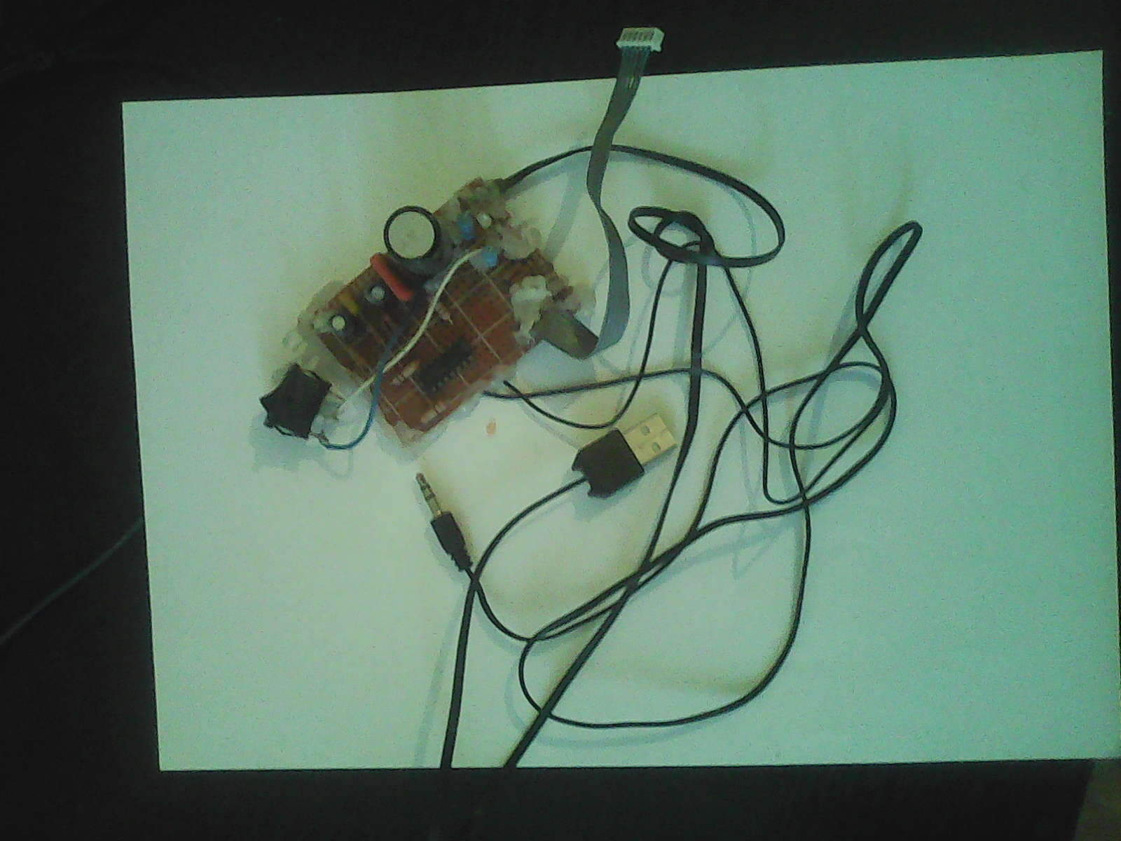
Appearance:
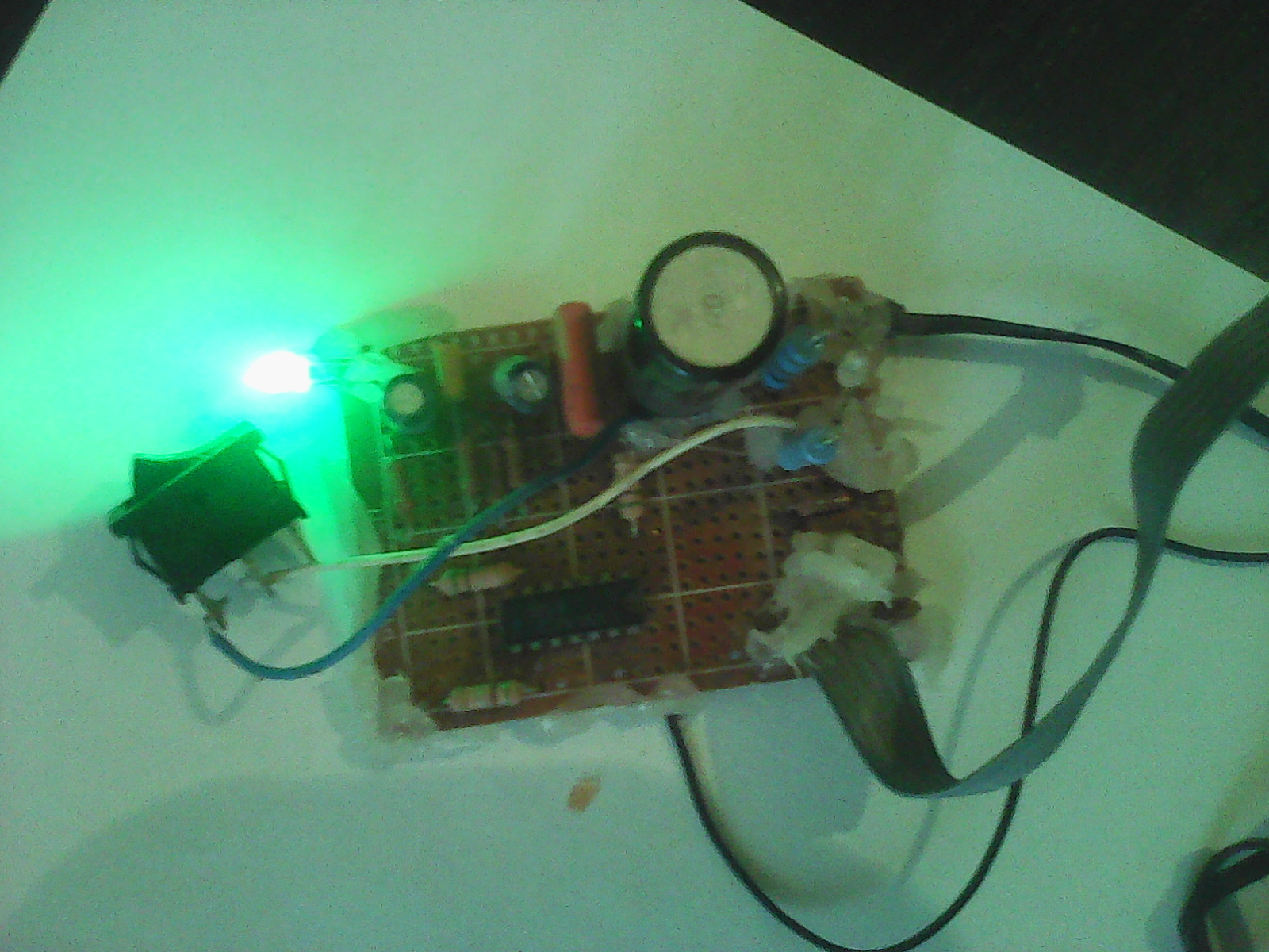
During work:
As a white noise generator, I used the randNorm method from my mat. AI.MathMod libraries for C #.
Part 2. Signal Reception
To receive and record a signal, I used the NAudio library for the C # language. Next you need to create a class to record the signal. At the beginning we include namespaces.
using System; using System.Collections.Generic; using NAudio.Wave; using AI.MathMod.AdditionalFunctions; using AI.MathMod; We declare global variables:
// WaveIn - WaveIn waveIn; // List<double> lf2 = new List<double>(); // double fd = 500, // timeRec = 5; // Vector signal = new Vector(); // public Vector Signal { get{return signal;} } // public Vector Time { get{return MathFunc.GenerateTheSequence(0,signal.N)/fd;} } And the method to start recording (taken from here ):
void Start(){ try { waveIn = new WaveIn(); // ( ) waveIn.DeviceNumber = 0; // DataAvailable , waveIn.DataAvailable += waveIn_DataAvailable; // waveIn.RecordingStopped += new EventHandler<StoppedEventArgs>(waveIn_RecordingStopped); // wav- - - ( mono) waveIn.WaveFormat = new WaveFormat(fd,16,1); // waveIn.StartRecording(); } catch{} } The record itself:
// void waveIn_DataAvailable(object sender, WaveInEventArgs e) { if (this.InvokeRequired) { this.BeginInvoke(new EventHandler<WaveInEventArgs>(waveIn_DataAvailable), sender, e); } else { lf2.Clear(); for (var i = 0; i < e.Buffer.Length; i += 2) { double sample = BitConverter.ToInt16(e.Buffer, i) / 32768.0; lf2.Add(sample); } signal.Add(lf2.ToArray()); if(signal.N>=(timeRec*fd)) Stop(); // } } Part 3. Matched Filter
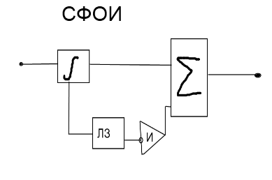
Now you need to create a model of a consistent filter. The matched filter (SF) provides the maximum SNR (signal-to-noise ratio) in case the filter is matched with the desired signal, i.e. The frequency response of the filter coincides with the modulus of the spectral density of the signal. The SF consists of a matched filter for a single pulse (SFDI), delay lines (LZ) and an adder. The SFOR for a rectangular pulse consists of an integrator, LZ, an inverter and an adder (for a radio pulse with a rectangular envelope, the integrator is replaced by a radio integrator, which is often a band-pass filter, in particular, an oscillator circuit or a resonant amplifier with an oscillator circuit in the collector circuit). Below is a block diagram. The increase in the SNR is due to the fact that the signal is narrowband and the interference is wideband. [2]
Also, the drive gives an increase in SNR in times where m is the number of pulses in a packet. Due to the high cost and complexity of the implementation of LZ, in real-life problems, they increasingly use the method with digital accumulation. Then the probability of a false alarm and correct detection is given by the following relations:
The structure of the drive (all kouf. "A" = 1):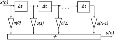
Schematically, the operation of the drive is presented below:
Due to the fact that the pulse repetition periods are equal, as well as the pulse duration, you can use only one delay line instead of a set of so-called recirculators with a drive. [3]
In our case, perfect, without loss. Structural diagram of the Federation Council.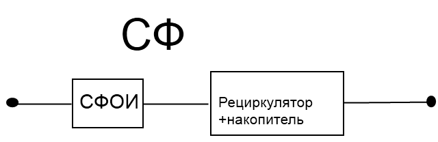
You can read more about the structure and calculations of the SF in [2 pp. 415 - 427] and [3 p. 563 - 598].
When the probability of finding there a signal> 0.6, it is decided that the signal is registered.
Part 4. Comparison Software
The program architecture in its structure contains "two flags",
bool flag1 = false; bool flag2 = false; when the program starts, both of them are inactive, there is a method that every time the window is polled checks whether the flags are active, if the first flag is active, 1 point is credited to the matched filters. If the second, then the score is credited to the neural network. In any case, all parameters are returned to their original position.
Total
Twenty experiments were carried out in which a matched filter tuned to the signal under investigation, SNR = 0.4, was used; the result was 16: 4 in favor of the SF. After that, the signal duration was changed by 5%, the result: 2:18 in favor of the National Assembly. From this we can conclude that with the known parameters, the SF does much better than the ANN, but when the parameters are not known, or can vary, it is more expedient to use the ANN.
Literature:
- Recognition of radio signals using neural networks .
- Baskakov S.I. Radio circuits and signals. M .: Higher school, 2nd edition.
- Gonorovsky I.S. Radio circuits and signals. M .: Drofa, 5th edition. 2006
')
Source: https://habr.com/ru/post/318886/
All Articles