Drawing vector graphics - triangulation, rasterization, anti-aliasing and new scenarios
Back in 2013, the game Tiny Thief came out, which caused a lot of noise in the mobile Flash (AIR) development environment due to the rejection of raster graphics in builds, including animation atlases and other things - everything that was in the assembly was stored in a vector format directly from the Flash editor .
This made it possible to use a huge amount of unique content and save the size of the installation file up to ~ 70 megabytes (* .apk file from Google Play). More recently, there was an interest in the topic of drawing vector graphics on mobile devices (and in general on the topic of vector drawing with hardware support), and I was surprised at the lack of information at the initial level on this topic. This is an overview article on possible vector drawing methods and already existing solutions, as well as on how such things can be done independently.

Main way
Vector drawing is most often approached in the following way: they take all the shapes, curves and other things, they are traversed by the triangulation algorithm (separation of closed contours into triangles), assuming various kinds of strokes and lines are similarly filled objects, and get some approximate representation of the described mathematical figure formula.
That is, the vector circle drawn in this way will actually be a polygon. The quality criterion in this case will be the number and size of the triangles obtained in the end:

From left to right -
- Inkscape source
- the result of triangulation with a low number of triangles,
- resulting triangles
The reason for such workarounds is simple - the graphics card is able to work effectively only with vertices, triangles and pixels (there is a slightly different story about GPGPU, but in this context it is worth mentioning in passing). If you draw mathematically correct representations of models using the CPU, then it will take much more time. Therefore, we simply triangulate and send the graphics card to render in raw form as is.
Underwater rocks
Such crude drawing of triangles leads to the appearance of an aliasing effect - gradation of the edges of the image (this is clearly seen in the screenshot above). This problem is inherent in any opaque geometry, represented in the form of triangles.
If you look at the screenshot of Tiny Thief, then it is immediately obvious that the game is devoid of this drawback - the edges of the objects are beautifully smoothed.


Field study
I checked all the things described below with the help of Adreno Profiler, NVIDIA PerfHUD ES and Unity (testing the suggested solutions).
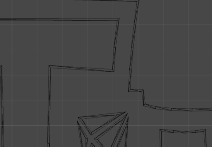
This is what Adreno Profiler shows if you enable the color grid mode:

That is drawing by that method of a triangulation. Vertices are painted directly without textures (the color parameter of the vertices).
Here's what's in the alpha buffer (obviously, Adreno GPU has such a thing as an “alpha buffer”):

There is a thin single-pixel strip along the edges of the objects. Interestingly, on the edges between neighboring objects (white background-colored letter) alpha channel is “white”, that is, the entire logo is drawn in one pass, and smoothing inside such objects is implemented in a slightly different way.
Shader:
{ lowp vec4 fcolor; // color fcolor = color; // , factor fcolor.a *= factor.a; fcolor = fcolor; gl_FragColor = fcolor; } The essence of smoothing is more or less clear - with triangulation, we add a thin set of triangles along the edge of the object.
No matter how much I tried to zoom in, I couldn’t see these cunning thin triangles. But, fortunately, Adreno Profiler, unlike PerfHUD, allows you to export geometry in text form.
Assembly in pieces
Having written a simple parser, it turned out to restore the original mesh in Unity. But a strange picture was waiting for me:

Frames without smoothing. In the grid view mode, the filling triangles are also not visible:
For a long time I could not understand what was the matter. It turned out that the filling triangles are turned in the other direction. This becomes visible when looking at the logo on the other side:

It is also noticeable that there are empty lines between the elements of the logo, which are filled with gradients (the gradient is made by painting the vertices in the corresponding colors), and there is no smoothing.

')
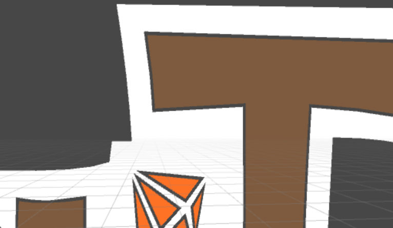
If we remove the backface culling in the shader, we get what we wanted to get in the end:

But an interesting feature arises - if you bring this object closer to the camera, then anti-aliasing becomes too noticeable and looks like a blur:

That is, triangulation occurs every time in place, depending on the screen size, and does not imply a change in the size of this object. The size of the triangles is calculated so that the total width is one screen pixel or less.
Almost all objects on the screen are drawn in the same way. The exception is the background, which is rendered once in texture.
Statistics
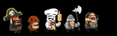
It is interesting enough to see a summary of the drawing of characters, on average, each character (guard, cook) in a triangulated form is about 3-4 thousand triangles. This is about as good quality low-poly 3D model. The grid is so dense that it seems that the object is drawn with a texture:
The logo occupies almost 9 thousand triangles. The average number of draw calls on average is about a hundred (it would be much more if the background was not drawn as a texture), but the FPS is consistently maximum even on the old ZTE V811 (Beeline Smart 2).
In general, while we take the first (and main) way of drawing vector graphics into the piggy bank:
we triangulate our vector image, make a thin border along the joints with intermediate colors, and at the edges make a thin translucent strip.
Turn upside down
SDF
If you set a limit on the number of colors of a vector image, then you can take a completely different path. Suppose that we have a simple vector single-color icon:

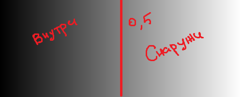
It can be “squeezed” almost without loss of quality using the Signed Distance Field. The bottom line is that we do not store the texture itself, but information about the distance of pixels to the border of the icon. The value at the border is usually considered to be 0.5. Anything more is considered an "inside" icon. Anything less is "outside." In fact, it does not matter which way the border is outweighed - sometimes you can make less than 0.5 inside and more than 0.5 outside. For clarity (black icons on a white background) I will show just such an option.
The dice so spread out looks like this:

The difference from the usual blur is that by finding the minimum distance between the current pixel and the border, in any case, we will calculate the distance along the normal (the minimum distance from the point to the line is always determined by the perpendicular). That is, the gradients on the texture describe the direction of the normal to the nearest border.

On the Internet and, in particular, on Habré there are a lot of articles about SDF, I will give them at the end of the article.
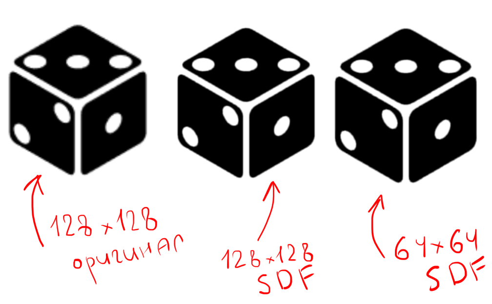
The picture clearly shows the difference in quality between a regular texture and two variants of SDF. When you increase the usual images are clearly visible blur. By increasing the SDF texture, we will in any case get sharp boundaries. Moreover, even having reduced the size of the texture by half, the presence of artifacts remains almost imperceptible (you can write a separate article about increasing the quality of the raw SDF texture). Artifacts, in contrast to the usual texture, appear as a smoothed ladder at the beveled edges of the icon. This is due to the fact that the pixels go exactly horizontally and vertically, and as the image size decreases, the accuracy of the oblique straight approximation also decreases with the help of two perpendicular (recall that we approximate the normal vector to the boundary).
The shader for drawing will be just a little more complicated than just reading the texture. In the experiments, I tried a lot of different options, including and a variant from the article [2], in general, it looks like this:
float4 frag (v2fSDF f) : SV_Target { float2 uv = f.uv; half4 texColor = tex2D(_MainTex, uv); // - half distance = texColor.a; // half smoothing = _Smoothing; // - _Dilate = 0.5 half2 range = half2(_Dilate - smoothing, _Dilate + smoothing); // ( - ) half totalSmoothing = smoothstep(range.x, range.y, distance); half3 rgb = f.color.rgb; return float4(rgb, totalSmoothing); } It is worth noting that in this case the RBG texture channel is thrown out and is not involved in the calculations (to this we will come back later). You can adjust _ Smoothing either manually under the current size of the texture on the screen (but then there will be the same problem when enlarged, as was the case with drawing through meshes), or use the cg function fwidth , which roughly estimates the size of the current fragment relative to the screen and “adjusts "anti-aliasing under the relative size of the icon on the screen.
Since the main limitation of the SDF method is the need for "binary" (monochrome) of the original symbol, it is most often used when drawing text - by adjusting and modifying the processing options of the same SDF texture, you can create a stroke, shadow, blur, etc. [one]. A less popular way to use SDF is to draw monochrome icons (as is the case with the image of a die), but for the most part this is just a special case of a text character.
Another disadvantage of this approach is the loss of sharp edges and corners:

On the left - the original texture. Right - reduced size SDF
And another example with the text from the article [3]:

Problem solving as they become available
There are examples of the implementation of a similar algorithm that preserves sharp angles [4] [5]:

The brief essence of the algorithm is as follows:
The raw SDF rounds the corners because the farther the pixels are from it, the stronger it is rounded. This happens because the perpendicular cannot be drawn to the corner (the derivative of the function does not exist at this point) - many pixels will count the distance along the radius of the circle, the center of which is just the angle. This can be avoided by tracing all the angles of the symbol by checking the gaps with a smoothly running curve. And then, using the truth table, determine whether the quadrant of the angle should be shaded or not. That is, the corners are usually painted over with intersected SDF cards recorded in different channels, and the final pixel value is calculated by the median of the vectors from the three channels.
Of course, I can not contain the entire article on 90 pages in one paragraph, so I advise you to look at it in full [5].
There were earlier attempts to do something similar with the intersection of various fields scattered across the channels, but some options do not suggest the presence of tricky possibilities of adding shadow, stroke, or increasing the thickness of the symbol, unlike the example described (due to the fact that distance fields per se).
Less channels - more accuracy.
There is a companion on Twitter who does something like this by hook or by crook, but with one channel:

If you look at the various links on his twitter , you can stumble upon some options for implementation. As I understand it, the approach differs from the standard SDF in that the actual distance to the borders is not used (to avoid that rounding around the corner-center), but a slightly reinterpreted figure is used, the corners of which continue further. This eliminates both the rounding of corners and several channels, simplifying the shader, and reducing the total amount of information required to represent such shapes.
This comrade also has a shader that reads the distance field for the bezier curve on the GPU in real time, but it requires desktop computing power even for one curve (which is set parametrically and its formula lies "right in the shader"). If you twist the settings and code, you can see the distance field itself without shading and modulation:
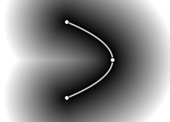
The general essence of these methods lies in the analysis of the curve defining the character boundaries.
Back to basics
You can also go the third way - not to store raster information about any symbol, but to draw, so to speak, “from the oven” - directly from the vector representation of the curves. The problem is that it is relatively difficult to transfer information about curves to a graphics card without loss of performance. There are several articles describing similar methods:
GPU text rendering with vector textures [3], and Microsoft even has a patent .
In short, the essence is as follows:
We divide the symbol into cells, for each cell we make a map of the intersection of the curves with the rays, fired at different angles and intersecting this cell. We look at the number of intersections and the distance at which these intersections occur. Curve data is stored in the form of a crumpled texture, in which the coordinates of the bezier curves are given. One bezier curve is 3 or 4 parameters depending on the degree of this curve. Above the 4th parameter, curves are usually not taken. The shader is concerned with the fact that, depending on the current cell being drawn and the texture parameters present on this cell, it reads the necessary pixels from the reference texture and uses them to reconstruct the analytical view of the curve on the GPU.
Not everything is so rosy.
The disadvantage of these approaches is the use of a relatively large number of texture read operations. I once dealt with realtime shadow rendering with a tap blur blur on mobile devices, and any Dependent Texture Reads (DTS - I did not find a generally accepted analogue in Russian) significantly impaired performance. If it is very rough - DTS occurs when the read coordinates of the texture are known only in the fragment shader, that is, directly when the pixel is drawn. Usually, a high speed of reading a texture in a fragment shader is caused by the fact that a particular interpolated texture coordinate of a pixel becomes known immediately after the vertex shader is working, that is, the video card reads the desired pixel of the texture in advance and gives the pixel value "free." The algorithms, behavior and degree of effort are determined primarily by the iron on which these shaders are executed. In OpenGL ES 3.0+, it seems like the DTS performance problem is mostly solved, but at the moment about half of mobile devices are running on OpenGL ES 2.0, so for now you shouldn’t hope for a good hardware.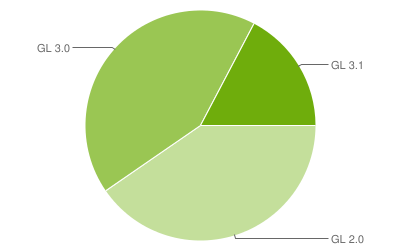 ( source of February 6, 2017 )
It is worth noting that the patented Microsoft approach allows using 4 channels to encode the color of the pixels in a cell. And it was from the very beginning that I became interested in drawing color vector images.
How to live on
The methods described above have the following disadvantages:
- The quality of the image with the method of triangulation in a mesh significantly depends on the number of triangles, which increases the allocated memory and the load on the video card (small but dense grids load the GPU more than the texture of the same size drawn on the quad).
- SDF as is does not imply the possibility of drawing multi-colored elements. One of the conditions is the "binary" of the original image.
- The methods of "random access" to the pixels defining various vector parameters require a lot of computational power on the GPU side, in particular, a lot of time is spent on additional texture reads.
Therefore, I had a desire to offer a slightly different way of drawing multicolored vector graphics, based on the same principle of the SDF.
Second Life for SDF
SDF has become synonymous with monochrome text character rendering. But if you imagine a vector image as a set of monochrome layers, then using the same SDF texture, you can draw a vector image of any complexity and color. That is, we simply divide the initial image into a set of monochrome layers.
An example - a box from Kenney's popular kit, cut into layers, looks like this:

This is the look of the SVG file. You may notice that the layers do not overlap, but "fit" together. When viewing such vector images through Inkscape, artifacts inherent in such a matching of these layers are clearly visible:

The presence of artifacts depends on how you create vector graphics, but for now let's take this option.
To action
For each layer, we will create our own SDF texture and set the layers on top of each other in the same order in which they appear in the SVG file.

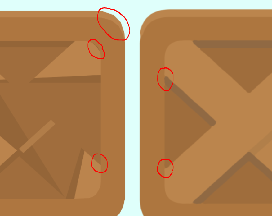
From left to right - SVG Importer with antialiasing enabled, “puffy” SDF, increased initial texture. SVG Importer was unable to parse the SVG from Inkscape normally, but that's not the point.
If you bring both objects very close, the differences look like this:
Triangulation:
- jagging is noticeable on the roundings, limited by the number of triangles (-)
- cracks may occur at joints for the same reason (-)
- sharp sharp corners (+)
- minimum overdraw (translucent geometry that overlaps each other) (+)
- total amount of triangles - 568
- allocated memory - 44 Kb
Puff SDF:
- a direct disadvantage of the classical approach is the loss of sharp corners (-)
- substantial overdraw (-)
- the total number of triangles is 26 (textures are drawn not on quads, but on automatically generated meshes encircling the texture in alpha. For a simpler version, you can simply multiply the number of layers by 2, that is, 10 triangles) (+)
- On a three-channel texture size of 256x128, compressed using ETC4. The layers are scattered across the channels, the layer size is 128x128, that is, three layers on the left side of the atlas in a separate channel and two layers on the right side of the atlas. Allocated memory - 16 KB (+)
The main disadvantage of this method compared with all the others is a substantial ovedraw. To draw this box you need 4 full-size layers placed on top of each other, plus a small quad for the fifth layer (a little dash). In the worst case, overdraw will be directly proportional to the number of layers of the vector image. The higher the resolution of the device, the slower the rendering will work.
But unlike most packages for parsing SVG files into meshes, pre-prepared textures take up much less space. Scaleform in this plan went further - they generated all the meshes on the fly while loading the scene, without clogging the application archive with previously created files. For comparison, the initial size of the box is 4 KB of text, that is, the mesh of the vector image previously collected with smoothing takes up 11 times more space than the raw text describing this vector shape.
Options - thousands of them
I also stumbled upon another way of converting a color image into an SDF view. [6] The bottom line is to use bit planes images for colors. Bit cards lay out the brightness of the color bit by bit.
That is, the bits of brightness are taken in order and put into a separate binary texture. Only one image channel needs 8 textures. That is, 24 textures per color image without transparency.
If you go further and present each such binary texture as an 8-bit SDF texture, then it turns out that for a full representation of the initial image you will need 24 eight-bit textures (and not 24 single-bit ones, which are obtained immediately after decomposition into bit-cards).
The process of restoring the initial color image from the bit-cards processed using the SDF is as follows:
- For each bitmap of each channel, the current SDF pixel value is checked.
- If it is less than 0.5, then the source bit is 1, if it is greater than 0. (0.5 in this case is an abstract value, the whole eight-bit numbers are compared with the value 127)
- All values of all bits are collected in order and each channel is restored separately. For example, if the current pixel of the red channel has the bit values equal to 01110011, then the red channel brightness is 115
- Passing through all channels of the current pixel in the same way.
- We restore the color value in three channels.
Although this algorithm is quite tricky, the quality leaves much to be desired:


Artifacts are caused by the fact that the problem of loss of accuracy when storing a reduced copy of an SDF texture is worsened by cutting color channels into a bitwise component. In my opinion, this method is not particularly applicable for this reason. But another drawback is the need to store 24 eight-bit SDF textures per source color image.
Results
I cannot offer a new full-fledged out-of-the-box solution, but there are ideas and attempts to make SDF encoding on palettes with contour markings, which may help to get rid of storing a large number of different textures for different channels and reduce overdraw.
The article has already turned out very large, and I had to significantly cut content. From what is not told:
- The easiest way to rasterize vector graphics without a headache and sleepless nights
The article above brought me to a friend of TheRabbitFlash , who shared a huge amount of information about rasterizing vector graphics in general and Flash in particular. "" Adobe Flash ( Adobe Animate), . - Scaleform Mobile SDK 5 Ants Starling, Tiny Thief, Flash + Starling.
- .
- ( Tiny Thief 2561).
Source: https://habr.com/ru/post/318880/
All Articles