First steps with STM32 and mikroC compiler for ARM architecture - Part 2, start ...
Having dealt with the basics and blinking the LED, you can proceed to the implementation of more complex tasks. Benefit microC compiler has many useful functions that greatly simplify the life of the programmer, especially a beginner.
In the last part, I told you how to implement a polling of the state of the MK port, for example, to poll the button connected to it. In general, the port in the STM32 MK is very complex. Here is the scheme of the GPIO port from the manual: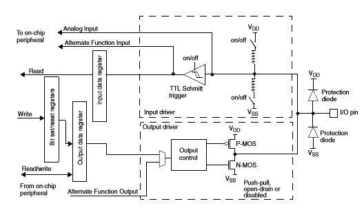
The port pin can work in several modes, directly as a digital port, besides many pins can be used as ADC inputs, PWM modulator outputs, external interrupt inputs, and hardware serial SPI and I2C interfaces. (for example, PA6 is the 6th port of A directly, 6th ADC input, 1 channel output of the 3rd PWM modulator / timer, and the MISO signal of the 1st SPI interface).
In microC for advanced GPIO configuration there is a function
GPIO_Set_Pin_Mode(&port_base, pin, config); - & port_base - a pointer to a GPIO port ( & GPIOE_BASE for port E or, for example, & GPIOA_BASE for port A );
- pin - port output with which we work ( _GPIO_PIN_5 for 5 pins or, for example, _GPIO_PIN_ALL for all pins of the port );
- config - port operation mode ( several parameters are written through the operator | );
- _GPIO_CFG_MODE_INPUT - Configured as an input;
- _GPIO_CFG_PULL_UP - Tightening resistor on + Vcc is turned on;
- _GPIO_CFG_PULL_DOWN - Tightening resistor is turned on for GND ;.
- _GPIO_CFG_PULL_NO - Tightening and tightening resistors are disconnected;
- _GPIO_CFG_MODE_ALT_FUNCTION - The output is used as input / output of the integrated peripheral module, for example, UART or SPI
- _GPIO_CFG_MODE_ANALOG - The output is used as an ADC input (in microcontrollers with a built-in DAC, as an output of a DAC);
- _GPIO_CFG_MODE_OUTPUT — Configured to exit;
- _GPIO_CFG_OTYPE_OD - Open drain mode is enabled;
- _GPIO_CFG_OTYPE_PP - The "push-pull" mode is enabled ("push-pull output", it is most often used);
- _GPIO_CFG_SPEED_MAX - GPIO, MAX operation speed for full-speed operation, which APB provides is permissible to use 400KHZ, 2MHZ, 10MHZ, 40MHZ, 50MHZ, 100MHZ.
- _GPIO_CFG_MODE_INPUT - Configured as an input;
In the last part, we configured the output port to the input command
GPIO_Digital_Input (&GPIOb_BASE, _GPIO_PINMASK_8); Otherwise it can be done:
GPIO_Set_Pin_Mode(&GPIOb_BASE, _GPIO_PINMASK_8, _GPIO_CFG_MODE_INPUT | _GPIO_CFG_PULL_NO); The same but turning on the power-up:
GPIO_Set_Pin_Mode(&GPIOb_BASE, _GPIO_PINMASK_8, _GPIO_CFG_MODE_INPUT | _GPIO_CFG_PULL_UP); By default, microC initializing the port to the input ( GPIO_Digital_Input () ) does not connect pull-up resistors to the MK pin, so if one is needed, then we use GPIO_Set_Pin_Mode () with additional parameters.
In the last part, I already told how to use the MC to interrogate the state of the input to which the button is connected. In real life, when using buttons, it is very desirable to introduce protection against the bounce of contacts (that this can be read on the vast expanses of the Network). In a nutshell, this is the output of a mechanical contact, instead of a single, burst of random pulses. MK can read them and process them incorrectly. There are both hardware ways to protect against chatter (for example, capacitance parallel to a button or Schmidt trigger) and enormous ones, of which a great many are described. microC to suppress contact bounce there is a special feature
Button(&port_base, pin, delay, state) We pass this function * port_base (for example & GPIOb_BASE); pin - pin number of the MK port; delay - time, pulses with duration less than which are considered bounce (for example, 1ms) and state - active state (the high or low level at the input of the port is controlled by the function).
Let's slightly change the program from the first part, by entering into it the protection from the chatter of the button:
void main() { GPIO_Digital_Output(&GPIOb_BASE, _GPIO_PINMASK_1); GPIO_Digital_Input(&GPIOb_BASE, _GPIO_PINMASK_8); // PB8 GPIOb_ODR.b1 = 0; while(1) { if (Button(&GPIOb_IDR, 8, 1, 1)) // PB(GPIOb), №8, 1 , ( ) - . 1 1 , - , { GPIOb_ODR.b1=~GPIOb_ODR.b1; Delay_ms(500); // 500 } else { GPIOb_ODR.b1 = 0; // , } } } When you press the button we see a flashing LED. Now we’ll do this so that the first time the LED starts blinking, and the next time it stops.
unsigned short state = 0; // , , 2 (2 - 1 - .) void main() { GPIO_Digital_Output(&GPIOb_BASE, _GPIO_PINMASK_1); GPIO_Digital_Input(&GPIOb_BASE, _GPIO_PINMASK_8); GPIOb_ODR.b1 = 0; while(1) { if (Button(&GPIOb_IDR, 8, 1, 1)) // state.b2=1; // if (state.b2 && Button(&GPIOb_IDR, 8, 1, 0)) // , , / { state.b2 = 0; // state.b1= ~state.b1; // } if (state.b1) // { GPIOb_ODR.b1=~GPIOb_ODR.b1; Delay_ms(250); } else { GPIOb_ODR.b1 = 0; } Delay_ms(1); } } Now, by pressing the button, the LED starts blinking, and by the next pressing it stops (should in any case) But this is not always the case ... The reason is that Delay_ms (250) is essentially 250 ms of the MK core busting through the empty cycle. At this time, he is only doing this and completely ignores any external influences on him (well, except for reset and power off, of course, a joke of humor :))
In order not to occupy precious microcontroller clock cycles by the formation of time intervals, there are special blocks in it, called timers. In STM32, their number reaches 14. They have slightly different settings and can be used not only to count the time intervals, but also for example to generate PWM. In fact, each timer is a TIMx_CNT register (for STM 32 they are 16 bit) which is incremented through a certain number of clock clock generator MK (More precisely, the APB1 bus ( for Timer1 timer - APB2 ) it is connected to). The number of APB clock cycles to increase the timer register value by 1 must pass, indicates the prescaler register, TIMx_PSC , by a 16-bit value in which the clock bus frequency is divided.
STM32F103 has 7 timers,
- TIM1 - Advanced-control timers , timers that allow advanced configuration of parameters (for example, the formation of pulses necessary for the operation of frequency converters used in the drive). In the future we will return to it in our articles. TIM1 has 4 PWM modulator channels;
- TIM2, TIM3, TIM4 - General-purpose timers - General-purpose timers . They are most often used, TIM2, TIM3, TIM4 have 4 channels of PWM modulator;
- WDT - Wachdog timer - Timer used to prevent the MK from hanging;
- SysTick timer is a 24-bit clock clock of the MK kernel, used, for example, to estimate the kernel load.
Many registers are used to set the timers (the parameters of the timers are also very much). We will refer to the parameters that we need when solving a particular task.
The main registers of each timer:
- TIMx_CNT - Actually counting register;
- TIMx_PSC - Frequency prescaler, the prescaler coefficient is TIMx_PSC + 1 (do not forget this, so as not to get into the situation: "how does it not work?" :));
- TIMx_ARR - The value of the counting register, when reached, the timer is reset and an interrupt is generated (see below);
- TIMx_CR1 - Timer parameter register;
- TIM_DIER - Register of the setting interrupted and DMA timer;
- TIMx_SR - Timer status register, for example, there is a flag in it indicating the operation of the interrupt.
When resetting the timer, if it is enabled by software, an interrupt is generated. An interrupt is a call to a specific portion of the program code for a certain event. Sources of interruptions can be built-in MK blocks, inputs having the function of creating an interrupt (int) as well as a DMA block. In fact, when an interrupt arrives, the MC goes from executing the main code to executing a specific subroutine, after which it returns to the main code (a special story occurs when another occurs during the processing of one interrupt, but we will not focus on this yet). In STM32 there are more than 70 so-called interrupt vectors - events triggering the execution of a subprogram - interrupt handler. By default, all interrupts are disabled. To enable interrupts from one block or another, it is necessary to change the configuration bits in the control registers of one block or another MC. In microC, to enable an interrupt, use the command
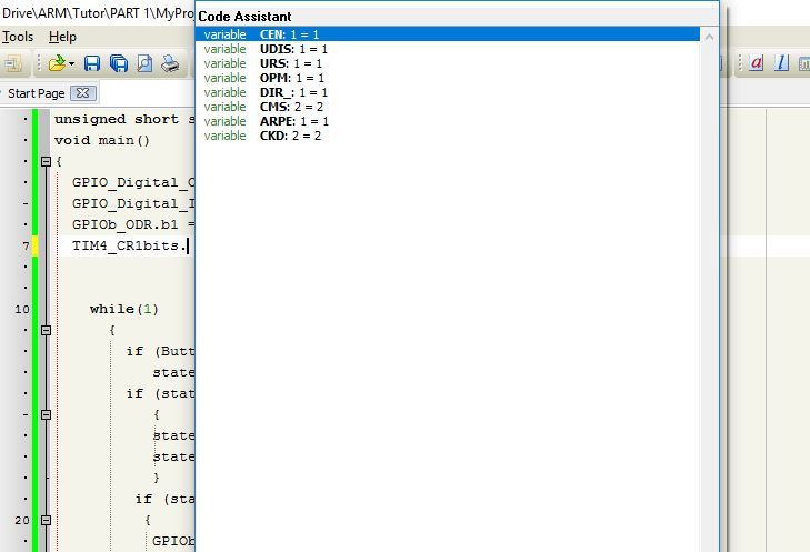
NVIC_IntEnable(NVIC_name) //NVIC_name - In general, microC has a very useful feature called "Code assistant" . It is called by pressing the key combination Ctrl + Spase . It is useful when you don’t remember the exact name of a parameter. Having typed the initial characters, the compiler will offer to complete the command itself, choosing from the possible values. For example, by typing "NVIC IntEnable (NVIC " b and calling "Code assistant" we have:

similar to the control register parameters. For example, typing " TIM4_CR1bits. ", We get:
Attentive readers noticed that to access a separate register bit, I used an expression like REGx.by , for example
GPIOb_ODR.b1=0; \\1 GPIOb_ODR TIM4_CR1.CEN \\ CEN TIM4_CR1 there is another form of recording the same action, and the "Code assistant" normally works only with it
GPIOb_ODRbits.ODR1=1; \\1 GPIOb_ODR TIM4_CR1bits.CEN \\ CEN TIM4_CR1 To configure our timer, you must perform the following steps
RCC_APB1ENR.TIM2EN = 1; // APB1 (1/2 , 72/2=36 ) 2, TIM2_CR1.CEN = 0; // 2, TIM2_PSC = 7199; // , 7199+1 = 7200, 72 10 K TIM2_ARR = 5000; // NVIC_IntEnable(IVT_INT_TIM2); // TIM2_DIER.UIE = 1; // TIM2_CR1.CEN = 1; // 2 * Important note. Although TIM2, TIM3, TIM4 are connected to the APB1 bus, which works, in our case, at half the frequency (APB1 has a maximum frequency of 36 MHz) HCLK, the timers when setting the APB1 divider other than 1 are clocked at twice the bus frequency, that is at a frequency of APB1 = HCLK / 2 TIMxCLK = APB1 x 2, in fact, in our case, the core frequency.
we set the timer to generate an interrupt every 500 ms.
Now we will create a function called when a timer interrupt arrives:
void Timer2_interrupt() iv IVT_INT_TIM2 { TIM2_SR.UIF = 0; // , !!! // } now everything is ready to blink once again with our LED, now with the help of a timer
unsigned short state = 0; void main() { GPIO_Digital_Output(&GPIOb_BASE, _GPIO_PINMASK_1); GPIO_Digital_Input(&GPIOb_BASE, _GPIO_PINMASK_8); RCC_APB1ENR.TIM2EN = 1; TIM2_CR1.CEN = 0; TIM2_PSC = 7199; TIM2_ARR = 5000; NVIC_IntEnable(IVT_INT_TIM2); TIM2_DIER.UIE = 1; TIM2_CR1.CEN = 1; while(1) { } } void Timer2_interrupt() iv IVT_INT_TIM2 { TIM2_SR.UIF = 0; GPIOb_ODR.b1=~GPIOb_ODR.b1; } Let's turn on and off the timer using our button, which will now work as it should.
unsigned short state = 0; void main() { GPIO_Digital_Output(&GPIOb_BASE, _GPIO_PINMASK_1); GPIO_Digital_Input(&GPIOb_BASE, _GPIO_PINMASK_8); RCC_APB1ENR.TIM2EN = 1; TIM2_CR1.CEN = 0; TIM2_PSC = 7199; TIM2_ARR = 5000; NVIC_IntEnable(IVT_INT_TIM2); TIM2_DIER.UIE = 1; while(1) { if (Button(&GPIOb_IDR, 8, 1, 1)) state.b2=1; if (state.b2 && Button(&GPIOb_IDR, 8, 1, 0)) { state.b2 = 0; state.b1= ~state.b1; } if (state.b1) { TIM2_CR1.CEN = 1; // } else { TIM2_CR1.CEN = 0; // GPIOb_ODR.b1 = 0; // } Delay_ms(1); } } void Timer2_interrupt() iv IVT_INT_TIM2 { TIM2_SR.UIF = 0; GPIOb_ODR.b1=~GPIOb_ODR.b1; } * to be continued
')
Source: https://habr.com/ru/post/318352/
All Articles