Lecture by Charles Moore, creator of Forth: 144-core processor, why? Is it difficult to program 144 cores?
The creator of the 144-core GA144 processor and the Forth programming language, the well-known programmer Charles Moore (Charles H. Moore), also known as Chuck Moore, in his lecture talks about the prospects of using the 144-core asynchronous chip created by his company , GreenArrays, as well as its programming. After all, its chip consumes only 7 pJ of energy (when performing the basic ALU instruction, which takes 1.5 nanoseconds), which makes it indispensable in cases when the processor can be powered only from an independent source of energy without the possibility of recharging, ranging from developments in medicine and ending with robotics. Unused cores consume only 100 NW, while the active one requires only 4 milliwatts when processing 666 MIPS: a dense code minimizes the number of instructions to be executed, reducing the number of instruction samples, switching transistors and the duty cycle.
Since the lecture has not been published yet, we published it for you on youtube:
')
If someone will be able to make subtitles - write, add, we will be very grateful if someone finds time to do such important work.
The processor itself went on sale in 2011, at a price of $ 20 . In this publication, we tried to systematize the available information and fill in the gaps that may arise after reading the documentation from GreenArrays.
If you need effective power management and high speed, the ability to create parallel energy-efficient applications for a wide range of tasks - the multi-core GA144 processor can provide you with this. GA144 is an interesting tool for analyzing and modeling parallel data processing algorithms that are intended for use in homogeneous computing environments.
Here are some reasons to consider it as such:
- it has 144, 18-bit kernels;
- it is characterized by completely independent asynchronous cores, therefore it does not have a clock;
- it is programmed in Forth and GreenArrays, which in turn provide colorForth, the version of arrayForth specifically for GA144;
- its hardware capabilities for synchronizing tasks on different kernels and high speed of code execution;
- the ability to programmatically set the functionality of I / O lines.
But, despite the fact that there is a lot of relevant documentation on the programming of this chip, for some, getting started with it causes difficulties. Online tutorials usually work for the old version of arrayForth and are not supported by new ones. Basic information is distributed across all available documentation. And if there is a desire to begin to work professionally with GA144, then you will have to carefully go through it all. Think well before you start your experiments with him, there will be no quick result. Especially if you need to program a chip with an IDE that looks like this:
But do not worry, I will try to explain in this post how to write an example of the “Hello World” standard and run it on the simulator, without really going into the details of the chip operation. Most likely you already have some idea of GA144, Forth and its stack. In addition, I recommend that you read the instructions in arrayForth to get a basic idea of what it is.
If you did everything right and started arrayForth, you should see a similar window:
You should know that it uses a special keyboard layout to enter various types and colors of syntax (hence colorForth). On page 13, chapter 3 of the arrayForth user manual, you can find the layout used in the editor. Before we start writing our “Hello World” example, we need to know how the memory is organized, where we leave our code, which nodes which code block is executed, etc.
The memory in arrayForth is organized into 1400 blocks, some of them contain the software of the system itself, such as a compiler and a simulator, others contain code written by the user or simply empty. A summary of how the memory blocks are organized can be found on page 18, chapter 4 of the arrayForth user manual, and a detailed description can be found in the file EVB001-02b.html, which is located in the installation folder.
You can see that blocks from 840 to 1078 can be used to store user code. Please note that even-numbered blocks may contain custom code, and odd-numbered blocks are used to store user comments.
The GA144 chip consists of 144 F18 nodes in an 18 × 8 grid:
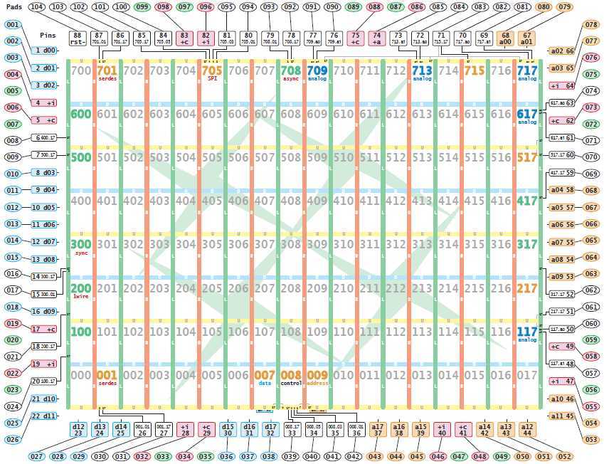
Each node has an identifier that begins with 000 on the lower left node and ends 717 for the upper right node. Each node is associated with neighboring nodes. Extreme nodes have access to the outside, either directly or through peripheral devices such as UART, SPI, ADC, etc. Therefore, you must carefully plan the location of your application.
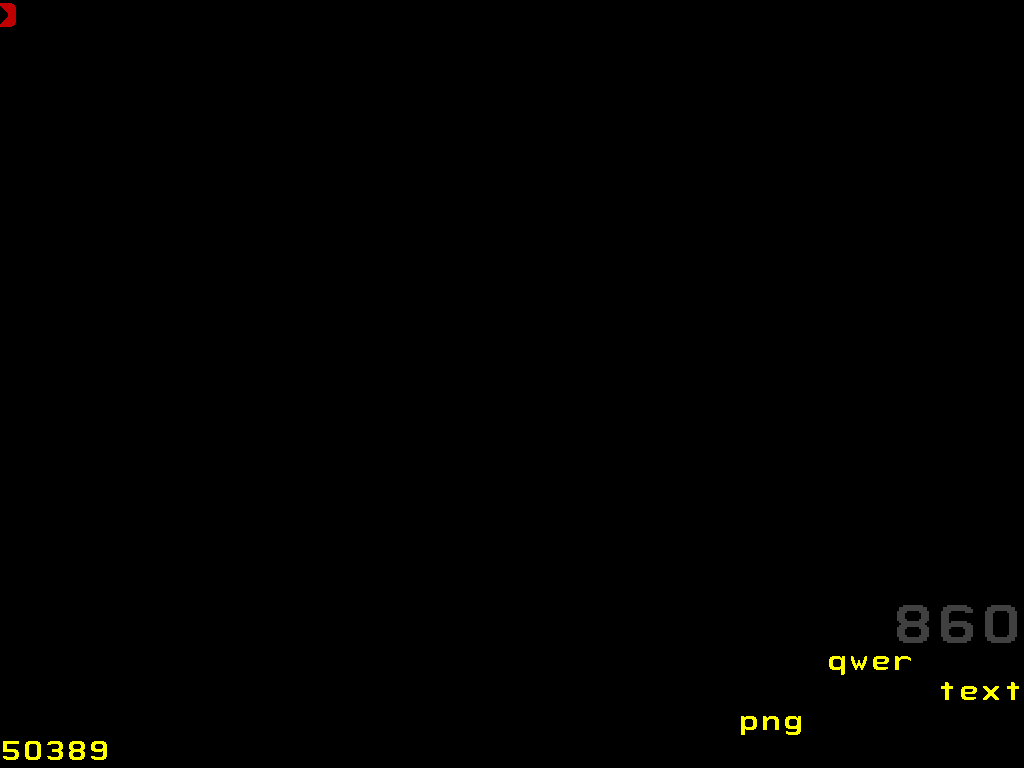
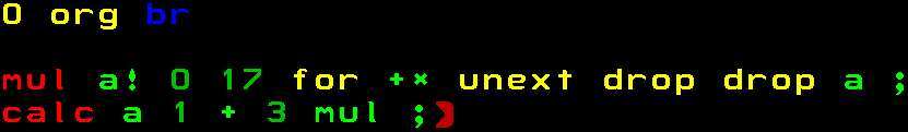
Now that we know a little about GA144, let's write our first piece of code that performs the following calculations: 3 (x + 1). We will place our code in block 860, which is accessible to custom code.
860 <space> edit <space>
This command opens the editor and displays us an empty block:
Enter the following command:
On the monitor you should see a similar picture:

If you know the assembler, then you should understand that the yellow part 0 org means that everything that will be entered further will be placed in the memory cell from 0 and above. Blue br is an editor command that does not compile into the executable code, but rather tells the editor to add two new lines. If it were cr, then only one new line would be added.
Next, we define three words (functions): setup, calc, and mul.
setup - will give the value of the variable x in our formula 3 (x + 1) and save it in the register.
calc will extract the value in register a, add to it, and multiply it by three.
Mul is a function that performs 18-bit multiplication, since the F18 node does not have a single multiplication command.
Let's first compile the code for the mul function:

Next comes the calc function:
The final setup function:
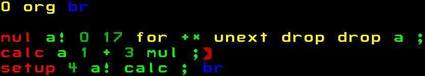
In this case, we have chosen x = 4, which will result in 3 (4 + 1) = 15 = 0x0F in hexadecimal. We are almost done! The last part of our “Hello World” example is to make sure that the entry point of our program (setup) is called when the node is loaded with our code. We can install it like this:
This gives us the last line of our code, and places the entry point to our code at 0xA9, where the installation will be called.
Now press the spacebar to exit edit mode (you will see that at the bottom of the red 860 from the right side will turn gray). We need to compile the code, this can be done by typing compile and pressing the spacebar. You can also save the state of all 1400 blocks using the save function (save type and space).
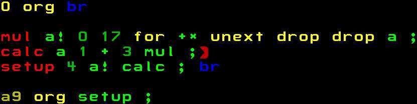
So we wrote the code, but how do we put it in one of the nodes? This is the part that is not affected if you view older documentation. Block 200 contains instructions for downloading code from blocks to nodes. This is exactly the place where we can download our code. First you need to change all the instructions that are not white or blue to white. You can do this by placing the cursor on the instruction / number and clicking until it turns pale. :)
We will place the boot instructions after the first line.
<u *> 400 <space> node <space> 860 <space> load <space> <esc *> <x *> br <space> <esc *>
This line selects node 404 and loads block 860 into it. It looks something like this:
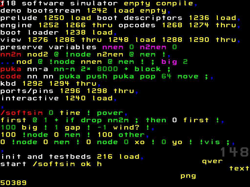
The reason we put all this in block 200 is because the softsim simulator, which is in arrayForth (blocks 148-150), initially sets up the simulator (block 148) and the application download code is stored in block 200 (block 150).
You can repeat this step if you want to place the same block in another node (the same code runs in parallel), or if you want to load another block of code in another node. If we started the simulator now, we would see that node 404 does not execute any code. In order to make sure that the node will start the program counter, which indicates the correct entry point, we need to change block 216. This block contains the configuration and testsbeds for the simulator.
Open block 216:
And add the following code before the line that starts with the comment “rom write test 200 + node 13 / p,”:
Block 216 now looks like this:
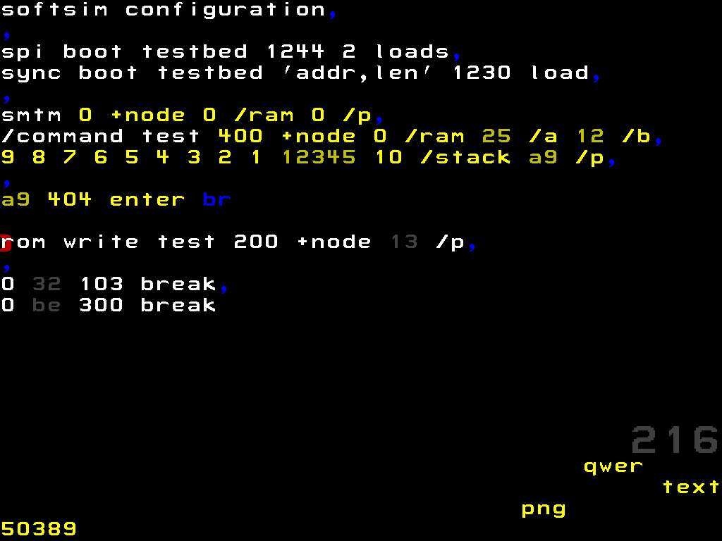
Now the correct entry point for node 404 has been set, we are ready to run our code in the simulator!
Type softsim and press the spacebar to start the simulator.
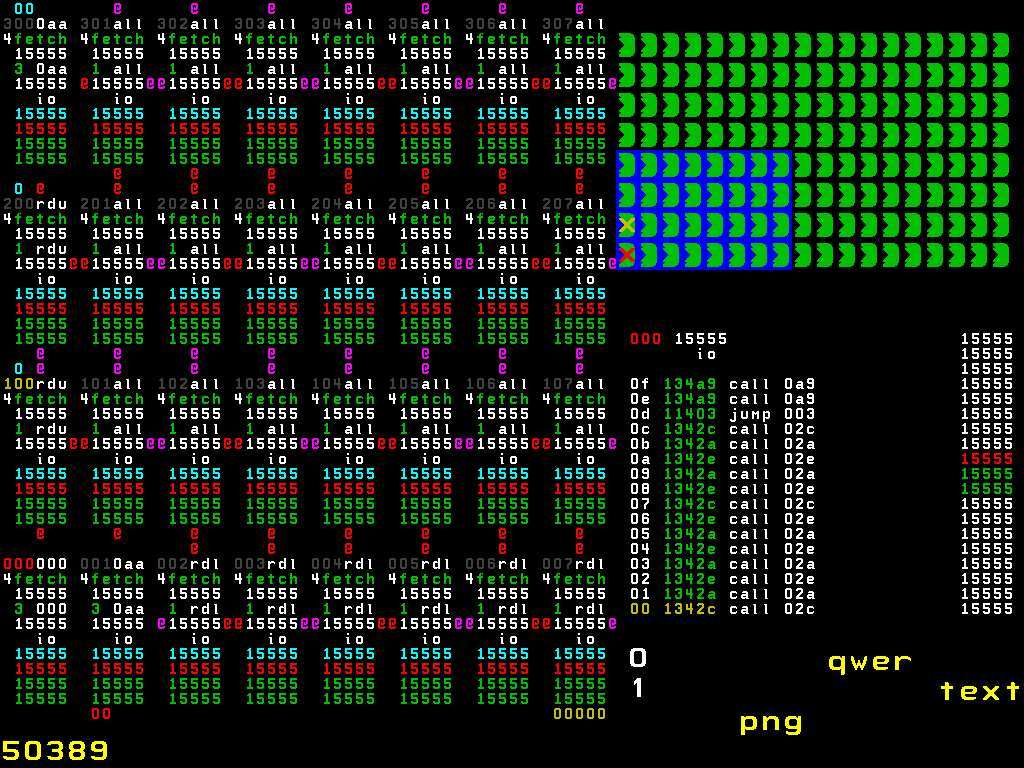
Page 33, chapter 7 of the instructions in arrayForth describes how the simulator works, but I will try to explain briefly.
In the upper right corner, there is a 18 by 8 grid representing all the nodes of GA144. A green symbol means a node that is running, gray means that the node is suspended. If it were not for the modified block 216, as described above, node 404 (5th from the left and 4 above) would be gray, since our Hello World example would not work. There are also red and yellow X, which represent the “focus” node and the “other” node, respectively. The bottom right corner shows the contents of the focal node memory. If you press the "/" key, then in the upper right corner will be replaced by the contents of the memory of the "other" node. This is useful if you have two nodes interacting with each other. The left part of the screen displays the internal state of the nodes, the contents of the registers. The selected grid 8 by 4 nodes is marked with a blue rectangle in the grid overview in the upper right corner, it can be moved to select the nodes whose internal state we want to know:
Top down:
If you put a red X on node 404, and also set up a blue rectangle to include node 404, we can see what happens to the node on which we want to run our example:
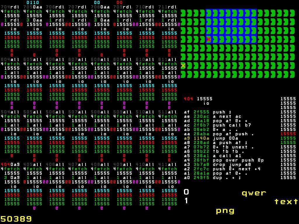
By pressing n several times, we can see that node 404 executes our code:
The following is a brief explanation of what happens in chronological order. First, the memory address is indicated, and a numbered list of instructions is shown next to it, which correspond to the command slots (see F18 Technology document for more detailed and extensive additional information).
0xA9
0xA
0xC
0x6
0x9
0x0
0x3
0x4
0x5
When the last instruction is executed, we can see 0xF or 15 in decimal on the top of the stack, which confirms that our example works correctly! I hope this post will help fill in the gaps after reading the GreenArrays documentation.
The article was published with the assistance of ua-hosting.company hosting provider. Therefore, taking this opportunity, we want to remind you about the action:
VPS (KVM) with dedicated drives (full-fledged analog of dedicated entry-level servers from $ 29) in the Netherlands and the USA free for 1-3 months for all + 1 month bonus for geektimes
Do not forget that your orders and support (cooperation with you) will allow you to publish in the future even more interesting material. We would appreciate your feedback and criticism and possible orders. ua-hosting.company - happy to make you happier.
Since the lecture has not been published yet, we published it for you on youtube:
')
If someone will be able to make subtitles - write, add, we will be very grateful if someone finds time to do such important work.
The processor itself went on sale in 2011, at a price of $ 20 . In this publication, we tried to systematize the available information and fill in the gaps that may arise after reading the documentation from GreenArrays.
144-core processor, why?
If you need effective power management and high speed, the ability to create parallel energy-efficient applications for a wide range of tasks - the multi-core GA144 processor can provide you with this. GA144 is an interesting tool for analyzing and modeling parallel data processing algorithms that are intended for use in homogeneous computing environments.
What makes the GreenArrays GA144 chip unique?
Here are some reasons to consider it as such:
- it has 144, 18-bit kernels;
- it is characterized by completely independent asynchronous cores, therefore it does not have a clock;
- it is programmed in Forth and GreenArrays, which in turn provide colorForth, the version of arrayForth specifically for GA144;
- its hardware capabilities for synchronizing tasks on different kernels and high speed of code execution;
- the ability to programmatically set the functionality of I / O lines.
But, despite the fact that there is a lot of relevant documentation on the programming of this chip, for some, getting started with it causes difficulties. Online tutorials usually work for the old version of arrayForth and are not supported by new ones. Basic information is distributed across all available documentation. And if there is a desire to begin to work professionally with GA144, then you will have to carefully go through it all. Think well before you start your experiments with him, there will be no quick result. Especially if you need to program a chip with an IDE that looks like this:
But do not worry, I will try to explain in this post how to write an example of the “Hello World” standard and run it on the simulator, without really going into the details of the chip operation. Most likely you already have some idea of GA144, Forth and its stack. In addition, I recommend that you read the instructions in arrayForth to get a basic idea of what it is.
First start
If you did everything right and started arrayForth, you should see a similar window:
You should know that it uses a special keyboard layout to enter various types and colors of syntax (hence colorForth). On page 13, chapter 3 of the arrayForth user manual, you can find the layout used in the editor. Before we start writing our “Hello World” example, we need to know how the memory is organized, where we leave our code, which nodes which code block is executed, etc.
Memory organization
The memory in arrayForth is organized into 1400 blocks, some of them contain the software of the system itself, such as a compiler and a simulator, others contain code written by the user or simply empty. A summary of how the memory blocks are organized can be found on page 18, chapter 4 of the arrayForth user manual, and a detailed description can be found in the file EVB001-02b.html, which is located in the installation folder.
You can see that blocks from 840 to 1078 can be used to store user code. Please note that even-numbered blocks may contain custom code, and odd-numbered blocks are used to store user comments.
Knot Layout
The GA144 chip consists of 144 F18 nodes in an 18 × 8 grid:
Each node has an identifier that begins with 000 on the lower left node and ends 717 for the upper right node. Each node is associated with neighboring nodes. Extreme nodes have access to the outside, either directly or through peripheral devices such as UART, SPI, ADC, etc. Therefore, you must carefully plan the location of your application.
"Hello World"
Now that we know a little about GA144, let's write our first piece of code that performs the following calculations: 3 (x + 1). We will place our code in block 860, which is accessible to custom code.
860 <space> edit <space>
This command opens the editor and displays us an empty block:
Enter the following command:
<u*>0<>org<><esc*><x*>br<><esc*>On the monitor you should see a similar picture:
If you know the assembler, then you should understand that the yellow part 0 org means that everything that will be entered further will be placed in the memory cell from 0 and above. Blue br is an editor command that does not compile into the executable code, but rather tells the editor to add two new lines. If it were cr, then only one new line would be added.
Next, we define three words (functions): setup, calc, and mul.
setup - will give the value of the variable x in our formula 3 (x + 1) and save it in the register.
calc will extract the value in register a, add to it, and multiply it by three.
Mul is a function that performs 18-bit multiplication, since the F18 node does not have a single multiplication command.
Let's first compile the code for the mul function:
<i*>mul<>a!<>0<>17<><esc*><u*>for<><esc*><o*>+*<><esc*><u*>unext<>drop<>drop<><esc*><o*>a<>;<><esc*>Next comes the calc function:
<i*>calc<>a<>1<>+<>3<>mul<>;<><esc*>The final setup function:
<i*>setup<>4<>a!<>calc<>;<><esc*><x*>br<><esc*>In this case, we have chosen x = 4, which will result in 3 (4 + 1) = 15 = 0x0F in hexadecimal. We are almost done! The last part of our “Hello World” example is to make sure that the entry point of our program (setup) is called when the node is loaded with our code. We can install it like this:
<u*><F1*>0a9<><F1*>org<><esc*><o*>setup<>;<><esc*>This gives us the last line of our code, and places the entry point to our code at 0xA9, where the installation will be called.
Now press the spacebar to exit edit mode (you will see that at the bottom of the red 860 from the right side will turn gray). We need to compile the code, this can be done by typing compile and pressing the spacebar. You can also save the state of all 1400 blocks using the save function (save type and space).
Node configuration
So we wrote the code, but how do we put it in one of the nodes? This is the part that is not affected if you view older documentation. Block 200 contains instructions for downloading code from blocks to nodes. This is exactly the place where we can download our code. First you need to change all the instructions that are not white or blue to white. You can do this by placing the cursor on the instruction / number and clicking until it turns pale. :)
We will place the boot instructions after the first line.
<u *> 400 <space> node <space> 860 <space> load <space> <esc *> <x *> br <space> <esc *>
This line selects node 404 and loads block 860 into it. It looks something like this:
The reason we put all this in block 200 is because the softsim simulator, which is in arrayForth (blocks 148-150), initially sets up the simulator (block 148) and the application download code is stored in block 200 (block 150).
You can repeat this step if you want to place the same block in another node (the same code runs in parallel), or if you want to load another block of code in another node. If we started the simulator now, we would see that node 404 does not execute any code. In order to make sure that the node will start the program counter, which indicates the correct entry point, we need to change block 216. This block contains the configuration and testsbeds for the simulator.
Open block 216:
216<>edit<>And add the following code before the line that starts with the comment “rom write test 200 + node 13 / p,”:
<u*><F1*>0a9<><F1*>404<>enter<><esc*><x*>br<><esc*>Block 216 now looks like this:
Now the correct entry point for node 404 has been set, we are ready to run our code in the simulator!
Running the simulator
Type softsim and press the spacebar to start the simulator.
Page 33, chapter 7 of the instructions in arrayForth describes how the simulator works, but I will try to explain briefly.
In the upper right corner, there is a 18 by 8 grid representing all the nodes of GA144. A green symbol means a node that is running, gray means that the node is suspended. If it were not for the modified block 216, as described above, node 404 (5th from the left and 4 above) would be gray, since our Hello World example would not work. There are also red and yellow X, which represent the “focus” node and the “other” node, respectively. The bottom right corner shows the contents of the focal node memory. If you press the "/" key, then in the upper right corner will be replaced by the contents of the memory of the "other" node. This is useful if you have two nodes interacting with each other. The left part of the screen displays the internal state of the nodes, the contents of the registers. The selected grid 8 by 4 nodes is marked with a blue rectangle in the grid overview in the upper right corner, it can be moved to select the nodes whose internal state we want to know:
Top down:
- Node number (gray), COM port address (white)
- Slot number (white), opcode name (green)
- Command register (white)
- Memory timer (green), program counter (white)
- A, register (white)
- B, B register (white)
- IO, IO register (turquoise)
- R, top of the return stack (red)
- T, top of data stack (green)
- S, data stack (green)
- @ Represents the communication port that is used.
Run our code
If you put a red X on node 404, and also set up a blue rectangle to include node 404, we can see what happens to the node on which we want to run our example:
By pressing n several times, we can see that node 404 executes our code:
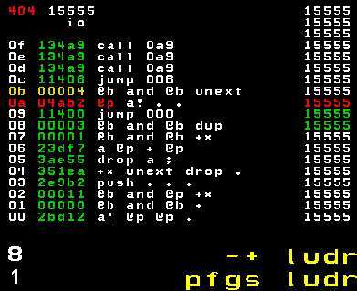
The following is a brief explanation of what happens in chronological order. First, the memory address is indicated, and a numbered list of instructions is shown next to it, which correspond to the command slots (see F18 Technology document for more detailed and extensive additional information).
0xA9
- Go to 0xA.
0xA
- Put the value stored in 0xB (which is 4) on the stack.
- Store at the top of the stack in register A.
- Nop.
- Nop.
0xC
- Go to 0x6.
0x6
- Put the value stored in register A on the stack.
- Put the value stored in 0x7 (1) on the stack.
- Perform addition.
- Put the value stored in 0x8 (3) on the stack.
0x9
- Go to 0x0.
0x0
- Store at the top of the stack in register A.
- Put the value stored in 0x1 (0) on the stack.
- Put the value stored in 0x2 (0x11 = 17) on the stack.
- Nop.
0x3
- Store at the top of the stack at the top of the return stack.
- Nop.
- Nop.
- Nop.
0x4
- Perform step multiplication.
- Go to the next instruction if the return stack is 0, otherwise return to the previous slot.
- Drop the value stored at the top of the data stack.
- Nop.
0x5
- Drop the value stored on top of the data stack.
- Put the value stored in register A on the stack.
- Return.
When the last instruction is executed, we can see 0xF or 15 in decimal on the top of the stack, which confirms that our example works correctly! I hope this post will help fill in the gaps after reading the GreenArrays documentation.
The article was published with the assistance of ua-hosting.company hosting provider. Therefore, taking this opportunity, we want to remind you about the action:
VPS (KVM) with dedicated drives (full-fledged analog of dedicated entry-level servers from $ 29) in the Netherlands and the USA free for 1-3 months for all + 1 month bonus for geektimes
Do not forget that your orders and support (cooperation with you) will allow you to publish in the future even more interesting material. We would appreciate your feedback and criticism and possible orders. ua-hosting.company - happy to make you happier.
Source: https://habr.com/ru/post/318144/
All Articles