Huawei router + hypervisor in one package. Starting from scratch
This article will be useful to system administrators who plan to work with Huawei network equipment, as well as IT professionals who are faced with the task of developing their own solutions based on standard platforms. It will provide a detailed description of device configuration via the command line (CLI).
I received for testing and studying the product of Huawei Enterprise - Huawei AR169W-P-M9. As follows from the description on the manufacturer’s website, this device combines a full range of services, including routing, switching, security, and wireless access, and also contains an open service platform (OSP, which is essentially an x86 computer) that can provide virtually any functionality available on the x86 platform.
If you simplify everything, then this is a full-fledged enterprise-level router with an integrated hypervisor based on x86 architecture, and all this is the size of a thick book. Consider the device closer. The main characteristics of the manufacturer's website below.
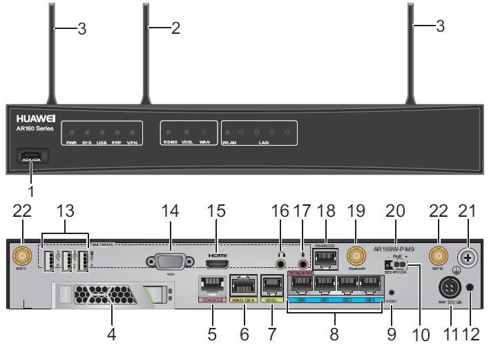
Pic1
| 1 - USB port (host) | 2 - Bluetooth antenna |
| 3 - Two Wi-Fi antennas | 4 - Slot for additional. Hard Drive (HDD 2.5 ”) |
| 5 - Console port | 6 - WAN 1GE Ethernet Port |
| 7 - WAN VDSL Port | 8 - LAN - 4-port switch GE thernet |
| 9 - Reset Reset Button | 10 - Connector for PoE power supply ports (100 W). Not included. |
| 11 - Connector for a standard power supply (60 W) | 12 - Connector for fixing the power cable. |
| 13 - Three USB interfaces (host). Output power of each 5 W. | 14 - VGA to connect the monitor. |
| 15 - HDMI video interface | 16 - Headphone Jack |
| 17 - microphone jack | 18 - RS485 / 232 interface |
| 19 - Interface for connecting a Bluetooth antenna | 20 - The name of the model. |
| 21 - Grounding Connector | 22 - Two Wi-Fi antennas |
Data sheet
| Core processor | Dual-core, 1 GHz |
| Main memory | 512 MB |
| OSP system memory | 8 GB |
| Flash main device | 512 MB |
| Hard disk HDD OSP system (build in) | 64 GB |
| OSP system processor | Intel Atom 1.9 GHz 4 Core |
| Dimensions (H x W x D) | 44.5 mm x 300 mm x 220 mm |
| Wi-Fi | 802.11b / g / n + 802.11ac |
| Service Forwarding Performance (IMIX) | 150 MB / s |
| Weight | 2.8 kg. |
| Nutrition | 100V - 240V |
Router Features
| Basic functionality | ARP, DHCP, NAT, and Sub interface management |
| WLAN (AP - FAT Access Point) | AP management, WLAN QoS, WLAN security, WLAN radio management, and WLAN user management (WLAN models support WLAN AP features) |
| WLAN (AC - Access Point Controller) | AP management (AC discovery / AP access / AP management), CAPWAP, WLAN user management, WLAN radio management (802.11a / b / g / n), WLAN QoS (WMM), and WLAN security (WEP / WPA / WPA2 / Key management) |
| LAN | IEEE 802.1P, IEEE 802.1Q, IEEE 802.3, VLAN management, MAC address management, MSTP, etc. |
| Ipv4 unicast routing | Routing policy, static route, RIP, OSPF, IS-IS, and BGP |
| Ipv6 unicast routing | Routing policy, static route, RIPng, OSPFv3, IS-Isv6, and BGP4 + |
| Multicast | IGMP v1 / v2 / v3, PIM SM, PIM DM, and MSDP |
| VPN | IPSec VPN, GRE VPN, DSVPN, L2TP VPN, and Smart VPN |
| QoS | Diffserv mode, Priority mapping, traffic policing (CAR), traffic shaping, congestion avoidance (based on IP precedence / DSCP WRED), congestion management (LAN interface: SP / WRR / SP + WRR; WAN interface: PQ / CBWFQ), MQC (traffic classification, traffic behavior, and traffic policy), Hierarchical QoS, and Smart Application Control (SAC) |
| Security | ACL, firewall, 802.1x authentication, AAA authentication, RADIUS authentication, HWTACACS authentication, broadcast storm suppression, ARP security, ICMP attack defense, URPF, CPCAR, blacklist, IP source tracing, and PKI |
| Management and Maintenance | Upgrade management, device management, web-based GUI, GTL, SNMP v1 / v2c / v3, RMON, NTP, CWMP, Auto-Config, site deployment using USB disk, and CLI |
The following operating systems can be installed on the OSP service module:
• Windows Server 2003 32bit,
• Windows Server 2008 R1 32bit,
• Windows Server 2008 R2 64bit,
• Windows 7 32bit sp1,
• Windows 8.x
• Red Hat Enterprise 6.5,
• Red Hat Enterprise 7.0,
• SUSE Enterprise 11 SP1,
• Fedora Core 20,
• Debian Wheezy.
After a more detailed study of the device, I sketched the following block diagram of the device:
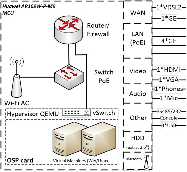
Pic2
As you can see, the device conventionally consists of two parts:
The MCU is the main device that is the Huawei AR Series router. And as a matter of fact it is no different from it, all the functionality of routers of this series is available in this device.
OSP - open system platform - is essentially an x86 computer on which the QEMU hypervisor is installed. It communicates with the MCU through a virtual switch (vSwitch). In the MCU command line, we will see the device as a separate interface (I tried to reflect this on the structural diagram as a separate link to the logical router). Management of the hypervisor also comes from the command line of the router, which in my opinion is not very convenient, perhaps in the future this will change and it will be possible to configure OSP via the keyboard and monitor or via the WEB interface.
Wi-Fi module (802.11b / g / n + 802.11ac)
- All possible ports for interacting with the outside world (described above).
In my practice, I often deal with Huawei network equipment, I think that I know its architecture, the VRP operating system and CLI quite well. But when I found out about the existence of such a “hybrid”, it became interesting to me - at what level does x86 and VRP integrate in it? What will the hypervisor look like in terms of the router? And what will the network resources of the router look like in terms of the x86 operating system installed on the service platform? And interest, first of all, is connected with the opening options for solving various typical tasks - after all, in fact, almost everything is already in one box, for example, here are the use cases:
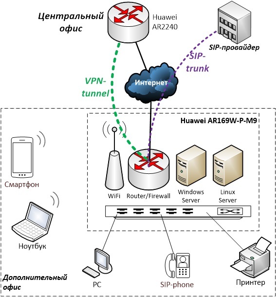
Fig. 3
Figure 3 shows the basic scheme for connecting an additional office to the main one. A device in an additional office solves the problem of accessing the Internet, distributing Wi-Fi, providing IP telephony, switching four devices, and up to two servers for tasks that need to be solved locally.
The second option:
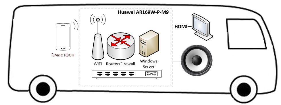
Fig. four
Solution for public transport. The device will distribute the Internet to passengers, which it will receive via 3G / 4G, as well as broadcast advertising through the HDMI interface and the monitor and column connected to it. Or, for example, determining the location by GPS, conduct a tour for passengers. To do this, of course, the corresponding application must be running on the guest OS. It is also worth noting that for this application it is more appropriate to use the industrial version of the AR 500 series, which is made in a special case that protects the device from shaking.
I think that you can come up with many uses, these are the first options that came to my mind.
Initial settings of the router.
The default password for the console (console parameters are standard, as in Cisco: 9600baud, without parity):
Username: admin
Password: Admin @ huawei
(In some early versions of VRP, the password may be Admin @ 123, but in newer versions, such as above).
1) We set the IP address for VlanInterface1, in which by default are the ports of the LAN switch GE0-GE4, as well as the default route:
<Huawei>system-view Enter system view, return user view with Ctrl+Z. [Huawei]sysname AR169 [AR169]interface Vlanif1 [AR169-Vlanif1]ip address 172.31.31.77 255.255.255.0 [AR169-Vlanif1]quit [AR169]ip route-static 0.0.0.0 0.0.0.0 172.31.31.1 2) We configure SSH access to the device, having previously created the user and generated the rsa keys:
[AR169]rsa local-key-pair create The key name will be: Host RSA keys defined for Host already exist. Confirm to replace them? (y/n):y The range of public key size is (512 ~ 2048). NOTES: If the key modulus is less than 2048, It will introduce potential security risks. Input the bits in the modulus[default = 2048]: Generating keys... ...........................................................................................................................................+++ ....................+++ ..............................................++++++++ ................++++++++ [AR169]user-interface vty 0 4 [AR169-ui-vty0-4]authentication-mode aaa [AR169-ui-vty0-4]protocol inbound ssh [AR169-ui-vty0-4]quit [AR169]aaa [AR169-aaa]local-user user1 password irreversible-cipher Pa$$w0rd [AR169-aaa]local-user user1 privilege level 15 [AR169-aaa]local-user user1 service-type ssh http terminal [AR169]ssh user user1 authentication-type password 3) Next, the optional item is the software update to the latest version. Before you start working with any device, it is highly recommended that you upgrade to the latest software version.
Check which version of the VRP software is currently on the router:
[AR169]display version Huawei Versatile Routing Platform Software VRP (R) software, Version 5.160 (AR160 V200R007C00SPC600PWE) Copyright (C) 2011-2016 HUAWEI TECH CO., LTD Huawei AR169W-P-M9 Router uptime is 0 week, 0 day, 0 hour, 53 minutes MPU 0(Master) : uptime is 0 week, 0 day, 0 hour, 53 minutes SDRAM Memory Size : 512 M bytes Flash 0 Memory Size : 512 M bytes MPU version information : 1. PCB Version : ARSRU169AGW-L VER.D 2. MAB Version : 0 3. Board Type : AR169W-P-M9 4. CPLD0 Version : 0 5. BootROM Version : 1 SubBoard[1]: 1. PCB Version : AR-1OSPBT-D VER.B 2. Board Type : OSP-X86 As you can see, the VRP software version of this router is V200R007C00SPC600PWE. You can conditionally decrypt as version 200, release 007, release number 00, service pack 600. The letters PWE mean Payload without encryption, which means that strong encryption with a long key above 56 bits is disabled in this software version. If these letters are not in the software name, then the device will support strong encryption.
At the time of this writing, the latest available version is V200R007C00SPC900, it can be found on the manufacturer’s website by searching for the keywords “AR 169 OSP”:
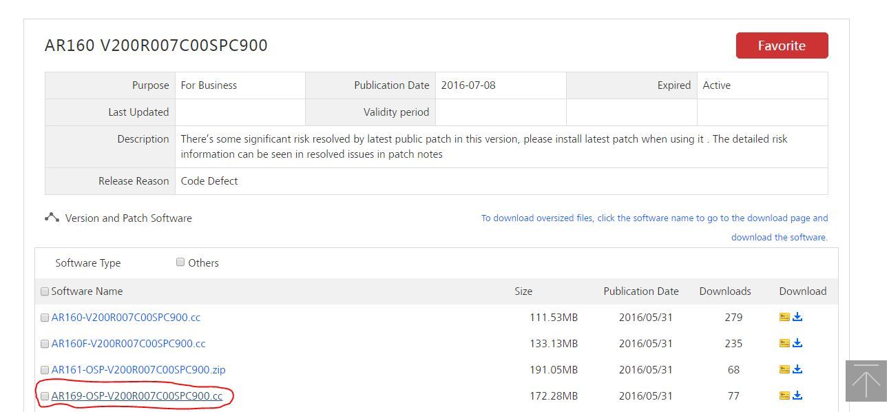
If the file will not be available for download (icon in the form of a lock near the file name), then you should contact your partner through whom the equipment was purchased.
Download the file with AR169-OSP-V200R007C00SPC900.cc and upload it to the TFTP server. I use for this purpose free tftpd64 for Windows. My tftp server is located on the same network as VLAN1 on the router. The address of the tftp server is 172.31.31.250.
Next, to download the file, you need to go into user mode (with triangular brackets) and give the command to download the file from the server tftp:
<AR169>tftp 172.31.31.250 get AR169-OSP-V200R007C00SPC900.cc The download of the file to the built-in flash-memory should begin. After downloading, from the same mode, check the contents of the flash command dir and make sure that everything is downloaded.
Further, so that the next time the device is rebooted, a new version of the software is loaded, in the same user mode you need to give a command with an explicit indication of this new file:
<AR169>startup system-software flash:/AR169-OSP-V200R007C00SPC900.cc Next, after rebooting, we’ll make sure that the router has booted with the new V200R007C00SPC900 firmware version.
4) We proceed to the creation of a virtual machine.
A virtual machine is created in the CLI interface of the router in virtual-environment mode.
First we will check if DHCP is enabled on the virtual interfaces GE0 / 0/5 and GE0 / 0/6 that connect the router and the OSP card.
To do this, look at the configuration of the entire device:
[AR169]display current-configuration … interface GigabitEthernet0/0/5 ip address 192.168.2.1 255.255.255.0 dhcp select interface # interface GigabitEthernet0/0/6 description VirtualPort ip address 192.168.3.1 255.255.255.0 dhcp select interface # I cut the extra output, leaving only the output of the fifth and sixth interfaces. As you can see, there is an enabled DHCP server here that will distribute IP addresses from the / 24 grids to these interfaces.
In my case, this was configured by default, but if DHCP is not configured on these interfaces (at least it is written about this in the manual), you should enable it:
[AR169]dhcp enable [AR169]interface GigabitEthernet0/0/5 [AR169-GigabitEthernet0/0/5]dhcp select interface [AR169-GigabitEthernet0/0/5]quit [AR169]interface GigabitEthernet0/0/6 [AR169-GigabitEthernet0/0/6]dhcp select interface Also at this stage, you can change the addresses of your virtual network, if these addresses do not suit you, in this case the network interface cards of virtual machines will be in the same address space GigabitEthernet0 / 0/5, i.e. in this case, 192.168.2.0 / 24. I will leave as is.
Why do I need to distribute IP addresses to this interface?
Below is a diagram of how the router (MCU) and x86 board (OSP) are interconnected:
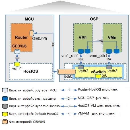
Fig. five
As can be seen in Figure 5, GE5 / 0/0/5 is the communication interface with the MCU and OSP, and the first DHCP-issued address will have to receive the br0 interface of the virtual switch. Check what address you got from the Gi0 / 0/5 interface address pool:
[AR169]display ip pool interface gigabitethernet0/0/5 used ----------------------------------------------------------------------------- Start End Total Used Idle(Expired) Conflict Disable ----------------------------------------------------------------------------- 192.168.2.1 192.168.2.254 253 1 252(0) 0 0 ----------------------------------------------------------------------------- Network section : ----------------------------------------------------------------------------- Index IP MAC Lease Status ----------------------------------------------------------------------------- 253 192.168.2.254 34a2-a2fc-edd8 36112 Used ----------------------------------------------------------------------------- Thus, the address 192.168.2.254 will be the main entry point into our virtual environment; it is this that needs to be addressed to switch to the virtual environment mode of the OSP card with the following command:
[AR169]virtual-environment 192.168.2.254 In this mode, you will have to download the operating system image from a pre-raised ftp server, as well as create and launch a virtual machine.
I picked up the FileZilla FTP server on the machine with the address 172.31.31.250 connected to the LAN switch of our device, i.e. to VLAN1:
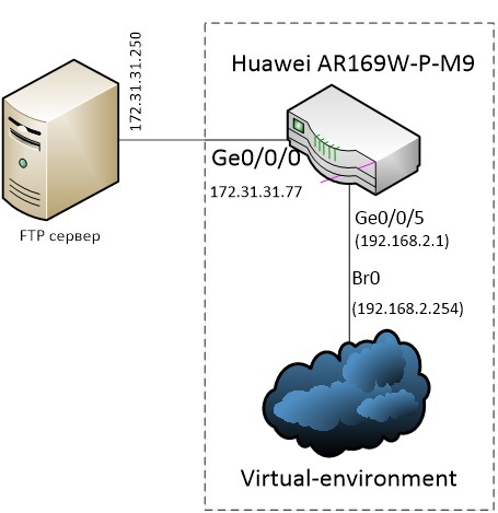
Pic.6
Important note. In my case, the router is not the default gateway for the FTP server, so I manually registered a static route to the 192.168.2.0 / 24 network on the ftp server via 172.31.31.77.
On the FTP server, user1 is connected to which a folder with a Windows 8.1 image is available - a file called win81.iso. Download it to our virtual environment:
[AR169]virtual-environment 192.168.2.254 [AR169-virtual-environment-192.168.2.254]download package win81.iso ftp ftp://172.31.31.250/win81.iso user user1 password cipher Enter Password(<1-16>): The download ratio is 100%. Info: Package downloading finished. Next, create an empty 30GB virtual disk for a future operating system:
[AR169-virtual-environment-192.168.2.254]blank-disk name disk1 size 30 We form an OVA-file from ISO with the parameters of our future virtual machine:
[AR169-virtual-environment-192.168.2.254]ova file win81 iso win81.iso disk disk1 cpu 4 memory 2800 network-card 1 network-card-type virtio extend-description "-hdb /dev/external_disk" Info: This operation will take several minutes, please wait.... Comments on the parameters of the ova file command:
• The first parameter will be the name of the created ova-file without an extension, i.e. win81;
• Parameter iso - our win81.iso file that was downloaded earlier;
• disk parameter - the name of the disk created by the blank-disk command, i.e. disk1
• Cpu - specify the number of processors from 1 to 4.
• Memory - the amount of RAM in gigabytes, in this case 2800 MB (if we use the extend-description in the previous command, then no more memory can be supplied).
• Network-card - the number of network cards of the virtual machine, in this case 1.
• Network-card-type - type of virtual card, three options are possible: e1000, rpl8139 and virtio. The recommended type for Windows is e1000.
• Extend-description - an important parameter that regulates the advanced settings of the virtual machine, such as an additional hard drive, serial interface, HDMI and Audio, as well as USB. If you do not describe these parameters, the virtual machine "will not see" the additional hard disk, which can be installed in our device, etc.
But there is an important limitation imposed by the device CLI - the entire command cannot be longer than 256 characters, and the USB or HDMI connection parameters exceed this limit.
For this case, the manual describes how to create an OVA file off-line, that is, not on this device, but on your linux machine. Here I will not give this description and I will use only one short parameter for connecting an external disk: "-hdb / dev / external_disk". Also important note when
And so, the ova-file is formed, you can proceed to the installation of a virtual machine from this assembly:
[AR169-virtual-environment-192.168.2.254]install vm win81 package win81.ova Info: This operation will take several minutes, please wait.. The virtual machine is installed, then we go into the management mode of the virtual machine, we will write the port number (for example, 8) by which it will be available later in the VNC viewer:
[AR169-virtual-environment-192.168.2.254]vm win81 [AR169-virtual-environment-vm-win81]vnc-server port 8 password cipher Enter Password(<6-8>): [AR169-virtual-environment-vm-win81] Then you can activate and start the virtual machine:
[AR169-virtual-environment-vm-win81]vm activate Info: VM activated successfully. [AR169-virtual-environment-vm-win81]vm start Info: VM started successfully. Check the state of the virtual machine with the following command, and also remember the name of its virtual interface (veth), it will be useful to us in the next step:
[AR169-virtual-environment-192.168.2.254]display vm win81 Name: win81 Status: running Package: win81.ova Auto-boot: enable Exception-action: alarm Cpu-shared: Current: 0 1 2 3 Next: Cpu-mono: Current: Next: Storage-claimed: Current: Disk: disk1 Target: sda Size: 30720M Next: Memory: Current: 2800M Next: Cdrom: Current: Name: win81.iso Type: private Next: Veth: Current: Name: win81_eth1 Mac: 0a:0b:1b:ce:e9:17 Next: From this output, you can see that the win81 virtual machine is in a neglected state, uses disk1 with a capacity of 30,720 MB as the main hard disk, 2800 MB of memory and its virtual network interface is called win81_eth. The next step is to connect this interface with the routing system of the router itself:
To do this, create a virtual interface veth2 for HostOS:
[AR169-virtual-environment-192.168.2.254]veth veth2 ... and create a virtual link between HostOS and the Win81 virtual machine (see Figure 5):
[AR169-virtual-environment-192.168.2.254]link veth veth2 to veth win81_eth1 Add the Host OS virtual interface to the vSwitch virtual switch:
[AR169-virtual-environment-192.168.2.254]ovs bridge br0 [AR169-virtual-environment-ovs-br0]port veth2 link-type access [AR169-virtual-environment-ovs-br0]quit All work on creating a virtual machine has been completed, you can proceed to its installation and work directly with it. For this, we will use the free VNC Viewer, having previously downloaded it from the developer’s website (RealVNC).
As the address, we specify our virtual interface 192.168.2.254:8 - and port 8, which we configured a little higher. In the connection settings, in the Expert section you should make sure the parameter FullColor = true, otherwise nothing will not work:
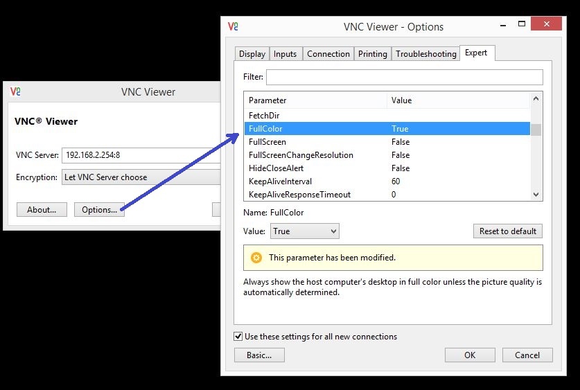
Fig. 7
Enter the password that we set in the vnc-server command and we see the initial screen for installing our guest operating system, in this case Windows 8.1:
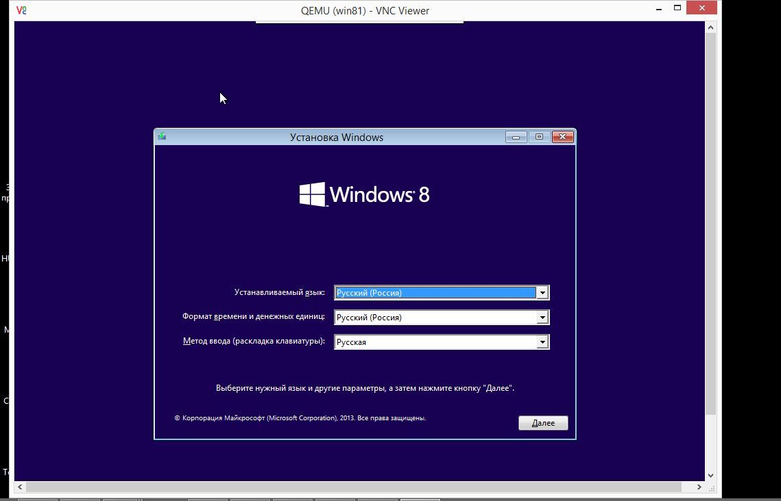
Fig. eight.
The process of installing Windows is no different than usual, so I’ll skip this point, we’ll assume that Windows was successfully installed and running. Immediately check that we have the network settings:
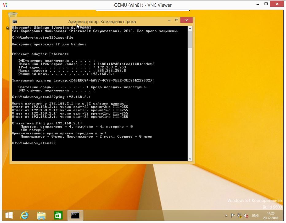
Fig. 9
As you can see, DHCP has issued the address 192.168.2.253 and we can ping the gateway 192.168.2.1. Thus, the network card was established normally and the virtual machine interacts with the router. It remains to release the virtual machine to the Internet (configure NAT on the router) and, for example, “push” the port outside for RDP access to the virtual machine (in this case, it is highly desirable to configure a static address from the 192.168.2.0/24 network card of the virtual machine rather than leaving it dynamic):
Create an Access-list to filter the hosts that need to provide Internet access, in this case the entire network 192.168.2.0 / 24:
[AR169]acl number 2001 [AR169-acl-basic-2001] rule permit source 192.168.2.0 0.0.0.255 [AR169-acl-basic-2001]quit We connect the cable from the provider to the GigabitEthernet0 / 0/4 (WAN) interface, let us be allocated the static address 195.19.XX.XX, the default gateway is 195.19.XX.1:
[AR169]interface GigabitEthernet0/0/4 [AR169-GigabitEthernet0/0/4]ip address 195.19.XX.XX 255.255.255.224 [AR169-GigabitEthernet0/0/4] nat outbound 2001 Let's translate the port from the external 33389 to the internal 3389 host of our virtual machine 192.168.2.254
[AR169-GigabitEthernet0/0/4] nat server protocol tcp global current-interface 33389 inside 192.168.2.253 3389 [AR169-GigabitEthernet0/0/4]quit Set the default route to the Internet:
[AR169] ip route-static 0.0.0.0 0.0.0.0 195.19.XX.1 Be sure to save the configuration:
[AR169]save Warning: The current configuration will be written to the device. Are you sure to continue?[Y/N]:Y It will take several minutes to save configuration file, please wait........... Configuration file had been saved successfully Note: The configuration file will take effect after being activated At this basic settings can be considered complete, one virtual machine was raised from the Windows 8.1 guest OS, the device software was updated, Internet access was made and the port was broadcast outside to access the OS using RDP.
')
Source: https://habr.com/ru/post/318014/
All Articles