About metastability in electronics
Many novice developers often underestimate the effect of asynchrony on the operation of digital circuits. In projects with one clock generator, difficulties do not arise: the circuit is completely synchronous, and the developer is only required to follow the requirements of Setup and Hold. But as soon as the second clock generator appears in the system, the problem of CDC - Clock Domains Crossing arises, which is connected with the asynchronous operation of circuit sections operating from independent (asynchronous) generators. In practice, this problem results in a complication of the design route associated with the features of static time analysis in CAD, and in the gland there is an effect such as metastability and anomalous behavior of triggers. Actually, we have already written about metastability here , but I suggest a little deeper understanding of the problem.
At the beginning of a few introductory words. About such critical trigger parameters as setup and hold is described in detail here . In a nutshell, near the moment of arrival of the clock signal at the trigger input, there exists a certain minimum time interval within which the signal at the information input must remain stable. If a change in signal occurs outside this interval, the trigger fires correctly. These are the minimum requirements that a developer must follow when designing a circuit with one clock generator. And even if the project uses several multiple frequencies derived from a single reference, the circuit is also considered synchronous, and the maximum that should be taken care of in the design is compliance with Setup and Hold.
Now imagine that the project uses two independent sources of clocking. All triggers in the scheme are divided into two domains, according to the principle of control from one or the other reference frequency. Between these domains, which are asynchronous to each other, the border passes in the form of signals, formed at one reference frequency, and triggers operating at another frequency, which enter the information inputs. In fact, the signal at the inputs of the triggers is asynchronous to their clock pulse, which means that the required Setup and Hold times cannot be sustained. As a result, in the triggers at the border of two domains, anomalies rarely arise (in fact, failures), which in time modeling is usually designated as the undefined state of trigger X, and painted in red on the waveform. In a real circuit, this anomalous state of a trigger may turn out to be just a prolonged triggering, since for a trigger to fall into the metastability region, the input signal must change in a much narrower period of time than ts + th:

The figure shows: tc is the absolute time of arrival of the clock edge, which is a zero count for the Hold axis (pointing from zero to the right), and the Setup axis. The Setup axis is directed to the left, since the installation time is counted in the negative direction from the moment of arrival of the front of the clock. Further, ts and th — the Setup and Hold parameters of the trigger: between the ts and th marks, the signal at the trigger's information input must be stable (the red area of the figure). Outside the ts + th window, the signal can change arbitrarily (blue area of the figure). When the signal inside the ts + th window changes, trigger flip can take a long time. The last element of the picture is the area of metastability, highlighted in orange. This is a certain time interval, when hit in which the behavior of the trigger outputs becomes unpredictable, which will be described in detail below. In practice, the time th is often negative (the ts + th window is shifted to the left relative to zero for one reason or another), and the width of the metastability region must be determined individually for each trigger circuit and transistor parameters - experimentally or using spice modeling.
')
Consider the device of the classical D-flip-flop scheme and its RS-latch component:

Imagine that a short pulse with an active zero arrives at the R (Reset) input of the latch, and a passive signal at the S (Set) input (log. 1). If the pulse is quite short, the latch may not switch. And if you increase the duration of the pulse? We will conduct a series of experiments, applying to the input of the latch pulses of different durations. The following figure is taken from the L.R. Marino General Theory of Metastable Operation:

The figure shows two axes - the voltage on the X and Y outputs of the RS-latch. Mark V0 and V1 - voltage log. 1 and log. 0 trigger outputs, and Vm - voltage equal to ½ U power. The figure also shows that the initial state is at the point of the plane {X = V1, Y = V0} - the trigger outputs {X, Y} took logical values {1.0}. A high potential (passive value) is applied to the S (Set) latch input, and a pulse with an active zero of different duration is applied to the R (Reset) input (6 is the shortest, 1 is the longest - shown at the bottom of the figure). In accordance with the pulse number at the input R, the figure shows 6 potential switching trajectories of a pair of outputs {Y, X}: for pulses 1-3, a full switching of the trigger occurs, for pulses 5-6 the trigger does not switch, and the trajectory 4 causes the trigger to center metastability zones (point {Vm, Vm}), located in the middle between the thresholds of the log. 1 and log. 0
So, we have shown that by applying a latch on one shoulder of an impulse of insufficient duration, its energy may not be enough to fully switch. With a large pulse duration, the latch must switch. And, finally, you can pick up the input pulse of such a duration that the latch outputs will be in the middle between two stable states. At the same time, the closer to the area of metastability the pulse energy pushes the outputs of the latch, the longer these outputs restore the stable state.
Now we turn to the modern D-flip-flop scheme from the 65nm library used in designing ASICs:

The diagram on the information input D is the GD key, the first latch is depicted as two inverters in the counter-switching I1 and G1, the pass-key SW separates the latch, and the second latch is also built on the two inverters in the counter-switching I2 and G2. The output for increasing the speed is taken from the left shoulder of the second latch. The trigger works as follows: when CK = 0, the input key passes the signal to the first latch with the G1 feedback disabled, the key between the latches is closed, and the second latch is in storage, because G2 feedback is active. When CK = 1, the first latch is cut off from the D input, the G1 feedback is activated, the key between the latches is unlocked, and the second latch turns off the feedback - the data from the first latch are copied to the second. If the signal D is removed before the arrival of the leading edge CK, we receive an impulse with active zero at the input of the first latch, whose duration depends only on the ratio of the fronts CK and D. Thus, the situation is similar to that with the RS latch: the pulse energy on one of the arms can switch the latch, do not switch, or - enter the latch in a state of metastability. The article L.R. Marino proved mathematically that the outputs of absolutely any trigger, regardless of its design, can assume a metastable state.
Let's try to consider all possible states of the latch outputs; for this, we construct another graph with two axes-potentials of the outputs. The schedule was borrowed from lectures on logical design by Dr. Sc., Professor V. B. Marakhovsky:
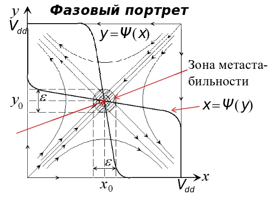
The schedule is almost the same as in the article by L.R. Marino, but the arrows show the trajectories of the possible behavior of the latch outputs. Moving along the paths, the latch outputs will eventually switch to the stable logical state {1,0} or {0,1}, corresponding to the state at the inputs (the state of the input will latch). But when the potential of the outputs falls into a certain area in the center of the graph, it is impossible to predict the final state of the outputs. This is an area of unstable equilibrium (metastability), the output of which can be influenced only by random factors, such as thermal noise. The final state of the latch outputs at the completion of the metastability is not known in advance — it can be any ({1.0} or {0.1}). The size of the metastability region is measured experimentally, or is calculated using spice modeling. It should be noted that in practice, metastability manifests itself not only in the form of a static potential equal to ½ U of power, but also in the form of weak pulsations near this point. Another important property of metastability is the unpredictability of the time it takes for the latch to become stable. As it is known, the time it takes for a latch to exit a metastable state is described by the Poisson distribution, and in theory it can be infinitely long. Thus, it is impossible to predict in advance not only the final state of the trigger after the exit from metastability, but also the duration of the metastable state in time. However, if the signal at the trigger input does not change in the next cycle, then the maximum duration of the metastable state of the trigger outputs at the boundary of the two domains does not exceed the duration of the clock pulse.
Formulas and methods for calculating the size of the metastability region and failure rate can be found in the article Variability in Multistage Synchronizers. I will give only the results of calculations of the frequency of failures from this article. As a synchronizer, we used serial circuits of 2, 3, and 4 triggers, operating on a pulse with a period of 800 ps, and the frequency range of the input signal from 600 ps to 2 ns.

On the graph, the vertical axis shows MTBF in years - the period between failures (getting into a metastable state - a failure) when using different synchronizers at the entrance to the domain, operating from a cycle with a period of 800 ps. Horizontally, the period of the clock pulse of the domain - signal source. As can be seen from the figure, the more triggers in the synchronizer chain, the less often there are failures.
1. The switching time of the trigger depends entirely on the duration of the control pulse at the input of the first latch, which is obtained by shifting the phase of the signal arrival to the clock pulse at the trigger inputs. When switching a signal outside the interval ts + th, the trigger switches correctly, and for a predetermined time. But, if the input signal has changed within this interval, then the trigger reaches a stable state the longer, the closer to the metastability zone it is. If the trigger outputs are inside the metastability zone, their final logical state and response time cannot be predicted.
2. The metastability of the trigger outputs on the oscilloscope looks like the potential level of the outputs, equal to ½ U of power, or like weak pulsations near this level. In this case, in the inverters of the trigger circuit flows a through current between the ground and power buses. But since the resistance of an open channel in n- and p-transistors is measured in kilo-ohms, the through current does not have a noticeable effect on such phenomena as total circuit consumption, power drawdown (IR drop), and electromigration.
3. At frequencies near gigahertz, a failure (due to metastability) in a trigger at the boundary of two domains occurs every few seconds. The use of two or more consecutive triggers as a synchronizer helps combat metastability. When using two triggers, the synchronizer output fails once a year; three triggers - once per thousand years; four triggers - once every 10 billion years. Reducing the operating frequency affects the frequency of failures exponentially: when using a synchronizer of two triggers and a frequency of about 500 MHz, the interval of failures will increase by several orders of magnitude to one failure per million years. Therefore, if you are designing a scheme with frequencies under gigahertz, try to use as few asynchronous domains as possible, or increase the number of sequentially enabled triggers in synchronizers to three.
4. The frequency of failures is strongly influenced by the parasitic capacitances of the outputs of the first and second latches (components of the trigger), which depend on the parameters of the used transistors and on the trigger circuit. In other words, by changing the parameters of transistors and the trigger circuit, one can indirectly influence the frequency of occurrence of metastability at the outputs of this trigger. The recipe is suitable only if you are designing your own library of items.
5. From the point of view of static time analysis, all paths between asynchronous domains should be described by sdc set_false_path.
The metastability of triggers in Russia is not studied by anyone (correct, if not right), but in practice it is enough for the developer to follow the simple guidelines given above; I hope it will be useful to someone.
At the beginning of a few introductory words. About such critical trigger parameters as setup and hold is described in detail here . In a nutshell, near the moment of arrival of the clock signal at the trigger input, there exists a certain minimum time interval within which the signal at the information input must remain stable. If a change in signal occurs outside this interval, the trigger fires correctly. These are the minimum requirements that a developer must follow when designing a circuit with one clock generator. And even if the project uses several multiple frequencies derived from a single reference, the circuit is also considered synchronous, and the maximum that should be taken care of in the design is compliance with Setup and Hold.
Now imagine that the project uses two independent sources of clocking. All triggers in the scheme are divided into two domains, according to the principle of control from one or the other reference frequency. Between these domains, which are asynchronous to each other, the border passes in the form of signals, formed at one reference frequency, and triggers operating at another frequency, which enter the information inputs. In fact, the signal at the inputs of the triggers is asynchronous to their clock pulse, which means that the required Setup and Hold times cannot be sustained. As a result, in the triggers at the border of two domains, anomalies rarely arise (in fact, failures), which in time modeling is usually designated as the undefined state of trigger X, and painted in red on the waveform. In a real circuit, this anomalous state of a trigger may turn out to be just a prolonged triggering, since for a trigger to fall into the metastability region, the input signal must change in a much narrower period of time than ts + th:
The figure shows: tc is the absolute time of arrival of the clock edge, which is a zero count for the Hold axis (pointing from zero to the right), and the Setup axis. The Setup axis is directed to the left, since the installation time is counted in the negative direction from the moment of arrival of the front of the clock. Further, ts and th — the Setup and Hold parameters of the trigger: between the ts and th marks, the signal at the trigger's information input must be stable (the red area of the figure). Outside the ts + th window, the signal can change arbitrarily (blue area of the figure). When the signal inside the ts + th window changes, trigger flip can take a long time. The last element of the picture is the area of metastability, highlighted in orange. This is a certain time interval, when hit in which the behavior of the trigger outputs becomes unpredictable, which will be described in detail below. In practice, the time th is often negative (the ts + th window is shifted to the left relative to zero for one reason or another), and the width of the metastability region must be determined individually for each trigger circuit and transistor parameters - experimentally or using spice modeling.
')
Consider the device of the classical D-flip-flop scheme and its RS-latch component:
Imagine that a short pulse with an active zero arrives at the R (Reset) input of the latch, and a passive signal at the S (Set) input (log. 1). If the pulse is quite short, the latch may not switch. And if you increase the duration of the pulse? We will conduct a series of experiments, applying to the input of the latch pulses of different durations. The following figure is taken from the L.R. Marino General Theory of Metastable Operation:
The figure shows two axes - the voltage on the X and Y outputs of the RS-latch. Mark V0 and V1 - voltage log. 1 and log. 0 trigger outputs, and Vm - voltage equal to ½ U power. The figure also shows that the initial state is at the point of the plane {X = V1, Y = V0} - the trigger outputs {X, Y} took logical values {1.0}. A high potential (passive value) is applied to the S (Set) latch input, and a pulse with an active zero of different duration is applied to the R (Reset) input (6 is the shortest, 1 is the longest - shown at the bottom of the figure). In accordance with the pulse number at the input R, the figure shows 6 potential switching trajectories of a pair of outputs {Y, X}: for pulses 1-3, a full switching of the trigger occurs, for pulses 5-6 the trigger does not switch, and the trajectory 4 causes the trigger to center metastability zones (point {Vm, Vm}), located in the middle between the thresholds of the log. 1 and log. 0
So, we have shown that by applying a latch on one shoulder of an impulse of insufficient duration, its energy may not be enough to fully switch. With a large pulse duration, the latch must switch. And, finally, you can pick up the input pulse of such a duration that the latch outputs will be in the middle between two stable states. At the same time, the closer to the area of metastability the pulse energy pushes the outputs of the latch, the longer these outputs restore the stable state.
Now we turn to the modern D-flip-flop scheme from the 65nm library used in designing ASICs:
The diagram on the information input D is the GD key, the first latch is depicted as two inverters in the counter-switching I1 and G1, the pass-key SW separates the latch, and the second latch is also built on the two inverters in the counter-switching I2 and G2. The output for increasing the speed is taken from the left shoulder of the second latch. The trigger works as follows: when CK = 0, the input key passes the signal to the first latch with the G1 feedback disabled, the key between the latches is closed, and the second latch is in storage, because G2 feedback is active. When CK = 1, the first latch is cut off from the D input, the G1 feedback is activated, the key between the latches is unlocked, and the second latch turns off the feedback - the data from the first latch are copied to the second. If the signal D is removed before the arrival of the leading edge CK, we receive an impulse with active zero at the input of the first latch, whose duration depends only on the ratio of the fronts CK and D. Thus, the situation is similar to that with the RS latch: the pulse energy on one of the arms can switch the latch, do not switch, or - enter the latch in a state of metastability. The article L.R. Marino proved mathematically that the outputs of absolutely any trigger, regardless of its design, can assume a metastable state.
Let's try to consider all possible states of the latch outputs; for this, we construct another graph with two axes-potentials of the outputs. The schedule was borrowed from lectures on logical design by Dr. Sc., Professor V. B. Marakhovsky:
The schedule is almost the same as in the article by L.R. Marino, but the arrows show the trajectories of the possible behavior of the latch outputs. Moving along the paths, the latch outputs will eventually switch to the stable logical state {1,0} or {0,1}, corresponding to the state at the inputs (the state of the input will latch). But when the potential of the outputs falls into a certain area in the center of the graph, it is impossible to predict the final state of the outputs. This is an area of unstable equilibrium (metastability), the output of which can be influenced only by random factors, such as thermal noise. The final state of the latch outputs at the completion of the metastability is not known in advance — it can be any ({1.0} or {0.1}). The size of the metastability region is measured experimentally, or is calculated using spice modeling. It should be noted that in practice, metastability manifests itself not only in the form of a static potential equal to ½ U of power, but also in the form of weak pulsations near this point. Another important property of metastability is the unpredictability of the time it takes for the latch to become stable. As it is known, the time it takes for a latch to exit a metastable state is described by the Poisson distribution, and in theory it can be infinitely long. Thus, it is impossible to predict in advance not only the final state of the trigger after the exit from metastability, but also the duration of the metastable state in time. However, if the signal at the trigger input does not change in the next cycle, then the maximum duration of the metastable state of the trigger outputs at the boundary of the two domains does not exceed the duration of the clock pulse.
Formulas and methods for calculating the size of the metastability region and failure rate can be found in the article Variability in Multistage Synchronizers. I will give only the results of calculations of the frequency of failures from this article. As a synchronizer, we used serial circuits of 2, 3, and 4 triggers, operating on a pulse with a period of 800 ps, and the frequency range of the input signal from 600 ps to 2 ns.
On the graph, the vertical axis shows MTBF in years - the period between failures (getting into a metastable state - a failure) when using different synchronizers at the entrance to the domain, operating from a cycle with a period of 800 ps. Horizontally, the period of the clock pulse of the domain - signal source. As can be seen from the figure, the more triggers in the synchronizer chain, the less often there are failures.
findings
1. The switching time of the trigger depends entirely on the duration of the control pulse at the input of the first latch, which is obtained by shifting the phase of the signal arrival to the clock pulse at the trigger inputs. When switching a signal outside the interval ts + th, the trigger switches correctly, and for a predetermined time. But, if the input signal has changed within this interval, then the trigger reaches a stable state the longer, the closer to the metastability zone it is. If the trigger outputs are inside the metastability zone, their final logical state and response time cannot be predicted.
2. The metastability of the trigger outputs on the oscilloscope looks like the potential level of the outputs, equal to ½ U of power, or like weak pulsations near this level. In this case, in the inverters of the trigger circuit flows a through current between the ground and power buses. But since the resistance of an open channel in n- and p-transistors is measured in kilo-ohms, the through current does not have a noticeable effect on such phenomena as total circuit consumption, power drawdown (IR drop), and electromigration.
3. At frequencies near gigahertz, a failure (due to metastability) in a trigger at the boundary of two domains occurs every few seconds. The use of two or more consecutive triggers as a synchronizer helps combat metastability. When using two triggers, the synchronizer output fails once a year; three triggers - once per thousand years; four triggers - once every 10 billion years. Reducing the operating frequency affects the frequency of failures exponentially: when using a synchronizer of two triggers and a frequency of about 500 MHz, the interval of failures will increase by several orders of magnitude to one failure per million years. Therefore, if you are designing a scheme with frequencies under gigahertz, try to use as few asynchronous domains as possible, or increase the number of sequentially enabled triggers in synchronizers to three.
4. The frequency of failures is strongly influenced by the parasitic capacitances of the outputs of the first and second latches (components of the trigger), which depend on the parameters of the used transistors and on the trigger circuit. In other words, by changing the parameters of transistors and the trigger circuit, one can indirectly influence the frequency of occurrence of metastability at the outputs of this trigger. The recipe is suitable only if you are designing your own library of items.
5. From the point of view of static time analysis, all paths between asynchronous domains should be described by sdc set_false_path.
The metastability of triggers in Russia is not studied by anyone (correct, if not right), but in practice it is enough for the developer to follow the simple guidelines given above; I hope it will be useful to someone.
Source: https://habr.com/ru/post/317514/
All Articles