Segment routing: how and why
The article does not cover the basics of MPLS, and the author expects the reader to be at least well versed in terminology.
What is wrong with LDP and RSVP? First, this is an additional control plane protocol, which must closely and in the correct order interact with the IGP. Hence
ldp igp sync in Cisco terminology and other great IGP-LDP interoperability management techniques. Incorrectly configured interface may result in traffic dropping. Such problems are not always easy to diagnose and fix. Secondly, any control plane protocol consumes hardware resources. In particular, for classic IOS, additional processes are also dangerous due to the fact that the entire OS operates in the same memory space. In other words, segfault in one application can cause crash of the entire device. In theory. In fact, LDP and RSVP work for most vendors well and stably. But we, as avid optimizers, of course, would like to get rid of them. From the point of view of forwarding, segment routing can be implemented using MPLS and IPv6 protocols. It will be exclusively about the forwarding plane with MPLS.Getting rid of LDP
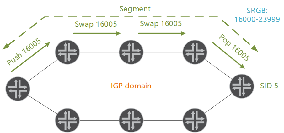
The SPRING working group proposed to shift the functions of label distribution protocols to the IGP, and to build the LSP with segments . A segment is part (or all) of the LSP to a particular router. To assign tags, the selected range is used so as not to overlap with classical protocols. It is called SRGB - segment routing global block. This block may differ on different devices, although if possible it is better to use the same one in order not to get confused. However, the label to achieve a specific PE must be unique. In this case, the label on the entire segment does not change. It is important to understand that the swap operation is performed anyway, just the in and out labels are the same. By default, devices on the IOS XR platform use the values of 16000-23999 for SRGB. And, since the blocks may differ, information about them is announced through IGP.
With the block it is clear. But how do routers agree on the label value for a specific FEC? Each device must be configured with a unique SID - segment identifier. There are Node SID and Adjacency SID, about the latter - just below. To determine the label that will be assigned to the loopback device, the Node SID is added to the lower SRGB border. For example, if SRGB starts at 16000 and the device is assigned SID 5, then the label to reach the loopback of the device will be equal to 16005. This label will be used by all devices on the way (swap 16005 -> 16005).
router isis SR net 49.0000.0000.0001.00 address-family ipv4 unicast metric-style wide level 2 segment-routing mpls sr-prefer ! SR IGP ! LDP interface lo0 address-family ipv4 unicast prefix-sid index 5 ! SID loopback PE Why suddenly it was about lupbekah? The fact is that SR is a technology for building a path to a specific PE device. In other words, we are talking about transport labels. And to reach a PE device is to reach its lupback. The distribution and assignment of service tags, whether L2VPN, L3VPN or other technologies, does not change. All the same MP-BGP will be needed to build services, all the same service tags will be located at the bottom of the stack.
')
Just above, I said that the device SID must be unique. So, this is a blatant lie. Adjacency SID has a local value. The router generates an Adjacency SID for each SR neighbor automatically, and the value does not overlap with the SRGB. Configure nothing in this case. Like everything else, these tags are distributed by the IGP protocol. This makes it possible to pass traffic through a specific interface. How to specify the interface if the label may not be unique? Everything is simple: a stack of labels is used for this, where the upper label is the Node SID and the lower one is the Adjacency SID.

Getting rid of RSVP
LDP is good for everyone, but it only follows the path that the IGP chose, and the band does not know how to reserve. If it is necessary to build a traffic transmission path different from what IGP chose, RSVP-TE with its explicit paths comes to the rescue. In the case of building a path that differs from the best one in IGP's opinion, SR can replace RSVP functionality right out of the box: simply create a label stack that completely describes the path. For example, if we need traffic to go through Router A to Router B, the SID Router A will be in the transport label stack and then Router B SID.

Frankly speaking, from the point of view of configuration, little changes: in the explicit path all the same IP addresses are used. And immediately the answer to the frequently asked question: yes, the overhead projector is increasing. If you need to accurately determine the path of the ten routers, then there will be 10 labels in the stack. However, such scenarios are very rare in practice. Usually there are a few tags left to solve a specific task.
router isis SR address-family ipv4 unicast mpls traffic-eng level-2 mpls traffic-eng router-id Loopback0 ! ! interface tunnel-te10 ipv4 unnumbered loopback0 destination 192.168.0.1 path-selection segment-routing adjacency protected ! protected - FRR path-option 1 explicit name PATH1 segment-routing ! explicit-path RSVP And how to reserve a strip? This is still difficult. Now there is no problem in order to run CSPF. The problem is that bandwidth reservation requires a state on the router that describes the value of the reserved gateway for each LSP. Therefore, the concept of band reservation requires the introduction of the concept of PCE.
PCE — The path computation element is a controller that communicates with routers using the PCEP protocol. This controller can calculate TE tunnels using CSPF, including the bandwidth attribute. Note that PCE and SR are not the only existing combination. With no less success, PCE can work with RSVP, LDP, and even statically assign labels. In the general case, the PCE's task is to install the forwarding state to the device immediately via the PCEP protocol.

Of course, to calculate the path, PCE must know the existing topology. You can tell PCE about the topology by making it part of the topology, that is, connecting it to the IGP domain. An alternative is a BGP-LS session with a controller.
PCE is able to track the current load of interfaces and rebuild the tunnel path if required. In other words, this element can be called an SDN controller on top of an existing MPLS network. However, even a brief description of the PCE is a topic for at least a separate article. Therefore, I will leave here links to popular open source projects that support PCEP in one form or another: this is ONOS and ODL — and we will return to SR.
What is the result?
Everything looks very beautiful and optimistic, but where does it apply? Let's look at a few scenarios.
1. Replacing the LDP protocol.
We figured out that replacing RSVP without PCE would be difficult when using bandwidth reservation. Therefore, we will not consider a complete replacement of RSVP without additional elements in the SR network. As for LDP, in theory, this protocol can be turned off and transport tags distributed via IGP. However, this scenario hardly brings enough benefits, given the risks that will have to be taken when redesigning the network. In addition, not always every device on the network supports SR. This can be solved with additional configuration, when several devices are the boundary between the SR and LDP domain. However, the fact of having such a configuration makes you think more about the pros and cons of the solution. Frankly, there is no reason to replace LDP with SR just to replace.
2. Topology independent LFA.
LFA or IP FRR does not work in arbitrary topologies. For example, in a ring topology, the router will not be able to calculate the siding, since either path will result in a loop. However, using MPLS encapsulation, traffic can be dropped not only to a neighbor, but also to a remote device. Here SR has a practical meaning. Of course, the same problem can be solved with RSVP, but the solution with SR looks more elegant.
As an example, consider the mentioned ring topology, where the OSPF cost between all routers is the same. Suppose each router calculates an LFA for a particular path.

As you can see, the only alternative route for IP routing is looping. In other words, it is impossible to calculate the LFA in a pure IP network. Therefore, it is necessary to “reset” the traffic a little closer to the reserved prefixes, for which SR is perfect.
router isis SR interface Gi0/0/0/1 address-family ipv4 unicast fast-reroute per-prefix ! LFA. fast-reroute per-prefix ti-lfa ! TI LFA 3. SDN.
Use of SR in conjunction with PCE. Here, both RSVP can be replaced, and the band can be dynamically tracked, and the API can be organized for third-party tools. Of course, this list is poor and does not claim to be a complete list of everything that can be achieved with the introduction of PCE into the network. But from a transport point of view, the head of everything will be the flexibility of network management, the ability to configure intra-AS LSPs (including TE, L2VPN, etc.), ease of configuration and deployment of services. In addition, PCE does not require network redesign and can work on top of an existing forwarding plane.
Here again I was carried a little away from SR. However, the SR + PCE bundle looks very promising. And precisely in this bundle segment routing reveals all its advantages.
4. Traffic management in large networks.
Cisco has a non-trivial approach to building large carrier networks called Unified MPLS . In another terminology, the same approach may be called Seamless MPLS. Networks with SR can be an excellent and more transparent alternative to this approach.
If you can imagine how much effort you need to make to design and configure your network using Unified MPLS from scratch, SR may appeal to you.
LDP and SR interaction
I intentionally left this section for last. Firstly, it is not always necessary that SR and LDP interact. Secondly, it would be nice to understand what tasks can be solved using SR before proceeding to the issues of interaction with the LDP.
The most frequently resolved interoperability issues arise during migration from LDP to SR or in the absence of SR support on some devices in the network. The IOS XR SR configuration is safe. By default, labels received via LDP have higher priority. In order for LDP to go into the background, you need to tell the router the
segment-routing mpls sr-prefer in the IGP process. At the same time, it is not necessary to make SR preferred on all routers at once. This command is local, and the fact that SR is preferred is not communicated to other devices on the network.If there are devices that do not support SR, you need to configure several devices as a Mapping server . I speak only for reasons of fault tolerance - one device at the border of SR / LDP networks will be enough for operation.
A mapping server receives labels over LDP, and then announces SIDs on behalf of devices that cannot SR. At the same time, the data plane should not pass through the mapping server - this is a control plane device. All mappings that the server invented are advertised to its clients via IGP. Each device must be configured as a client in order to receive mappings for LDP networks.
The mappings themselves are set manually. In this case, if two or more mapping servers are used, it is expected that their mappings will be configured identically. Of course, the network will not break from an incorrectly configured mapping, but in case of an accident, convergence may suffer.
! Server segment-routing mapping-server prefix-sid-map address-family ipv4 10.10.20.1/32 254 range 255 ! SID (10.10.20.1,2 ... 255) ! SID ! 32. 10.10.10.10/32 400 ! SID /32 ! ! ! router isis GEOR address-family ipv4 unicast segment-routing prefix-sid-map advertise-local ! IS-IS ! Client router isis GEOR address-family ipv4 unicast segment-routing prefix-sid-map receive ! . With a mapping server, you can protect LSPs built with the LDP protocol in TI LFA. In other words, MPLS services for which labels are generated by classic protocols can be protected using SR.
There are many LDP and SR interaction scenarios, including LDPoSR and SRoLDP. A slightly more detailed description can be found on one of the links below.
This concludes my short segment routing narrative. I want to note that the material in the article does not consider all the nuances of the SR and leaves much behind the scenes. Much of what is left overs can be found at the links below.
Thank you for attention.
Links to IETF resources:
» SR draft
» PCEP
Very useful resource on SR: Cisco SR
One of the sessions on Cisco Live: Introduction to Segment Routing
Source: https://habr.com/ru/post/317158/
All Articles