STM32: FreeRTOS and Piezo Ceramic Emitter
A ceramic piezo emitter (buzzer) is a simple piece that, along with an LED, requires a minimum set of resources for control and is just as easily connected to a microcontroller. Like the LED with the ability to smoothly adjust the brightness, the microcontroller requires no more than one channel of the timer and external output.
There are a lot of lessons on the Internet “We connect the squeaker to the Arduino”, only now they end up playing “A grasshopper sitting in the grass” or the voice acting of the RFID sensor. Probably those who are engaged in this professionally and seriously, not to blogging and video recording.
')
But the miniature ceramic speaker is a step towards a more friendly interface with a man. Pressing buttons, touching the touch panel, the reaction to various events ... Such is the feedback in the form of a sound response!
We will try to do something with this under the cut, namely, write the driver for piezo dynamics and make it sound in parallel with several different external events.
Glands
We will use a homemade board with a stm32f103 microcontroller in a 144-foot package and a PKLCS1212E 40 A1-R1 piezo emitter from Murata.

This simple element is a ceramic plate, to the plates of which a signal of a certain frequency is given. As a result, the plate oscillates itself and vibrates the air, and we hear a sound. It makes no sense to bring the circuit board, but the connection of the tweeter is worth showing:
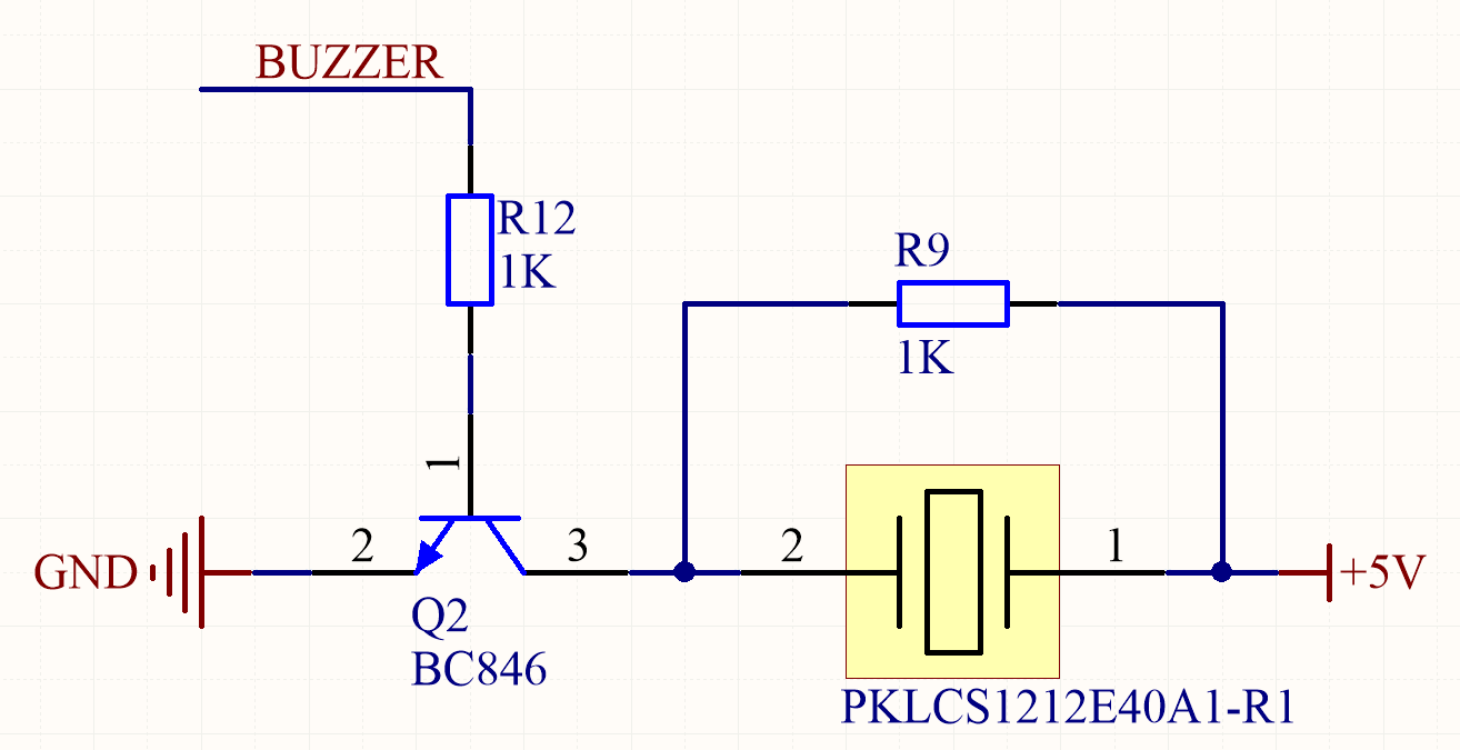
Pyezodinamik is turned on through the transistor and it is made for greater loudness of the sound (swinging with an amplitude of 5V), although you can hang it directly on the leg of the microcontroller (3.3V). The documentation on it contains the frequency response, from which it can be seen that the maximum amplitude is achieved at an input signal of 4 kHz. And in the component part number ( PKLCS1212E 40 A1-R1 ) this is reflected ( Expressed resonant frequency by two-digit alphanumerics. The unit is 100 hertz (Hz.) 4kHz (4000Hz) is denoted as "40." ).

We will work with sound, and here I will not dare to tell something deeper than the basics, since I myself have minimal knowledge: there are frequencies that the speaker can reproduce, there is an octave system with which you can group, name the main frequencies, and Throw this data into an array. We will work with him:
u16 GL_BuzzerAllNotes[] = { 261, 277, 294, 311, 329, 349, 370, 392, 415, 440, 466, 494, 523, 554, 587, 622, 659, 698, 740, 784, 831, 880, 932, 988, 1046, 1109, 1175, 1245, 1319, 1397, 1480, 1568, 1661, 1760, 1865, 1976, 2093, 2217, 2349, 2489, 2637, 2794, 2960, 3136, 3322, 3520, 3729, 3951, 4186, 4434, 4699, 4978, 5274, 5588, 5920, 6272, 6645, 7040, 7459, 7902}; #define OCTAVE_ONE_START_INDEX (0) #define OCTAVE_TWO_START_INDEX (OCTAVE_ONE_START_INDEX + 12) #define OCTAVE_THREE_START_INDEX (OCTAVE_TWO_START_INDEX + 12) #define OCTAVE_FOUR_START_INDEX (OCTAVE_THREE_START_INDEX + 12) #define OCTAVE_FIVE_START_INDEX (OCTAVE_FOUR_START_INDEX + 12) #define BUZZER_DEFAULT_FREQ (4186) //C8 - 5th octave "Do" #define BUZZER_DEFAULT_DURATION (20) //20ms #define BUZZER_VOLUME_MAX (10) #define BUZZER_VOLUME_MUTE (0) Piezodinamika driver
Pyezodinamik is not a LED, pulse-width modulation with a constant frequency and a variable pulse ratio does not work here. The leg, on which the control transistor hangs (PA15, TIM2, CH1), is tuned in the PWM mode:
void BuzzerConfig (void)
void BuzzerConfig(void) { GPIO_InitTypeDef GPIO_Options; TIM_TimeBaseInitTypeDef TIM_BaseOptions; TIM_OCInitTypeDef TIM_PWM_Options; RCC_APB2PeriphClockCmd(BUZZER_CLK_PINS | RCC_APB2Periph_AFIO, ENABLE); RCC_APB1PeriphClockCmd(RCC_APB1Periph_TIM2, ENABLE); GPIO_PinRemapConfig(GPIO_Remap_SWJ_JTAGDisable, ENABLE); GPIO_PinRemapConfig(GPIO_PartialRemap1_TIM2, ENABLE); //PA.15 TIM2_CH1, BUZZER GPIO_Options.GPIO_Pin = BUZZER_PIN; GPIO_Options.GPIO_Speed = GPIO_Speed_10MHz; GPIO_Options.GPIO_Mode = GPIO_Mode_AF_PP; GPIO_Init(BUZZER_PORT, &GPIO_Options); TIM_BaseOptions.TIM_Period = 2 * BUZZER_VOLUME_MAX - 1; TIM_BaseOptions.TIM_ClockDivision = TIM_CKD_DIV1; TIM_BaseOptions.TIM_CounterMode = TIM_CounterMode_Up; TIM_TimeBaseInit(TIM2, &TIM_BaseOptions); TIM_PWM_Options.TIM_OCMode = TIM_OCMode_PWM1; TIM_PWM_Options.TIM_OutputState = TIM_OutputState_Enable; TIM_PWM_Options.TIM_OutputNState = TIM_OutputNState_Disable; TIM_PWM_Options.TIM_OCPolarity = TIM_OCPolarity_High; TIM_PWM_Options.TIM_Pulse = 0; TIM_OC1Init(TIM2, &TIM_PWM_Options); TIM_OC1PreloadConfig(TIM2, TIM_OCPreload_Enable); TIM_ARRPreloadConfig(TIM2, ENABLE); TIM_Cmd(TIM2, ENABLE); } The code does not contain an important timer setting parameter - a clock pre-splitter. We will change it dynamically, and we will achieve the generation of sound of the desired frequency.
Obviously, changing the frequency of the signal leads to a change in sound, but what about the pulse ratio? I did not find anything useful on this issue in the documentation, but there was an assumption that changing the duty ratio entails a change in volume. If this is true, then the meander (duty ratio = 50%) will give the maximum volume, and convergence to 0% (or symmetrically, to 100%) will reduce the volume, finally, to zero. It really works so-so, so I just turn the beeper on and off using the following two macros:
#define BUZZER_VOLUME_MAX 10 #define BUZZER_VOLUME_MUTE 0 BUZZER_VOLUME_MAX - this is the number of pulses, which is twice laid out in the required period of work, which is inversely proportional to the frequency. We know the required frequency (setting), the period is also clear (x2), and therefore the predecessor for the timer will not be difficult to find. In STM32, it is any number from 1 to 0xFFFF.
Wrap all actions in the frequency setting function:
void BuzzerSetFreq(u16 freq) { TIM2->PSC = (SYSCLK_FREQ / (2 * BUZZER_VOLUME_MAX * freq)) - 1; //prescaller } And changing the duty cycle to set the volume:
void BuzzerSetVolume(u16 volume) { if(volume > BUZZER_VOLUME_MAX) volume = BUZZER_VOLUME_MAX; TIM2->CCR1 = volume; } Everything, the driver of a tweaker is ready You can play something, after creating an array of frequencies (and durations would be nice).
Happy birthday
u32 HappyBirthday[] = { 262, 262, 294, 262, 349, 330, 262, 262, 294, 262, 392, 349, 262, 262, 523, 440, 349, 330, 294, 466, 466, 440, 349, 392, 349}; for(i = 0; i < sizeof(HappyBirthday) / sizeof(u32); i++) { BuzzerSetFreq(HappyBirthday[i]); BuzzerSetVolume(BUZZER_VOLUME_MAX); DelayTime(400); BuzzerSetVolume(BUZZER_VOLUME_MUTE); } Piezodinamik as a shared resource
The global idea is to create a convenient interface for pseudo-parallel access of various tasks to the hardware piezodynamics module using FreeRTOS. I will not talk about FreeRTOS itself, this topic is not for one article, which is already quite a few (including good online documentation at www.freertos.org . I can recommend this resource in Russian ).
Create a composite data type that describes the minimum set of necessary parameters for a single sound reproduction of a certain frequency and volume for a certain time. It sounds scary, but this is just a structure:
typedef struct { u16 freq; u16 volume; u16 duration; } BuzzerParameters_t; To use the tweeter as a resource, to which any task can give some data for “sounding”, we will use the standard intertask communication and synchronization mechanism of the FreeRTOS queue .
The queue stores in itself a finite set of data elements of a fixed size and is a FIFO buffer, in which tasks can both record data and take them away - with subsequent deletion (or without it, if desired). Any number of tasks can write their data into the queue, but only the problem of piezodynamics will be read from it.
Create a queue with a length of 10 elements, consisting of building blocks of type BuzzerParameters_t :
#define BUZZER_QUEUE_LEN 10 QueueHandle_t BuzzerQueue = xQueueCreate(BUZZER_QUEUE_LEN, sizeof(BuzzerParameters_t); Event processing tweeters will be engaged in the task dynamics. Tasks in FreeRTOS are small subroutines that have an entry point and an infinite loop, the return of which is prohibited (allowed to either pause the task or delete it). Prior to the start of the task, you need to create a task by passing the pointer to the task function as the first parameter, and the optional handle last.
TaskHandle_t BuzzerHandle; xTaskCreate(vTask_BuzzerBeep, "BuzzerBeep", configMINIMAL_STACK_SIZE, NULL, tskIDLE_PRIORITY + 2, &BuzzerHandle); In an infinite loop, the task will wait for the data in the queue. The portMAX_DELAY parameter means that the task is blocked by the scheduler until the queue is empty. As soon as this becomes not so, the tweeter driver is initialized by the parameters passed through the queue, and the read element is removed from the queue (if it is not required to delete, there is a function xQueuePeek () ).
Instead of a delay based on the inactivity of the microcontroller for some time, the vTaskDelay () function is used, blocking the task for a specified amount of time in milliseconds (actually, on the number of system ticks of the RTOS, but I have 1 tick = 1 ms). Thus, the task is blocked again during the playback of the sound, and when the blocking time has elapsed, it stops generating it.
void vTask_BuzzerBeep(void *pvParameters) { BuzzerParameters_t buzzerParameters; for(;;) { xQueueReceive(BuzzerQueue, &buzzerParameters, portMAX_DELAY); BuzzerSetFreq(buzzerParameters.freq); BuzzerSetVolume(buzzerParameters.volume); vTaskDelay(buzzerParameters.duration); BuzzerSetVolume(BUZZER_VOLUME_MUTE); } } It looks easy and logical, unlike shamanism with timers, interrupts and flags without using RTOS. Now let's try this mechanism in action.
Given:
- Button. It would be nice to distinguish between long and short pressing.
- Mechanical quadrature encoder. You can rotate clockwise, counterclockwise, as well as press the button in the center. For the button, short and long presses are also relevant.

Let's start with the button. It can be in one of three states:
typedef enum { BUTTON_RELEASED = 0, BUTTON_SHORT_PRESSED, BUTTON_LONG_PRESSED } BUTTON_PARAMETERS_t; Initialize the microcontroller leg, configure the interrupt:
void StartButtonConfig (void)
void StartButtonConfig(void) { GPIO_InitTypeDef GPIO_Options; EXTI_InitTypeDef EXTI_Options; NVIC_InitTypeDef NVIC_Options; RCC_APB2PeriphClockCmd(START_BUTTON_CLK_PINS | RCC_APB2Periph_AFIO, ENABLE); GPIO_Options.GPIO_Pin = START_BUTTON_PIN; GPIO_Options.GPIO_Mode = GPIO_Mode_IN_FLOATING; GPIO_Init(START_BUTTON_PORT, &GPIO_Options); GPIO_EXTILineConfig(START_BUTTON_PORTSOURCE, START_BUTTON_PINSOURCE); EXTI_Options.EXTI_Line = START_BUTTON_EXTI_LINE; EXTI_Options.EXTI_Mode = EXTI_Mode_Interrupt; EXTI_Options.EXTI_Trigger = EXTI_Trigger_Rising; EXTI_Options.EXTI_LineCmd = ENABLE; EXTI_Init(&EXTI_Options); NVIC_Options.NVIC_IRQChannel = EXTI2_IRQn; NVIC_Options.NVIC_IRQChannelPreemptionPriority = 13; NVIC_Options.NVIC_IRQChannelSubPriority = 0; NVIC_Options.NVIC_IRQChannelCmd = ENABLE; NVIC_Init(&NVIC_Options); } The first event that occurs when a button is pressed will be the input to the handler:
void EXTI2_IRQHandler (void)
void EXTI2_IRQHandler(void) { static portBASE_TYPE xHigherPriorityTaskWoken = pdFALSE; EXTI_InitTypeDef EXTI_Options; EXTI_ClearITPendingBit(EXTI_Line2); EXTI_Options.EXTI_Line = EXTI_Line2; EXTI_Options.EXTI_Mode = EXTI_Mode_Interrupt; EXTI_Options.EXTI_Trigger = EXTI_Trigger_Rising; EXTI_Options.EXTI_LineCmd = DISABLE; EXTI_Init(&EXTI_Options); xSemaphoreGiveFromISR(StartButtonSemaphore, &xHigherPriorityTaskWoken); if(xHigherPriorityTaskWoken == pdTRUE) { portEND_SWITCHING_ISR(xHigherPriorityTaskWoken); } } In it, we standardly reset the flag of the event and cut off the generation of interruption on this leg (this is my anti-debater, it works awesome). Using the semaphore, we tell the task of processing the vTask_GetStartButton () button that it’s time to work. Exit interrupt.
By this time, the vTask_GetStartButton () task with the StartButtonHandle handle must already have been created and locked by the xSemaphoreTake () function, waiting for the semaphore from the interrupt. The logic of work is as follows:
- We are waiting for xSemaphoreTake () to get the desired one from the interrupt.
- Peak the speaker (using the queue, aha!) And block the task for 1/4 of a second
- Peak every 100 ms for 300 ms if the button is in the clamped state. Use different notes in the direction of increasing the frequency of the array GL_BuzzerAllNotes []
- In an infinite loop, we wait until the button is released completely (we definitely make a delay using the RTOS, otherwise waiting will take all the processor time for itself - what if the user puts a bottle of whiskey on the button, as in Silicon Valley =))
- We define by notePointer variable, how long the button was held ( BUTTON_LONG_PRESSED or BUTTON_SHORT_PRESSED )
- We pica for the last time, resume the interrupt response
But it is better to read the comments in the code - they are more consistent:
void vTask_GetStartButton (void * pvParameters)
void vTask_GetStartButton(void *pvParameters) { BuzzerParameters_t buzzerLocalParameters; u32 localStartButtonState; EXTI_InitTypeDef EXTI_Options; u32 notePointer = 0; EXTI_Options.EXTI_Line = START_BUTTON_EXTI_LINE; EXTI_Options.EXTI_Mode = EXTI_Mode_Interrupt; EXTI_Options.EXTI_Trigger = EXTI_Trigger_Rising; EXTI_Options.EXTI_LineCmd = ENABLE; buzzerLocalParameters.volume = BUZZER_VOLUME_MAX; buzzerLocalParameters.duration = BUZZER_DEFAULT_DURATION; /* * first semaphore take after creation (NEED!! it issued after power up) */ xSemaphoreTake(StartButtonSemaphore, portMAX_DELAY); for(;;) { /* * take semaphore from button interrupt */ xSemaphoreTake(StartButtonSemaphore, portMAX_DELAY); /* * buzzer "pick" on button click and wait */ buzzerLocalParameters.freq = NOTE_C7; xQueueSend(BuzzerQueue, (void *)&buzzerLocalParameters, portMAX_DELAY); vTaskDelay(250); /* * "pick" new note while button pressed, but not more 3 times */ while(GPIO_ReadInputDataBit(START_BUTTON_PORT, START_BUTTON_PIN) == 1) { buzzerLocalParameters.freq = GL_BuzzerAllNotes[OCTAVE_FOUR_START_INDEX + notePointer]; xQueueSend(BuzzerQueue, (void *)&buzzerLocalParameters, portMAX_DELAY); vTaskDelay(100); if(notePointer++ >= 3) break; } /* * wait while button pressed */ while(GPIO_ReadInputDataBit(START_BUTTON_PORT, START_BUTTON_PIN) == 1) { vTaskDelay(100); } localStartButtonState = (notePointer >= 3) ? (BUTTON_LONG_PRESSED) : (BUTTON_SHORT_PRESSED); xQueueSend(StartButtonQueue, (void *)&localStartButtonState, 0); /* * "pick" the last time and re-enable interrupt on click */ buzzerLocalParameters.freq = NOTE_C8; xQueueSend(BuzzerQueue, (void *)&buzzerLocalParameters, portMAX_DELAY); EXTI_Init(&EXTI_Options); //Enable interrupt (disabled in interrupts.c) notePointer = 0; vTaskDelay(100); } } The result of the click is added to the pre-created queue for the button with the size of one element:
StartButtonQueue = xQueueCreate(1, sizeof(u32)); After processing the click, the queue will store the result until a task reads it from there.
Here it is worthwhile to separately focus on the policy of adding to the data queue. We are assisted by the third parameter of the function xQueueSend () . If it is 0 and the queue is full, then ignore the record and go on through the code. PortMAX_DELAY, on the contrary, allows you to block the execution of a task until at least one entry is free in the queue. In general, this parameter is the time for which the task must be blocked to wait for the free space to appear. Pressing a button, for example, can be ignored, but you should always voice it, given that the voice acting does not take a lot of time with a reasonable duration parameter .
We do the same with the Encoder button (a separate interrupt, a separate EncoderButtonQueue queue , a separate processing task that sends data to the common speaker queue)
Now encoder. I want every click to be voiced, and even by ear it is clear that an increment or decrement happened. We will not create a separate task, we will handle everything in the interrupt. It is configured only for one channel, but also for the front and the decay (never, never use the hardware encoder handler built into this microcontroller - it is terrible):
void EncoderConfig (void)
void EncoderConfig(void) { GPIO_InitTypeDef GPIO_Options; EXTI_InitTypeDef EXTI_Options; RCC_APB2PeriphClockCmd(ENCODER_CLK_PINS | RCC_APB2Periph_AFIO, ENABLE); GPIO_Options.GPIO_Pin = ENCODER_A_PIN | ENCODER_B_PIN; GPIO_Options.GPIO_Mode = GPIO_Mode_IN_FLOATING; GPIO_Init(ENCODER_PORT, &GPIO_Options); GPIO_EXTILineConfig(ENCODER_PORTSOURCE, ENCODER_PINSOURCE); //Only one line interrupt! EXTI_Options.EXTI_Line = ENCODER_EXTI_LINE; EXTI_Options.EXTI_Mode = EXTI_Mode_Interrupt; EXTI_Options.EXTI_Trigger = EXTI_Trigger_Rising_Falling; EXTI_Options.EXTI_LineCmd = ENABLE; EXTI_Init(&EXTI_Options); } At the entrance to the interrupt, we determine where the shaft is turned: clockwise or against:
void EXTI0_IRQHandler (void)
u32 localEncoderAction; if(GPIO_ReadInputDataBit(ENCODER_PORT, ENCODER_A_PIN) == 1) { if(GPIO_ReadInputDataBit(ENCODER_PORT, ENCODER_B_PIN) == 1) { localEncoderAction = ENCODER_WAS_INCR; } else { localEncoderAction = ENCODER_WAS_DECR; } } else { if(GPIO_ReadInputDataBit(ENCODER_PORT, ENCODER_B_PIN) == 1) { localEncoderAction = ENCODER_WAS_DECR; } else { localEncoderAction = ENCODER_WAS_INCR; } } EXTI_ClearITPendingBit(EXTI_Line0); All in the same interrupt handling function, based on the information about the direction of rotation, we will change the variable buzzerRotationCounter , which determines the index of the note being played from the GL_BuzzerAllNotes [] array. Rotating the encoder, we get an increase or decrease in the frequency of the sound by + -15 units from the value 25. Next, we form and send an element to the speaker's queue, take a look at the encoder event and exit the interrupt:
void EXTI0_IRQHandler (void), continued
static portBASE_TYPE xHigherPriorityTaskWoken = pdFALSE; static TickType_t xLastTime; static s32 buzzerRotationCounter = 15; BuzzerParameters_t localParameters; if((xTaskGetTickCount() - xLastTime) > 300) { buzzerRotationCounter = 25; } if(localEncoderAction == ENCODER_WAS_INCR) { buzzerRotationCounter++; if(buzzerRotationCounter > 39) { buzzerRotationCounter = 39; } } else //ENCODER_WAS_DECR { buzzerRotationCounter--; if(buzzerRotationCounter < 10) { buzzerRotationCounter = 10; } } xLastTime = xTaskGetTickCount(); localParameters.duration = 10;//BUZZER_DEFAULT_DURATION; localParameters.freq = GL_BuzzerAllNotes[buzzerRotationCounter]; localParameters.volume = BUZZER_VOLUME_MAX; xQueueSendFromISR(BuzzerQueue, (void *)&localParameters, &xHigherPriorityTaskWoken); xQueueSendFromISR(EncoderQueue, (void *)&localEncoderAction, &xHigherPriorityTaskWoken); if(xHigherPriorityTaskWoken == pdTRUE) { portEND_SWITCHING_ISR(xHigherPriorityTaskWoken); } I could not describe the algorithm of working with words, but it was better to still
Well, why all this?
Not that the above described is very difficult and it was necessary to sort it out in steps. Seriously, the essence of the publication can be reduced globally to a proposal - we will create a queue for the task and, according to the invented algorithms, we will push the data there. However, it seemed to me that such an example would not be bad for demonstrating the parallelization of access of various tasks to hardware resources of iron using FreeRTOS. The same thing, but done by hand on flags and interruptions with timers, though the memory ate less than RTOS - but in terms of readability, portability and usability was an order of magnitude worse.
And of course - the devices that we design, first of all, should be easy to use and not cause hate feelings to the user. Hopefully, the manufacturers of my electric kettle someday will understand this, and the sounds that cause blood from the ears will disappear along with the blinding LEDs. Thanks for attention!
Source: https://habr.com/ru/post/316990/
All Articles