Networks for the harshest. Micro issue №7. EVPN

As you remember from the past release, the provider linkmeup has risen to the Tier 2 stage. But simply providing Internet access services or L2 / 3VPNs (to be essentially a traffic pipe) Linkmeup does not like. Cloud storage services are now in great demand, so linkmeup has acquired several of its own data centers located for economic reasons in Ryazan. In this regard, we faced a new challenge - how to connect data centers with each other and provide customers with access to corporate storage systems located in our avtozalah? Since MPLS is already running in the core-network, our choice fell on EVPN / MPLS. We will consider it.
This technology solves the problems of currently existing methods of combining data centers through a virtual L2 network. Of course, this technology is not the only one of its kind, but we will not consider others as yet because of their proprietaryity. You should always look to the future and although today we will build a network exclusively on Juniper MX, we, as a provider, cannot be sure that we will not have a couple of ASR9K tomorrow. Perhaps some of the solutions applied in EVPN may seem too complicated and incomprehensible to you. But you should not forget why this technology was invented, what problems it solves and whether it was possible to implement it in a different way. Although the title contains the word micro-release, you should not think that this article will be small and simple. On the contrary, the volume of the article is more than 115,000 characters (about 60 A4 pages written in the 11th font) and much of the description is not quite obvious and understandable the first time.
')
Immediately I want to draw the reader’s attention to the fact that in this article we will deploy and consider EVPN over MPLS, and not VXLAN, in practice . But, as you understand, EVPN is a control plane, so the principle of operation is that over MPLS, that over VXLAN will be approximately the same, but there are significant differences. Therefore, if you want to get to know EVPN / VXLAN, you can read the documentation, for example, Brocade - they have this topic well covered, or the Cisco documentation on Nexus series switches . Well, we will proceed to the study of EVPN / MPLS.
The content of the article:
1.0. Remember the VPLS
2.0. Basic part of EVPN technology
3.0 Laboratory for tests and configuration
4.0 Type 3 route
5.0. Type 2 Route
5.1. Learning MAC Addresses
6.0. Type 1 Route
6.1. Auto search for multihomed PE and ESI label
6.2. MAC Mass Withdrawal
6.3. Aliasing label
7.0 Type 4 Route
7.1 DF selection mechanism
8.0. L3-functional in EVPN
8.1. IRB synchronization
8.2. Routing between bridge domains
8.3. Exit to other VRF and external networks
9.0. Why is it still needed?
10.0. Conclusion
Remember the VPLS
I think everyone has already read the issue about L2VPN and imagine what a VPLS is and what it is eaten with. Let's slightly refresh in memory what types of VPLS exist today and how they differ significantly:
- VPLS LDP-signaling (Martini)
- VPLS LDP-signaling with BGP-Autodiscovery
- VPLS BGP-signaling (Kompella)
VPLS LDP-signaling (Martini) is the simplest technology that implements the VPLS functionality, both in terms of configuration and troubleshooting, but difficult to administer, since this is not endowed with the function of automatically searching for PE routers that belong to one VPLS domain. Therefore, all PE routers participating in the same VPLS domain are explicitly assigned to each PE router manually. As a result, adding a new site to an existing VPLS domain implies a configuration change on all PE routers of this VPLS domain, which, in my opinion, is not very convenient, especially if the client has 5-6 sites or more. The advantages of this technology include its simplicity and the absence of the need to add a new address family to the BGP protocol (for a part of the old equipment, at the moment the technology was born, it would be necessary to update the software). Since all the alarm systems work exclusively on LDP, the work of this technology was understood by engineers without the need to re-learn something (after all, we, the people, for the most part are lazy creatures). But in today's reality, I think that it’s more convenient to add a new address family to BGP once (even if you need to update the software on a pair of hardware), rather than constantly running around all the PEs when adding a new one to the VPLS domain.
VPLS LDP-signaling with BGP-Autodiscovery . In the end, the developers of the VPLS LDP-signaling technology still understood their mistake - the lack of automatic searching for other PE-shakes severely limited the scalability of this solution in comparison with VPLS BGP-signaling, so it was decided to add automatic search for PE-routers to this technology. Naturally, they did not succeed in using LDP, so a great and powerful BGP was used, to which one more address family was added (moreover, different from the address family used in VPLS Kompella), a new extended community l2vpn-id was added and a new one was added FEC - FEC129 (FEC128 is used in VPLS LDP). As a result, when using this technology, PE router search is performed via BGP protocol, and L2 channels are already signaled via LDP. In my opinion, the developers canceled out all these actions that they were proud of before, and if your equipment is supported by both Martini + BGP AD and Kompella, then personally I would prefer the latter.
VPLS BGP-signaling (Kompella) . This technology is very different from the previous two - the only goal they have in common is the organization of a virtual L2 network over the provider's network. This type of VPLS uses BGP for signaling, which provides both automatic neighbor search and signaling of virtual L2 channels. As a result, we have a well-scalable solution, and the lower prevalence of VPLS BGP-signaling in provider networks is most likely due to the fact that this development was promoted by Juniper and was not supported by other vendors until a certain time, and also the seemingly seeming complexity of the technology itself one label distribution model.
All of these technologies provide the same result - the organization of a virtual L2 network over the provider’s network, only the means of implementation and the capabilities of these technologies, which you can read about in the previous release of SDTSM, differ. But these technologies have several common problems that impose certain inconveniences during operation and do not give rest to developers. There are at least three such problems:
1. There is no possibility for multihomed sites (sites connected to 2 or more PE routers at the same time) to use all links to send traffic (work in Active-Active mode);
2. These technologies do not provide advanced L3 functions, with the exception of the banal addition of the BVI / IRB interface to the VPLS domain for access to the external network;
3. MAC addresses are studied exclusively at the data plane level, which leads to an increase in the flood of BUM traffic in the provider's network.
To combat these shortcomings in VPLS is already useless - it will complicate much the already not simple technologies (for example, there is the NG-VPLS technology that uses P2MP LSP , but I have not heard about its actual use). Therefore, a new technology was invented in which these shortcomings were eliminated. Today we talk about Ethernet VPN (EVPN). There is an opinion that this technology is the development of VPLS BGP-signaling, I think that for simplicity of perception, in this article it would not be superfluous to compare EVPN with VPLS BGP-signaling (I will write below just VPLS, which VPLS BGP-signaling implies).
My personal opinion is that this technology is a hybrid of L3VPN and VPLS BGP signaling. And why, I think, you will understand, having read the article to the end. So let's go ...
Basic part of EVPN technology
Like VPLS, EVPN uses only BGP for signaling, but already uses the new NLRI: AFI 25 SAFI 70 (some versions of Wireshark do not yet know this AFI / SAFI and write unknown SAFI for AFI 25 when removing the dump). The use of the new address family is due to the fact that EVPN uses not only a data-plane, as in a standard VPLS or switch, but also a control-plane to learn MAC addresses:

A small lyrical digression: perhaps Brocade-style illustrations may not please someone, but the use of these illustrations is due to the fact that if you use the notation of Juniper or Cisco-style routers and switches, then we will get an unreadable mess in some of the drawings, but we don’t want it . Well, I personally like such pictures as they like more (but this, as they say, to the taste and color ...). Below is a list of all the symbols on the diagrams:

Let's take a look at how the learning of MAC addresses in EVPN happens. We will use just such a banal network:

Imagine that CE1 wants to send an ICMP packet to CE2:
1. Since CE1 does not have the CE2 MAC address, CE1 makes a broadcast ARP request for resolving the CE2 address.
2. PE1, having received a broadcast packet from CE1, analyzes its header and understands that this packet should be forwarded to all other PE routers in this broadcast domain. In addition, PE1 writes the source MAC to the MAC table of the corresponding bridge domain.
If we had VPLS, then PE1 wouldn’t do any more operations. But we have EVPN, so PE1 generates BGP Update, in which it indicates the CE1 MAC address and VPN label, and sends it to all other PE routers (of course, via a router-reflector).
3. PE2 and PE3 receive this broadcast packet and send it to all connected CE routers. Like VPLS, EVPN has a split horizon function - a packet received from a PE router will not be sent to other PE routers.
In VPLS PE2 and PE3, when receiving a packet from PE1, you would have to write the MAC address of CE1 in the MAC table and associate it with the PW in the direction of PE1. But in EVPN, there is no need to study MAC addresses for source addresses of packets coming from other PE routers, because PE1 has already made a MAC + label announcement, which means PE1 and PE2 will write to the MAC address table for this announcement (yes, as in L3VPN with IPv4 prefixes).
4. PE2 receives from CE2 a response to this ARP request. Since the MAC address of CE1 and the label before it are already known from the BGP announcement received from PE1, the packet is sent by a unicast directly to PE1. In addition, PE2 writes the MAC address of CE2 to the MAC table and generates BGP Update, which indicates the MAC address of CE2 and the label, and sends it to the other PE routers.
5. PE1 receives a unicast packet and sends it to the appropriate interface using the MAC table.
As you already understood, EVPN uses MAC addresses as routing addresses. This can be compared to the distribution of routes within L3VPN.
I think everyone who reads the article about L2VPN remembers that in VPLS labels are distributed using BGP blocks, because the recipient of the packet (in the sense of a PE router) needs to know which PE router came from this packet and associate the MAC address with the PW before PE router. In EVPN, this is no longer necessary. This is due to the fact that EVPN handles MAC addresses, as well as the L3VPN IPv4 prefixes - the PE router, having learned the new MAC address through the data plane from the connected CE router, immediately announces this MAC via BGP. In the BGP announcement, the MPLS label and the protocol next-hop are specified (as a rule, this is a loopback PE router). As a result, all other PE routers know where to send the packet and with what label.
An interesting fact: in VPLS (any of its form), in the scenario described above, PE3 would only recognize the MAC address of CE1, since the packet from CE2 to CE1 is already transmitted unicast and will not fall on PE3. And when using EVPN, PE3 studies both MAC addresses: both CE1 and CE2, the first one learns from the announcement from PE1, the second one from the announcement from PE2.
I hope the principle of operation of the technology is clear, and now we can move from theory to practice and look at the work of EVPN with an example.
Laboratory for tests and configuration
For tests, I used Unetlab , in which I assembled a stand of four vMX and three Cisco IOL (L3). As you understand, vMX-sy is used to emulate the network of the provider, and Cisco is used as client CE routers. If anyone is interested, then this lab was run on the most ordinary laptop with i5 and 12 GB of RAM (of which only 6 were occupied, and the CPU load did not exceed 30 percent) - so you can run and touch EVPN.
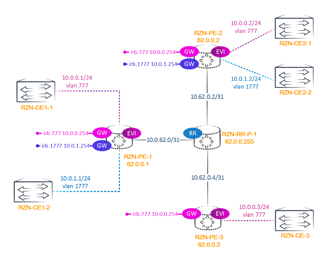
Our scheme is as follows:

As you understand, we have three PE routers, one P-router, it is also a router reflector, and three CE routers. All addressing for convenience is shown in the diagram.
Juniper allows us to configure routing-instance for EVPN in two ways - the first is an instance with type EVPN — the simplest, and the second, an instance with type virtual-switch. Personally, I prefer the second option, since it is more flexible, but for clarity in our lab we will use both methods. However, the differences between these two methods are not only in the configuration.
VLAN Based Service - This type of use of EVPN is good because the bridge domains are completely isolated from each other. But for each vlan you have to do a new routing instance. In such a scenario, traffic between PE routers can go either with a vlan tag or untagged. JunOS defaults to send tagged traffic with the original tag (unless, of course, any tag rewriting rules are configured on the interface).
The configuration of the routing instance with the EVPN type looks like this:
bormoglotx@RZN-PE-3> show configuration routing-instances RZN-VPN-1 instance-type evpn; vlan-id 777; interface ge-0/0/2.200; interface ge-0/0/2.777; routing-interface irb.777; route-distinguisher 62.0.0.3:1; vrf-import VPN-1-IMPORT; vrf-export VPN-1-EXPORT; protocols { evpn { interface ge-0/0/2.777; } } bormoglotx@RZN-PE-3> show configuration interfaces ge-0/0/2 description "link to RZN-CE3-SW1"; flexible-vlan-tagging; encapsulation flexible-ethernet-services; mac 50:01:00:03:00:04; unit 777 { encapsulation vlan-bridge; vlan-id 777; family bridge; } In an EVPN type instance configuration, you should pay attention to this line:
bormoglotx@RZN-PE-3> show configuration routing-instances RZN-VPN-1 | match vlan vlan-id 777; This value determines which tag is used for normalization. That is, if in addition to Vlan 777, Vlan 200 is also connected to this EVPN instance (as in the config shown above), when receiving a packet with a tag 200, the PE router will remove this tag (tag 200) and hang a new one - 777. At the reception PE will act in reverse order - tag 777 will be removed and tag 200 will be hung when sent to the interface in the direction of the CE router, in our case to the ge-0/0 / 2.200 interface (see the configuration above, this CE is not shown in the diagrams ).
This is the minimum configuration that will allow EVPN to work (do not forget about the basic network configuration - IGP, MPLS, etc., which is not represented here). As you can see, we specify RD and RT , since BGP is used for signaling. Everything is as usual - RD makes our route unique, and RT is used to filter routes. The import and export policies on all PE routers are the same, but for those who are interested in their configuration, I will bring it under the spoiler:
Policy configuration
bormoglotx@RZN-PE-3> show configuration policy-options policy-statement VPN-1-IMPORT term DEFAULT-IMPORT { from { protocol bgp; community VPN-1; } then accept; } term REJECT { then reject; } bormoglotx@RZN-PE-3> show configuration policy-options policy-statement VPN-1-EXPORT term DEFAULT { then { community + VPN-1; accept; } } term REJECT { then reject; } bormoglotx@RZN-PE-3> show configuration policy-options community VPN-1 members target:6262:777; VLAN Aware Service - in this case we do only one routing instance with the type virtual switch and add bridge domains to it. If the client has 30 vlans, we do not need to fence the config into hundreds of lines, making an instance for each vlan - just add 30 bridge-domains to the instance created for the client. In this case, the presence of the vlan tag, according to the RFC, is mandatory.
The instance configuration with the type virtual-switch has something like this:
bormoglotx@RZN-PE-1> show configuration routing-instances RZN-VPN-1 instance-type virtual-switch; interface ge-0/0/2.0; route-distinguisher 62.0.0.1:1; vrf-import VPN-1-IMPORT; vrf-export VPN-1-EXPORT; protocols { evpn { extended-vlan-list 777; } } bridge-domains { VLAN-777 { vlan-id 777; } } bormoglotx@RZN-PE-1> show configuration interfaces ge-0/0/2 description "link to RZN-CE1-SW1"; flexible-vlan-tagging; encapsulation flexible-ethernet-services; mac 50:01:00:01:00:04; unit 0 { family bridge { interface-mode trunk; vlan-id-list 777; } } There should be no problems when using EVPN on the one hand, and there should be no virtual switch on the other (if you do everything as it should be), since JunOS from the EVPN instance sends tagged traffic with the original tag. In any case, during the testing I did not find any problems. But there is one nuance. It should be borne in mind that normalization can play a cruel joke with you if you start using different types of instances in the same EVPN domain without dividing the bridge across the bridge domains. For example, on one PE router to the EVPN type instance you add two vlans: 777 and 1777, and for normalization you use the vlan 777. From the other end you will have a virtual switch with two bridge domains - vlan 777 and vlan 1777. As a result, we get: the packet arrives from CE in vlan 1777, the vlan happens to normalize to 777 and the virtual switch instantiates the packet arrives in vlan 777. And the destination host is in vlan 1777, that is, in another bridge domain. As a result, you do not have connectivity between hosts in the same vlan. Or another scenario - in the same bridge domain, you configured different tags for normalization. In this scenario, you also will not have connectivity (it will not exist at all), since with PE1 the packet will fly away, for example, with the normal tag 777, and on PE2 the normal tag will be 1777. As a result, PE2 will simply discard the packets with the wrong vlan number.
Type 3 route
At this point in time, no exchange of packets between CE routers has been done (of course, CDP , LLDP and other joys are disabled, so that something extra is not flown into the network), so none of the PE routers have learned a single MAC address. This can be checked:
bormoglotx@RZN-PE-1> show evpn instance RZN-VPN-1 brief Intfs IRB intfs MH MAC addresses Instance Total Up Total Up Nbrs ESIs Local Remote RZN-VPN-1 1 1 0 0 2 0 0 0 From this conclusion, we can learn that there is only 1 interface in this routing-instance and it is active, we do not have IRB interfaces (more about them later). We see two neighbors (according to our scheme, this is PE2 and PE3), and also that we have not yet studied any MAC addresses (local is MAC addresses local to this PE router, and remote are MAC addresses received from neighboring PE routers).
Now let's see what routes we have in the routing table of this routing-instance:
bormoglotx@RZN-PE-1> show route table RZN-VPN-1.evpn.0 RZN-VPN-1.evpn.0: 3 destinations, 3 routes (3 active, 0 holddown, 0 hidden) + = Active Route, - = Last Active, * = Both 3:62.0.0.1:1::777::62.0.0.1/304 *[EVPN/170] 01:33:42 Indirect 3:62.0.0.2:1::777::62.0.0.2/304 *[BGP/170] 01:10:22, localpref 100, from 62.0.0.255 AS path: I, validation-state: unverified > to 10.62.0.1 via ge-0/0/0.0, Push 299808 3:62.0.0.3:1::777::62.0.0.3/304 *[BGP/170] 01:10:01, localpref 100, from 62.0.0.255 AS path: I, validation-state: unverified > to 10.62.0.1 via ge-0/0/0.0, Push 299776 We have only three routes, with the first local one for PE1. What are these routes and why are they needed? Let's figure it out. There are only 5 types of routes in EVPN:
- 1 - Ethernet Auto-Discovery (AD) route
- 2 - MAC / IP Advertisement route
- 3 - Inclusive Multicast Ethernet Tag route
- 4 - Ethernet Segment route
- 5 - IP Prefix Route *
Note: the route of the 5th type is currently not yet approved in the RFC statute, and so far it has been described only in the draft and therefore we will not consider it in this article.
In the above output, we see that the first digit in the route is 3 , which means it is Inclusive Multicast Ethernet Tag route . This route is generated by each PE router and is used to receive and send BUM traffic. The route consists of the following fields:

RD - I think everyone understands what it is, in the announcement below it is : 62.0.0.3: 1:
Ethernet Tag ID is the Vlan number, in our case : 777:
IP Address Length - the length of the IP address specified in the next field (this value is not shown on Juniper equipment)
Originating Router's IP Address - The IP address of the originator of the route, usually a loopback PE router. In our case it is : 62.0.0.3 .
Note: / 304 is the prefix length, Juniper automatically adds it to all EVPN routes, in fact, does not carry a semantic load. As written on the Juniper website, this value means the maximum length of the route and allows you to use this feature when searching for routes using regular expressions. Well, we take into account for the future.
3:62.0.0.3:1::777::62.0.0.3/304 (1 entry, 1 announced) *BGP Preference: 170/-101 Route Distinguisher: 62.0.0.3:1 PMSI: Flags 0x0: Label 299904: Type INGRESS-REPLICATION 62.0.0.3 Next hop type: Indirect Address: 0x95ca3d4 Next-hop reference count: 2 Source: 62.0.0.255 Protocol next hop: 62.0.0.3 Indirect next hop: 0x2 no-forward INH Session ID: 0x0 State: <Secondary Active Int Ext> Local AS: 6262 Peer AS: 6262 Age: 1:16:02 Metric2: 1 Validation State: unverified Task: BGP_6262.62.0.0.255+179 Announcement bits (1): 0-RZN-VPN-1-evpn AS path: I (Originator) Cluster list: 62.0.0.255 Originator ID: 62.0.0.3 Communities: target:6262:777 Import Accepted Localpref: 100 Router ID: 62.0.0.255 Primary Routing Table bgp.evpn.0 If you look at the route more closely, we see the following line:
PMSI: Flags 0x0: Label 299904: Type INGRESS-REPLICATION 62.0.0.3 PMSI stands for Provider Multicast Service Interface, and this is nothing more than Point-to-Multipoint LSPs. In this article we will not consider how P2MP LSP works, since this is a very large and complex topic, but as you can see, EVPN uses p2mp LSP functionality to forward BUM traffic. PE3 generated a 299904 label that other PE routers can use to send BUM traffic to PE3.
The type 3 route is generated for each vlan separately, which is what the words Ethernet Tag say in its name. If you have two bridge-domains (for example, vlan 777 and vlan 1777), then the PE router will generate two type 3 routes — one for each vlan (bridge-domain).
We found out that at the initial moment of time there are only type 3 routes in the EVPN routing table, so that PE routers know what label to send broadcast packets to remote PE routers.
Type 2 Route
Now run the ping between CE1 and CE2:
RZN-CE1-SW1#ping 10.0.0.2 Type escape sequence to abort. Sending 5, 100-byte ICMP Echos to 10.0.0.2, timeout is 2 seconds: .!!!! Success rate is 80 percent (4/5), round-trip min/avg/max = 7/8/11 ms One packet was lost because CE1 made an ARP request for resolving the address 10.0.0.2. Now let's see if the addresses appear in the MAC table:
bormoglotx@RZN-PE-1> show evpn instance RZN-VPN-1 brief Intfs IRB intfs MH MAC addresses Instance Total Up Total Up Nbrs ESIs Local Remote RZN-VPN-1 1 1 0 0 2 0 1 1 Two MAC addresses appeared at once: one local for PE1 (address CE1) and one MAC received from PE2 (address CE2):
bormoglotx@RZN-PE-1> show route table RZN-VPN-1.evpn.0 RZN-VPN-1.evpn.0: 5 destinations, 5 routes (5 active, 0 holddown, 0 hidden) + = Active Route, - = Last Active, * = Both 2:62.0.0.1:1::777::aa:bb:cc:00:06:00/304 *[EVPN/170] 00:05:23 Indirect 2:62.0.0.2:1::777::aa:bb:cc:00:07:00/304 *[BGP/170] 00:05:23, localpref 100, from 62.0.0.255 AS path: I, validation-state: unverified > to 10.62.0.1 via ge-0/0/0.0, Push 299808 Now we have two new routes in the table (just in route table 5, type 3 routes are not shown to reduce the output). Routes are type 2 - MAC / IP Advertisement route. This route is as follows:

RD - Route Distinguisher, where without it, in our case it is : 62.0.0.2: 1 ;
Ethernet Segment Identifier - identifier of ESI , we will talk about it later. JunOS shows this value only for detail or extensive outputs, in our route it is zero: ESI: 00: 00: 00: 00: 00: 00: 00: 00: 00: 00: 00 ;
Ethernet Tag ID - Vlan number : 777 ;
MAC Address Length - the length of the MAC address, in fact, always 48 bits, and JunOS does not output this value;
MAC Address - the MAC address itself: aa: bb: cc: 00: 07: 00 ;
IP Address Length is the length of the IP address, is 32 bits for IPv4, and 128 for IPv6. This field is optional and may not contain any values (all zeros). JunOS does not display this value.
IP Address - the address itself, it is not represented in the output below. The field is filled optionally.
MPLS Label1 | 2 - the label itself, JunOS shows it only when it is detailed or extensive output.
2:62.0.0.2:1::777::aa:bb:cc:00:07:00/304 (1 entry, 1 announced) *BGP Preference: 170/-101 Route Distinguisher: 62.0.0.2:1 Next hop type: Indirect Address: 0x95c9f90 Next-hop reference count: 4 Source: 62.0.0.255 Protocol next hop: 62.0.0.2 Indirect next hop: 0x2 no-forward INH Session ID: 0x0 State: <Secondary Active Int Ext> Local AS: 6262 Peer AS: 6262 Age: 26 Metric2: 1 Validation State: unverified Task: BGP_6262.62.0.0.255+179 Announcement bits (1): 0-RZN-VPN-1-evpn AS path: I (Originator) Cluster list: 62.0.0.255 Originator ID: 62.0.0.2 Communities: target:6262:777 Import Accepted Route Label: 300272 ESI: 00:00:00:00:00:00:00:00:00:00 Localpref: 100 Router ID: 62.0.0.255 Primary Routing Table bgp.evpn.0 As I wrote earlier, EVPN uses MAC addresses as routing addresses. From the announcement from PE2, PE1 now knows that in order to get to the MAC address aa: bb: cc: 00: 07: 00 in vlan 777 (note that it is in 777 vlan, since the same MAC address is maybe in different vlans, and these will be different routes), you need to hang two tags on the packet: 300272 (VPN) and a transport label up to 62.0.0.2.
Note: in addition to the well-known Route Distinguisher, Protocol next hop, and so on fields, we see the ESI field, which is set to zero in this announcement. This field is very important when using multihomed sites, and we will return to it a little later, in this scenario it does not matter.
Like L3VPN, EVPN can generate per-mac, per-next-hop and per-instance tags:
per-mac - a separate label is generated for each mac address. As you understand this kind of label distribution is too wasteful;
per-next-hop - probably more accurate is to say per-CE or per-AC, that is, the same label is generated only for MAC addresses that are located behind the same Attachment Circuit (that is, if to the same PE router in the same routing-instance has two CE routers connected, then for MAC addresses learned from CE1, PE router will generate one label, and for MAC addresses learned from CE2 - another)
per-instance - one label is generated for the entire routing-instance, that is, all routes will have the same label. In JunOS, you can see this label when viewing the EVPN instance in extensive mode.
Learning MAC Addresses
Now look at the MAC table on PE1:
bormoglotx@RZN-PE-1> show bridge mac-table MAC flags (S -static MAC, D -dynamic MAC, L -locally learned, C -Control MAC SE -Statistics enabled, NM -Non configured MAC, R -Remote PE MAC) Routing instance : RZN-VPN-1 Bridging domain : VLAN-777, VLAN : 777 MAC MAC Logical NH RTR address flags interface Index ID aa:bb:cc:00:06:00 D ge-0/0/2.0 aa:bb:cc:00:07:00 DC 1048575 1048575 The flag column tells us how this address was learned: the MAC address aa: bb: cc: 00: 06: 00 has only the D flag, which means that this Mac is dynamically learned (in the standard way through the data plane) and as we don’t see any more flags, we can safely say that this MAC has been learned from a locally connected CE router. But the MAC address aa: bb: cc: 00: 07: 00 has two flags - DC. We already know what the first flag means, but the C flag indicates that this address was learned through the control plane.
If we look at the table of MAC addresses on PE3, we will see that all the addresses are learned by the PE router via the control plane, and there is not a single local MAC address:
bormoglotx@RZN-PE-3> show evpn mac-table MAC flags (S -static MAC, D -dynamic MAC, L -locally learned, C -Control MAC SE -Statistics enabled, NM -Non configured MAC, R -Remote PE MAC) Routing instance : RZN-VPN-1 Bridging domain : __RZN-VPN-1__, VLAN : 777 MAC MAC Logical NH RTR address flags interface Index ID aa:bb:cc:00:06:00 DC 1048574 1048574 aa:bb:cc:00:07:00 DC 1048575 1048575 Note: if you noticed, in one case I used the show bridge command mac-table, and in the second I showed evpn mac-table command. This is due to the fact that on different PE routers the routing instance is configured differently - in the first case, virtual-swicth, in the second EVPN.
There are no locally learned MAC addresses on PE3, as there has not yet been traffic from CE3. Let's correct this situation by running the ping to CE3, and once again look at this table:
RZN-CE1-SW1#ping 10.0.0.3 Type escape sequence to abort. Sending 5, 100-byte ICMP Echos to 10.0.0.3, timeout is 2 seconds: .!!!! Success rate is 80 percent (4/5), round-trip min/avg/max = 7/10/13 ms bormoglotx@RZN-PE-3> show evpn mac-table MAC flags (S -static MAC, D -dynamic MAC, L -locally learned, C -Control MAC SE -Statistics enabled, NM -Non configured MAC, R -Remote PE MAC) Routing instance : RZN-VPN-1 Bridging domain : __RZN-VPN-1__, VLAN : 777 MAC MAC Logical NH RTR address flags interface Index ID aa:bb:cc:00:05:00 D ge-0/0/2.777 aa:bb:cc:00:06:00 DC 1048574 1048574 aa:bb:cc:00:07:00 DC 1048575 1048575 As you can see, the CE3 MAC address has now appeared on PE3, learned through the data plane.
Like an ordinary switch, addresses in the EVPN MAC table have a certain “expiration date”, by default this period is 300 seconds. If during this time this MAC was inactive and not updated, the route is removed from the table. It seems that everything is simple - the timer has worked - the MAC has been deleted. But everything is not as simple as it seems. Let's look at how this happens.
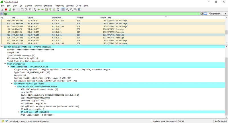
So, PE3 learned the MAC address of CE3 and sent it in BGP announcement to the other PE routers. Suppose that the recording was not updated within 300 seconds. Then PE3 must remove this MAC address from the table, which it does. But we remember that PE3 sent information to all its neighbors that this MAC address is located behind it. What if this host has moved or is it already turned off? What then? Will the other PE routers send packets for CE3 to PE3, like in a black hole? Of course not. The fact is that if the PE router removes the local MAC address from the table, then it sends a BGP Withdrawn message, which causes other PE routers to delete this route, and therefore the MAC address, from their tables. Let's check it out.
The first screen shows BGP UPDATE Message, which announces the MAC address aa: bb: cc: 00: 07: 00 (the pictures are clickable):

After 300 seconds, we see another BGP UPDATE Message, which is a Withdrawn message, canceling the route to the previously specified MAC address:
In addition to MAC aging time, EVPN has a mechanism for signaling the change of the MAC address. When a Gratuitous ARP is received from the PE router's CE, BGP Update is generated, which contains a withdrawn message indicating the old MAC address and the announcement of the new MAC address.
But besides the MAC address, the MAC / IP Advertisement route can optionally also contain the IP address of the host. Add the IRB routing interface to our EVPN and see which route appeared:
bormoglotx@RZN-PE-1> show configuration interfaces irb.777 family inet { address 10.0.0.254/24; } mac 02:00:00:00:00:02; bormoglotx@RZN-PE-1> *2:62.0.0.1:1::777::02* show route table RZN-VPN-1.evpn.0 match-prefix RZN-VPN-1.evpn.0: 18 destinations, 18 routes (18 active, 0 holddown, 0 hidden) + = Active Route, - = Last Active, * = Both 2:62.0.0.1:1::777::02:00:00:00:00:02/304 *[EVPN/170] 14:17:31 Indirect 2:62.0.0.1:1::777::02:00:00:00:00:02::10.0.0.254/304 *[EVPN/170] 14:17:31 Indirect There are two new routes, the first is only the irb.777 MAC address, and here is the second MAC + IP. Mac + IP announcement has the form of ARP records, all PE routers participating in the same EVPN domain synchronize their ARP records, which allows reducing the number of flood of broadcasting ARP requests across the provider's network.
Now we will take a closer look at the route:
bormoglotx@RZN-PE-1> show route table RZN-VPN-1.evpn.0 match-prefix *2:62.0.0.1:1::777::02* detail RZN-VPN-1.evpn.0: 18 destinations, 18 routes (18 active, 0 holddown, 0 hidden) 2:62.0.0.1:1::777::02:00:00:00:00:02/304 (1 entry, 1 announced) *EVPN Preference: 170 Next hop type: Indirect Address: 0x940d804 Next-hop reference count: 7 Protocol next hop: 62.0.0.1 Indirect next hop: 0x0 - INH Session ID: 0x0 State: <Active Int Ext> Age: 14:21:34 Validation State: unverified Task: RZN-VPN-1-evpn Announcement bits (1): 1-BGP_RT_Background AS path: I Communities: evpn-default-gateway Route Label: 300144 ESI: 00:00:00:00:00:00:00:00:00:00 In this route, a new extended community evpn-default-gateway appeared. This is how routes that are the main gateway for the routing-instance are marked. This route will be generated for each vlan separately.
Why are two routes generated? The fact is that the first route, in which only the MAC address is specified, is used exclusively for switching in the bringe domain, while the MAC + IP route is already used for routing and is essentially an arp entry. I'll run a bit ahead and write that routes to hosts will also be generated in the same way when traffic moves to other vlans or to an external network (we will look at this later when adding another vlan to the scheme).
Type 1 Route
So far, we have ignored type 1 and type 4 routes. These routes are used for multihomed sites.
Note: due to too much of the article, we will not dive deep into the work of EVPN with multihomed sites. If someone is interested - write in the comments - I will write a separate article on this topic.
Type 1 route is as follows:

1:62.0.0.2:0::112233445566778899aa::0/304 *[BGP/170] 00:00:56, localpref 100, from 62.0.0.255 AS path: I, validation-state: unverified > to 10.62.0.1 via ge-0/0/0.0, Push 299792 This route does not carry information about MAC-addresses, but has a very wide application, such as:
- Automatic search for PE routers to which the same CE router is connected
- ESI announcement tags
- Announcement of mass cancellation of learned MAC addresses
- Announcement Aliasing tags
Type 1 route can be announced per- EVI or per-ESI. The first announcement is used when announcing the Aliasing label, the second - to enable the mass cancellation of the announced MAC addresses of any ethernet segment.
Let's look at the above described function of this route in more detail.
Auto search for multihomed PE and ESI label
Unlike VPLS, the automatic discovery of PE routers connected to the same CE router (multihomed sites) is enabled in EVPN. In terms of EVPN, the PE <-> CE junction is called Ethernet Segment. Each segment is assigned an ESI (Ethernet Segment Identifier, a number of 80 bits in size recorded in 10 groups of 8 bits in a group). For single-homed sites, this identifier does not matter and is therefore automatically assigned and equal to 0. But for multihomed sites, this identifier is very important and must be unique for the entire EVPN domain (since the number of possible ESI combinations is very large and equal to 2 ^ 80) .ESs connected to the same CE router must have the same ESI . Two values from the entire range are reserved and cannot be set administratively - these are all zeros (used as an identifier for non-multihoming segments) and all F.
In the above output, a magic set of letters and numbers : 112233445566778899aa: is nothing more than ESI configured network administrator on the physical interface:
bormoglotx@RZN-PE-2> show configuration interfaces ge-0/0/4 description "link to RZN-MULTI-SW-1"; flexible-vlan-tagging; encapsulation flexible-ethernet-services; esi { 11:22:33:44:55:66:77:88:99:aa; single-active; } mac 50:01:00:02:00:06; unit 111 { encapsulation vlan-bridge; vlan-id 111; family bridge; } This route, in addition to ESI, is very important, which is represented in the form of an extended community: esi-label. It looks like this:
bormoglotx@RZN-PE-2> show route table RZN-VPN-3.evpn.0 match-prefix *1:62* detail RZN-VPN-3.evpn.0: 6 destinations, 6 routes (6 active, 0 holddown, 0 hidden) 1:62.0.0.1:0::112233445566778899aa::0/304 (1 entry, 1 announced) *BGP Preference: 170/-101 Route Distinguisher: 62.0.0.1:0 Next hop type: Indirect Address: 0x95c0f28 Next-hop reference count: 20 Source: 62.0.0.255 Protocol next hop: 62.0.0.1 Indirect next hop: 0x2 no-forward INH Session ID: 0x0 State: <Secondary Active Int Ext> Local AS: 6262 Peer AS: 6262 Age: 2:50 Metric2: 1 Validation State: unverified Task: BGP_6262.62.0.0.255+179 Announcement bits (1): 0-RZN-VPN-3-evpn AS path: I (Originator) Cluster list: 62.0.0.255 Originator ID: 62.0.0.1 Communities: target:6262:111 esi-label:00049660(label 300640) <<<<<<community Import Accepted Localpref: 100 Router ID: 62.0.0.255 Primary Routing Table bgp.evpn.0 Since this route has a native extended community, typical for this EVPN-domain, all PE routers in the evpn-domain import this route into the routing table of the corresponding EVPN instance:
bormoglotx@RZN-PE-3> show route table RZN-VPN-3.evpn.0 match-prefix *1:62* detail | match esi Communities: target:6262:111 esi-label:00049660(label 300640) Communities: target:6262:111 esi-label:00049680(label 300672) Why is it needed?Consider the following scheme:

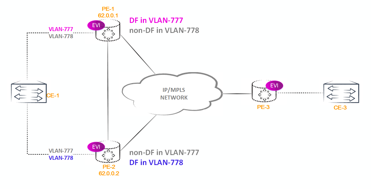
In this scenario, we have a potential L2 loop, because if BUM traffic from CE1 falls on PE2, it will be sent to all other PE routers, including PE1. PE1 also has a link to CE1, from which the BUM traffic was received . And if PE1 sends a packet to CE1, then we get a loop at level 2, and as you know, there is no ttl field in the L2 header. The situation, to put it mildly, will be unpleasant. How to deal with it?In EVPN, a Designated Forwarder (DF) selection is automatically used for this purpose. How it is chosen, we will consider later, but for now let's talk about his appointment.
DF has the exclusive right to send broadcast frames towards the CE of the router located on the ethernet segment for which this PE router is DF. All other non-DF routers BUM traffic towards the CE router does not send.
We can have two scenarios: when using Single-Active mode and when using Active-Active mode (All-Active).
As you might guess, in Single-Active mode, we have only one shoulder, the second is in reserve. In the case of the fall of the main shoulder, the traffic goes to the backup. It is possible to use one shoulder to transmit traffic in one vlan, and the second in the second, but traffic cannot go along both shoulders in one vlan (it should not be more precise - if not, then write in support, apparently you found a bug, or more likely, from the engineer who collected the circuit, hand curves).
In Active-Active or All-Active mode, all links from CE to PE work, for which the MC-LAG is built . The principle of operation of the MC-LAG technology in this article will not be considered: it is understood that the reader has already studied this topic.
In the first case, everything is simple - DF is selected, and all traffic, including BUMtraffic, only he forwards. At the same time, there is no ESI label in the announcement (in any case it is not on Juniper equipment), although according to the RFC, even in Single-Active mode, it is recommended to use this label so that in case of an error in the DF selection mechanism (when both PE routers suddenly consider themselves DF) did not form a loop.
During normal operation of the DF selection mechanism, one shoulder is simply blocked, which means that the PE router does not examine the MAC address via a blocked link, and therefore does not announce anything to other PE routers. But, even if some BUM traffic arrives on this router , it will just be dropped.

In the second case, a little harder. There is also selected DF, which has the right to sendBUM traffic in the direction of the CE router - that is, problems with traffic going to the CE router, no. Problems may arise when sending BUM traffic from the CE router. Since the CE router has absolutely no difference who of the PE DF routers (more precisely, the CE router thinks that it is simply connected to another switch with an aggregated interface), the following situation is possible. Suppose that a broadcast packet from CE1 arrives on PE1, which is not a DF. PE1 receives the packet and sends it to all other PE routers, including PE2. PE2, being the DF router for this segment, will forward BUMTraffic back to CE router. Yes, got a loop. This is where the ESI label comes in handy. The fact is that when sending a packet to PE2, PE1 places two labels: the ESI label (bottom of the labels) and the Inclusive Multicast label. PE2 receives the packet, removes the top label and detects the ESI label, this tells the router that it does not need to flood the packet in the direction of CE1, since the traffic from this segment has flown. But why then send this packet to PE2? The fact is that PE2, in addition to CE1, from which this traffic was received, can be connected to other CE routers that may be interested in this traffic.

Abbreviations in the diagram:
IM - Inclusive Multicast label
ESI - ESI label
TL - Transport MPLS label
: PE1 PE2 , PE1 PE2 . , .
MAC Mass Withdrawal
This function is intended for those cases when one of the links with which the multihomed CE router is connected falls off. Since in the case of the Active-Active mode, the traffic from the CE of the router is balanced, the MAC addresses will also be learned from both PE routers. If one of the links falls, the PE router should cancel all routes of this segment that were sent to them. Imagine that there are 1000 or more of them, then we will get a high utilization of the processor by a sharp burst of BGP messages, which can badly affect the entire control-plane. And in time, processing a large number of Withdrawn messages is not so simple. Therefore, the PE router sends Withdrawn a message about canceling a previously sent type 1 route generated per-ESI (more on that later). Having received this message,other PE routers can either clear all MAC label matches that are associated with a given segment (ES), or if there is another router in this segment that is able to forward traffic, then use the routes received from it (that is, in fact, change the protocol next -hop) If the last router in the segment has died, then clear the MAC address table associated with the segment.
As you understand, it is necessary to quickly switch from reserve to backup.
Aliasing label
Again, this feature concerns the multihoming CE. Traffic from the CE router in All-Active mode must be balanced between all links. Since balancing is performed according to some algorithm, known only to the CE router and its developer, it is possible that the multihoming CE router will send all outgoing traffic only through one interface. As a result, type 2 routes will be sent from only one PE router, suppose that only from PE1:

Since other routers will not know how to get to the specified segment through PE2, traffic will not flow through it, which will cause a simple one of the shoulders between the PE and CE routers. To do this, each PE router announces announces an Aliasing label for its ethernet segment. Since the remaining PE routers receive type 1 routes, they see that PE1 and PE2 have links in the same ES and work in All-Active mode. Using the received aliasing tag, other PE routers can send packets to the CE router and through PE1 and PE2, visiting the packet that goes through PE2 instead of the VPN tag — the Aliasing tag received from PE2 in a type 1 route generated by per- EVI .

Abbreviations on the diagram:
AL - Aliasing label
EVPN - EVPN label
TL - Transport MPLS label
In routes of type 1 there is a flag that is responsible for informing other PE routers of the mode in which the PE router is operating in this ethernet segment — Single-Active or All-Active. This flag is located in the extended community, added to the announcement of the type 1 route. If the flag is raised, the router operates in the Single-Active mode (the flag is called the Single-Active flag), if the flag is not raised, the router operates in All- Active mode. Below is an example of a route in which the flag is raised and the label is missing:
bormoglotx@RZN-PE-1> show route advertising-protocol bgp 62.0.0.255 table __default_evpn__.evpn.0 detail match-prefix *112233445566778899aa::* __default_evpn__.evpn.0: 9 destinations, 9 routes (9 active, 0 holddown, 0 hidden) * 1:62.0.0.1:0::112233445566778899aa::0/304 (1 entry, 1 announced) BGP group RR-NODES type Internal Route Distinguisher: 62.0.0.1:0 Nexthop: Self Flags: Nexthop Change Localpref: 100 AS path: [6262] I Communities: target:6262:111 esi-label:100000(label 0) But the route is already marked and not raised by the Single-Active flag:
bormoglotx@RZN-PE-1> show route advertising-protocol bgp 62.0.0.255 table __default_evpn__.evpn.0 detail match-prefix *62000000000000000001::* __default_evpn__.evpn.0: 9 destinations, 9 routes (9 active, 0 holddown, 0 hidden) * 1:62.0.0.1:0::62000000000000000001::0/304 (1 entry, 1 announced) BGP group RR-NODES type Internal Route Distinguisher: 62.0.0.1:0 Nexthop: Self Flags: Nexthop Change Localpref: 100 AS path: [6262] I Communities: target:100:100 esi-label:000493a0(label 299936) Type 4 route
Now let's sort the route of type 4. This route is needed to select the DF, the purpose of which I wrote earlier. This route is as follows:

bormoglotx@RZN-PE-2> show route table bgp.evpn.0 match-prefix *4:6* bgp.evpn.0: 11 destinations, 11 routes (11 active, 0 holddown, 0 hidden) + = Active Route, - = Last Active, * = Both 4:62.0.0.1:0::112233445566778899aa:62.0.0.1/304 *[BGP/170] 01:07:57, localpref 100, from 62.0.0.255 AS path: I, validation-state: unverified > to 10.62.0.3 via ge-0/0/0.0, Push 299808 It is noteworthy that this route does not carry the community, which is configured for export from the routing-instance:
bormoglotx@RZN-PE-2> show route table bgp.evpn.0 match-prefix *4:6* detail bgp.evpn.0: 11 destinations, 11 routes (11 active, 0 holddown, 0 hidden) 4:62.0.0.1:0::112233445566778899aa:62.0.0.1/304 (1 entry, 0 announced) *BGP Preference: 170/-101 Route Distinguisher: 62.0.0.1:0 Next hop type: Indirect Address: 0x95c1954 Next-hop reference count: 14 Source: 62.0.0.255 Protocol next hop: 62.0.0.1 Indirect next hop: 0x2 no-forward INH Session ID: 0x0 State: <Active Int Ext> Local AS: 6262 Peer AS: 6262 Age: 1:07:59 Metric2: 1 Validation State: unverified Task: BGP_6262.62.0.0.255+51796 AS path: I (Originator) Cluster list: 62.0.0.255 Originator ID: 62.0.0.1 Communities: es-import-target:33-44-55-66-77-88 Import Accepted Localpref: 100 Router ID: 62.0.0.255 Secondary Tables: __default_evpn__.evpn.0 These routes use the new community: es-import-target: XX-XX-XX-XX-XX-XX . The community itself is generated from ESI. To do this, 48 bits are taken from the identifier, as shown below:
ESI:
11:22: 33: 44: 55: 66: 77: 88 : 99: aa Community
generated:
Communities: es-import-target: 33-44-55 -66-77-88
Only PE routers that have the same ESI (more precisely, the same bits from 16 to 64 in the identifier) import this route. As you can see, in the announcement there is no RT specified for import or export in the routing instance. That is, type 4 routes are not visible in the routing table of EVPN itself. They can be viewed only in the bgp.evpn.0 and __default_evpn __. Evpn.0 tables.
If the other PE router has ESI , for example aaaa334455667788aaaa, then, as it is not difficult to guess, their community will be the same, which means the route will also be imported. But do not panic, everything is already stolen to us: the full identifier of the ESI is indicated in the body of the route itself and this route will be imported but ignored. Like RT, the es-import-target is intended only for route filtering. Below is the type 4 route and its community itself:
bormoglotx@RZN-PE-1> show route table bgp.evpn.0 match-prefix *4:62* detail | match "comm|\/304" 4:62.0.0.2:0::112233445566778899aa:62.0.0.2/304 (1 entry, 0 announced) Communities: es-import-target:33-44-55-66-77-88 An interesting case is this config:
bormoglotx@RZN-PE-1> show configuration interfaces ae1 | match esi | display set set interfaces ae1 esi 62:00:00:00:00:00:00:00:00:01 set interfaces ae1 esi all-active I think you already guessed that we get in the announcement of an extended community consisting of all zeros:
bormoglotx@RZN-PE-1> show route advertising-protocol bgp 62.0.0.255 table __default_evpn__.evpn.0 detail match-prefix *62000000000000000001:6* __default_evpn__.evpn.0: 9 destinations, 9 routes (9 active, 0 holddown, 0 hidden) * 4:62.0.0.1:0::62000000000000000001:62.0.0.1/304 (1 entry, 1 announced) BGP group RR-NODES type Internal Route Distinguisher: 62.0.0.1:0 Nexthop: Self Flags: Nexthop Change Localpref: 100 AS path: [6262] I Communities: es-import-target:0-0-0-0-0-0 Do not assume that because of this, everything will break. Even with such a community everything will work, but if you have, for example, an ESI in the range xx: xx: 00: 00: 00: 00: 00: 00: 00: 01-xx: xx: 00: 00: 00 : 00: 00: 00: 99: 99, then all type 4 routes will have the same community, which means that PE routers will accept and install all type 4 routes in the routing tables, even if they do not need them. But I think that you shouldn’t sweat about it, plus / minus 100 weather routes will not do (why they won’t, you will understand when you finish the article to the end).
I don’t know if the reader noticed, but on routes like 1 and 4 the RD looks a bit strange. For example, route type 2 from PE2:
2:62.0.0.2:1::777::aa:bb:cc:00:07:00/304 *[BGP/170] 00:00:18, localpref 100, from 62.0.0.255 AS path: I, validation-state: unverified > to 10.62.0.1 via ge-0/0/0.0, Push 299792 But the route type 1 from the same PE2:
1:62.0.0.2:0::112233445566778899aa::0/304 *[BGP/170] 00:00:56, localpref 100, from 62.0.0.255 AS path: I, validation-state: unverified > to 10.62.0.1 via ge-0/0/0.0, Push 299792 From PE2, route 1 of type 1 has RD 62.0.0.2 , although routes from type 2 or 3 of this same PE2 come from RD 62.0.0.2:1 , which is configured in routing instance. What happens with RD? To test this phenomenon, we create two routing instances with EVPN type and assign them completely different RDs:
bormoglotx@RZN-PE-1> show configuration routing-instances RZN-VPN-3 | match route route-distinguisher 62.0.0.1:3; bormoglotx@RZN-PE-1> show configuration routing-instances RZN-VPN-4 | match route route-distinguisher 9999:99; Now let's see how the RD type 1 route will be announced:
bormoglotx@RZN-PE-1> show route advertising-protocol bgp 62.0.0.255 | match "1:6" 1:62.0.0.1:0::112233445566778899aa::0/304 1:62.0.0.1:0::aaaa334455667788aaaa::0/304 RD in the route does not match the configured configuration on either RZN-VPN-3 or RZN-VPN-4. Where does this RD come from? JunOS automatically generates it from a router-id or loopback address. And the first value has priority. For example, we now have a router-id:
bormoglotx@RZN-PE-1> show configuration routing-options router-id router-id 62.0.0.1; And this value is taken as the first part of the RD, and the second is set to zero in our case. Let's remember the router id:
bormoglotx@RZN-PE-1> show configuration routing-options router-id router-id 62.62.62.62; We look, what routes are given now:
bormoglotx@RZN-PE-1> show route advertising-protocol bgp 62.0.0.255 | match "1:6" 1:62.62.62.62:0::112233445566778899aa::0/304 1:62.62.62.62:0::aaaa334455667788aaaa::0/304 As you can see JunOS itself generated RD. What happens if we do not specify the router-id? Let's check. But let's complicate the task by hanging a couple of addresses on a loopback:
bormoglotx@RZN-PE-1> show configuration interfaces lo0 description "BGP & MPLS router-id"; unit 0 { family inet { address 10.1.1.1/32; address 62.0.0.1/32; address 62.62.62.62/32; } family iso { address 49.0000.0620.0000.0001.00; We look now:
bormoglotx@RZN-PE-1> show route advertising-protocol bgp 62.0.0.255 | match " 1:(1|6)" 1:10.1.1.1:0::112233445566778899aa::0/304 1:10.1.1.1:0::aaaa334455667788aaaa::0/304 JunOS chose the smallest loupeback IP address and used it as a router-id. This is because this type 1 route is generated per-ESI. If the route is generated by per- EVI , then it will have a native RD instance from which this route is announced. But the type 4 route will always have a RD unique to the router, since it is always generated per-ESI.
Per-ESI route generation has some peculiarity. Since the ESI idconfigured on the physical interface, if we have for example 10 logical units (we can say vlans) on this interface and all in different EVPN instances, we will get that the same type 1 route will be generated in different instances. Why generate 10 identical routes (the difference in them will be only in RT), if you can generate only one and attach RT-ki to all instances that are interested in this route?
Let's see how this works with an example. Here is the ESI configuration on the physical interface:
bormoglotx@RZN-PE-1> show configuration interfaces ge-0/0/2 | match esi | display set set interfaces ge-0/0/2 esi 00:00:00:00:00:00:00:00:00:07 set interfaces ge-0/0/2 esi single-active This interface is used by two evpn type instances:
bormoglotx@RZN-PE-1> show configuration routing-instances | display set | match ge-0/0/2. set routing-instances RZN-VPN-1 interface ge-0/0/2.0 set routing-instances eVPN-test interface ge-0/0/2.200 Let's see which RTs correspond to these instances (I deleted the policies and prescribed RT using the vrf-target for clarity):
bormoglotx@RZN-PE-1> show configuration routing-instances RZN-VPN-1 | match target vrf-target target:62:1; bormoglotx@RZN-PE-1> show configuration routing-instances eVPN-test | match target vrf-target target:62:2; Now let's look at the route of type 1, announced on the reflector:
bormoglotx@RZN-PE-1> show route advertising-protocol bgp 62.0.0.255 table __default_evpn__.evpn.0 match-prefix *1:6*:07:* detail __default_evpn__.evpn.0: 8 destinations, 8 routes (8 active, 0 holddown, 0 hidden) * 1:62.0.0.1:0::07::0/304 (1 entry, 1 announced) BGP group RR-NODES type Internal Route Distinguisher: 62.0.0.1:0 Nexthop: Self Flags: Nexthop Change Localpref: 100 AS path: [6262] I Communities: target:62:1 target:62:2 esi-label:100000(label 0) As you can see, the route has two RTs: target: 62: 1, which corresponds to RZN-VPN-1 and target: 62: 2, corresponding to eVPN-test. This feature reduces convergence time. If this link falls off, it will fall off at all instances to which it is attached. In our case, instead of 2-x BGP Withdrawn messages, only one will fly away, but with two RTs.
Note: Type 1 and 4 routes, if we wish, we will consider the reader separately, in a separate article on EVPN multihoming.
DF selection mechanism
The DF selection mechanism allows you to select different DF for different Vlans, thus, for example, you can achieve balancing traffic between different bridge domains - traffic from different Vlans will follow different links in the direction of the CE of the router inside one EVPN instance.
The router sends a type 4 route announcement with an indication of ESI and the corresponding community and starts the DF selection timer. By default, this timer is set to 3 seconds. It can be changed, but it must be the same on all PE routers of the segment - otherwise the algorithm may not work correctly.
When the timer expires, all PE routers participating in the DF selection make a complete list of all PE routers of the segment, starting with the smallest address. Each of the PE routers in the list is assigned a number (i), starting with zero.
After that, the number of DF is calculated by the formula V mod N = i , where V is the number of the vlan, and N is the number of PE routers in the segment. The PE router whose number will be the result of the calculation and becomes the DF of this segment in the given plane.
Let's try to calculate DF for Vlan 777 if we have only 2 PE routers with addresses 62.0.0.1 and 62.0.0.2.
Both PE routers will make this list.
62.0.0.1 i=0 62.0.0.2 i=1 Since we have 777 vlan, then V = 777, and N = 2 (since we have only two routers in the segment). Now we consider 777 mod 2 = 1. So DF is 62.0.0.2.
Now we will increase the number of PE routers in the segment to 3 and count again.
62.0.0.1 i=0 62.0.0.2 i=1 62.0.0.3 i=2 777 mod 3 = 0, which means DF 62.0.0.1.
As you might guess, if we have two vlans in the segment, for example, 777 and 778 and two PE routers, then in 777 vlan DF will be PE1, and in 778 PE2.
For example, let's see who in the above scheme will be DF with vlan-id 777:
bormoglotx@RZN-PE-2# run show evpn instance RZN-VPN-3 extensive | match "vlan|forward" VLAN ID: 777 Designated forwarder: 62.0.0.2 Backup forwarder: 62.0.0.1 Now let's change the number of the vlan to 778 and see if the DF changes:
bormoglotx@RZN-PE-2# run show evpn instance RZN-VPN-3 extensive | match "vlan|forward" VLAN ID: 778 Designated forwarder: 62.0.0.1 Backup forwarder: 62.0.0.2 As you can see the mechanism works.
Evpn L3 functionality
At the moment we have figured out what routes exist in EVPN and how traffic will be transmitted within one bridge-domain. This is certainly good, but after all, this technology is designed to connect data centers, and, as a rule, they are not just one vlan, like a regular client, and it is logical that traffic should go between them (vlans). Yes, and the connection of the data center with the outside world is also necessary. Now we will analyze how the routing of packets between different vlans (bridge-domains) works.
IRB synchronization
But before diving headlong into the strange but interesting world of routing integrated into EVPN, let us highlight a very important point - the synchronization of default gateways. We still don’t know why the default-gateway community is added to the announcements of the IRB interfaces. Not for beauty. I think that based on the name of this item, you have already guessed that it is necessary to synchronize the default gateways. What is synchronization, how does it happen and why is it needed? Let's figure it out.
First, let's look at all the MAC addresses on PE1,2 and 3, which are hung on their IRB interfaces. In order, PE1:
bormoglotx@RZN-PE-1> show interfaces irb.777 | match mac MAC: 02:00:00:00:07:77 bormoglotx@RZN-PE-1> show interfaces irb.1777 | match mac MAC: 02:00:00:00:17:77 On PE1 mac, irb interface addresses are manually configured. We now turn to PE2:
bormoglotx@RZN-PE-2> show interfaces irb.777 | match mac MAC: 02:00:00:02:07:77 bormoglotx@RZN-PE-2> show interfaces irb.1777 | match mac MAC: 02:00:00:02:17:77 And then I allowed myself to assign addresses to IRB interfaces. Well, let's look at PE3:
bormoglotx@RZN-PE-3> show interfaces irb | match curr Current address: 00:05:86:71:96:f0, Hardware address: 00:05:86:71:96:f0 Here the MAC is more terrible, since I left it the way it is sewn into the equipment.
All PE routers announce the MAC + IP route to their or their default gateways (irb.777 and irb.1777). When the PE router receives the MAC + IP route marked by the default-gateway community, it begins to perceive the received MAC address of the remote IRB interface as its own address. After all, if there are interfaces on which there are several IP addresses and one MAC, then why can’t the reverse be true - one IP and several MAC addresses? Synchronization of default gateways is of two types: automatic and manual. We will consider automatic synchronization now, to manual return later.
You can see which addresses are used by the PE router by the following command (we will check on PE1):
bormoglotx@RZN-PE-1> show bridge evpn peer-gateway-macs Routing instance : RZN-VPN-1 Bridging domain : VLAN-1777, VLAN : 1777 Installed GW MAC addresses: 02:00:00:02:17:77 Bridging domain : VLAN-777, VLAN : 777 Installed GW MAC addresses: 00:05:86:71:96:f0 02:00:00:02:07:77 On PE1 there are two bridge-domains, for each of which synchronization of default gateways is done individually. Unlike PE1, there is only one bridge domain and one IRB interface on PE3. Accordingly, synchronization is performed only for the VLAN-777 bridge-domain:
bormoglotx@RZN-PE-3> show evpn peer-gateway-macs Routing instance : RZN-VPN-1 Bridging domain : __RZN-VPN-1__, VLAN : 777 Installed GW MAC addresses: 02:00:00:00:07:77 02:00:00:02:07:77 The result is the following picture - irb.777 on PE1 should respond to three MAC addresses:
- 00: 05: 86: 71: 96: f0 (PE3)
- 02: 00: 00: 02: 07: 77 (PE2)
- 02: 00: 00: 00: 07: 77 (native PE1)
And, naturally, we will now verify that the IRB interface will respond to packets addressed not to its own MAC. Let's do it in a rustic way - we just write a static arp entry on the CE router to the MAC address we need. Since CE1-1 is connected to PE1 in the bridge-domain of VLAN-777, when it resolves to the MAC address irb.777, it gets the native MAC address irb.777-02: 00: 00: 00: 07: 77. We will create a static arp entry on CE1-1, which will indicate that the MAC address of irb.777 on PE1 is not 02: 00: 00: 00: 07: 77, but 02: 00: 00: 02: 07: 77 ( which actually belongs to irb.777 on PE2):
RZN-CE1-SW1#sh start | i arp arp 10.0.0.254 0200.0002.0777 ARPA RZN-CE1-SW1#show arp | i 10.0.0.254 Internet 10.0.0.254 - 0200.0002.0777 ARPA It is logical to assume that the traffic will go to PE2, since the MAC address indicated on CE1-1 corresponds to irb.777 on PE2. In order to check where the traffic will go, we attach the following filters to the PEB-NIS IRB interfaces:
[edit] bormoglotx@RZN-PE-2# show | compare [edit interfaces irb unit 777 family inet] + filter { + input irb777-counter; + } [edit interfaces IRB unit 1777 family inet] + filter { + input irb1777-counter; + } [edit] + firewall { + family inet { + filter irb777-counter { + term 1 { + then { + count irb777; + accept; + } + } + } + filter irb1777-counter { + term 1 { + then { + count irb1777; + accept; + } + } + } + } + } As you can see, the filters just think that they hit the IRB interface and let all traffic through. At the moment, both PE1 and PE2 counters are by zero.
On PE1:
bormoglotx@RZN-PE-1> show firewall filter irb777-counter counter irb777 Filter: irb777-counter Counters: Name Bytes Packets irb777 0 0 On PE2:
bormoglotx@RZN-PE-2> show firewall filter irb777-counter counter irb777 Filter: irb777-counter Counters: Name Bytes Packets irb777 0 0 So, let's run 33 icmp requests up to 10.0.0.254 with CE1-1 (why 33? So no one would guess!):
RZN-CE1-SW1#ping 10.0.0.254 repeat 33 Type escape sequence to abort. Sending 33, 100-byte ICMP Echos to 10.0.0.254, timeout is 2 seconds: !!!!!!!!!!!!!!!!!!!!!!!!!!!!!!!!! Success rate is 100 percent (33/33), round-trip min/avg/max = 1/2/6 ms As you remember, CE1-1 considers that the MAC address of the default gateway is not the local MAC irb.777 PE1, but MAC irb.777 PE2, this is very important.
We look that at us with the counter on PE1:
bormoglotx@RZN-PE-1> show firewall filter irb777-counter counter irb777 Filter: irb777-counter Counters: Name Bytes Packets irb777 3300 33 Oops, all 33 packets were received by the local IRB interface. Let's see what's going on with the meter on PE2:
bormoglotx@RZN-PE-2> show firewall filter irb777-counter counter irb777 Filter: irb777-counter Counters: Name Bytes Packets irb777 0 0 All by zeros. The traffic simply did not go there and was processed by the local IRB interface PE1.
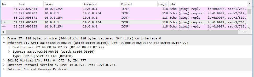
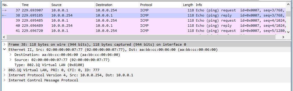
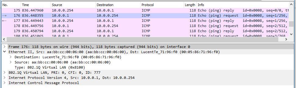
I will give a couple of screenshots from Wireshark. Here is the packet from CE1-1 to PE1: As the destination is not the local interface MAC interface irb.777 on PE1, but the MAC address irb.777 PE2. But what is remarkable: let's see from what address the answer from PE1 arrives at CE1-1: The answer is still PE1 sent from the native MAC address irb.777. That is, as you understand, irb.777 only accepts packets addressed to the MAC addresses of other irb.777 interfaces (PE2 and PE3), but does not use someone else's MAC addresses as a source address when sending a packet. This is very important, since, for example, when resolving the address of the default gateway, the IRB interface will respond and indicate only its native MAC address.
For the purity of the experiment, let us indicate to CE1-1 that the irb.777 MAC address is now equal to the irb.777 interface MAC address on PE3:
RZN-CE1-SW1#sh start | i arp arp 10.0.0.254 0005.8671.96f0 ARPA RZN-CE1-SW1#show arp | i 10.0.0.254 Internet 10.0.0.254 - 0005.8671.96f0 ARPA Naturally, on irb.777 PE3, I also hung this filter. Run the ping and check:
RZN-CE1-SW1#ping 10.0.0.254 repeat 27 Type escape sequence to abort. Sending 27, 100-byte ICMP Echos to 10.0.0.254, timeout is 2 seconds: !!!!!!!!!!!!!!!!!!!!!!!!!!! Success rate is 100 percent (27/27), round-trip min/avg/max = 1/2/5 ms Let's look in WIreshark to make sure that the packet with CE was sent with the necessary MAC address: Look at the counter on PE1:
bormoglotx@RZN-PE-1> show firewall filter irb777-counter counter irb777 Filter: irb777-counter Counters: Name Bytes Packets irb777 6000 60 irb.777 on PE1 processed another 27 packets, while on PE3 the counter stands at zero:
bormoglotx@RZN-PE-3> show firewall filter irb777-couter counter irb777 Filter: irb777-couter Counters: Name Bytes Packets irb777 0 0 This we have reviewed the automatic synchronization mechanism. We now turn to manual synchronization.
In general, manual synchronization is simply disabling automatic synchronization, due to the fact that it is simply not needed. Why?We have now configured on all PEs the same IP addresses on IRB interfaces, but different MACs. The second way to configure IRB interfaces in EVPN (the same as recommended) is the same IP and MAC addresses on all IRB interfaces of the same bridge domain. In this scenario, the IRB-interfaces are already synchronized, since the same MAC everywhere. Therefore, you can give the command default-gateway do-not-advertise and thus prohibit the generation of MAC + IP routes for IRB interfaces.
The big advantage of synchronizing default gateways is that it allows us to move virtual machines between data centers without interrupting the service (if certain conditions are met, such as a delay of less than 100ms between points A (where the machine moves) and Z (where the machine moves) and so on ). After moving the virtual machine, it can continue to send packets to the external network to the default gateway address, which is located in its arp — that is, we will not even have to clear the arp cache. Naturally, a new BGP Update will be generated, stating that now this MAC is in a different place. In general, on the topic of VM Mobility in EVPN, you need to write a separate rather big article and, therefore, we will not cover it now.
I hope that all of the above has been deposited in memory, because without this, the mechanism of operation of L3 interfaces in EVPN will not be clear. We now turn directly to the transfer of packets between bridge-domains.
Packet routing between bridge domains
We take as a basis the fact that within one bridge-domain packets are switched, and between different bridge-domains (or when leaving the external network) are routed. To allow traffic to be routed, we need to add routing interfaces to our instances. At JunOS, the routing interface is IRB (Integrated Routing and Bridging). This interface is not tagged, and the vlan tag is removed from the traffic that hits it. Like the usual interface on JunOS, IRB has units. The number of a unit in the IRB interface (as, in fact, the number of units on the physical interfaces) does not mean that this interface belongs to any particular vlan. For example, the irb.777 interface does not necessarily have to refer to the 777 vlan. But it is still more convenient to read the configuration files when the vlan number and the IRB number of the unit in the same bridge-domain are the same.
For testing, we will use the same lab as before, but add routing interfaces and a CE of routers to it, as indicated in the diagram:
For simplicity, in the article I will not indicate hostnames as they are shown in the diagram, but I will use abbreviations:
RZN-CE1-SW1 ⇒ CE1-1
RZN-CE1-SW2 ⇒ CE1-2
RZN-CE2-SW1 ⇒ CE2-1
RZN- CE2-SW2 ⇒ CE2-2
RZN-CE2-SW1 ⇒ CE3
At first glance, the scheme has a strange appearance, to put it mildly - all PE routers have the same IRB interfaces. I think that you should have at least two questions - how it works and why it is needed. Let's try to answer these questions.
So let's go.To begin, let us recall how the main (or default, as you like) gateway works in the VPLS we have already studied. We have some kind of PE router on which we create an IRB interface. We add the same IRB interface to a VRF or release it in GRTif there is such a need. It is possible that we have more than one such router, and we use vrrp to reserve the main gateway, but someone will still be the master. That is, in VPLS, we have only one access to the external network located on some PE router that is included in the VPLS domain. All outward traffic from all other PE routers will go through this PE-ku, as it is the only access to the external network (this, if you do not use crutches in the form of intentionally broken vrrp). The disadvantages of this scheme are obvious - PE, on which the default gateway will be located, will have to digest all outgoing traffic from the VPLS domain, sent to the external network and all traffic from the outside world that is included in the VPLS domain. And so, if this PE fails, and we have not assembled VRRP,then we will generally be cut off from other networks or the outside world. Oddly enough, but this scheme has its advantages - it is simplicity. To any engineer, the solution described above will be understandable both in terms of configuration and in terms of troubleshooting, which I cannot say about the solution used in EVPN.
In addition to the shortcomings described above, there is one more important nuance - in the scheme described above, we can’t optimize L3 traffic going inside or leaving the VPLS domain.
EVPN offers us a completely different way of using L3 interfaces. If the CE router wants to have access to the external network, other authorities or the Internet, then the default gateway as an L3 interface must be configured on the PE that this CE is connected to the router. Naturally, each vlan must have its own gateway.
It is noteworthy that the RFC does not explicitly state that every PE router must have an IRB interface in order to be able to go to the external network. But in the Juniper documentation for configuring EVPN there are such lines:
Initially when EVPN and Layer 3 gateway functionality were conceived, some basic assumptions were made, and RFC requirements were to be followed.
These were:
1. All PE's for an EVPN instance must have an IRB configured.
2. All PE's should have the same IP address for the GW. From the RFC, if there is a discrepancy between the GW IP addresses, an error is logged. Though it must be noted that different addresses can still be configured as both MAC/IP for advertisement to remote provider edge (PE) devices and are installed on all participating PE devices.
As a result, if you use EVPN / MPLS, then it is necessary to configure the L3 interface on each PE router, otherwise this site simply will not leave Vlan. But for EVPN / VXLAN this requirement is not (by the way, this is a significant difference between EVPN / VXLAN and EVPN / MPLS)
Let us return to our scheme. We have two bridge-domains - this is the domain VLAN-777 and VLAN-1777. In vlan 1777 we have two CE routers - this is CE1-2 and CE2-2, in vlan 777 there are three routers: CE1-1, CE2-1 and CE3. Naturally, I want to have connectivity between all the CE routers indicated in the diagram.
But in order to link several bridge-domains to each other, the mere addition of an L3 interface to the routing-instance EVPN is not enough. It is also necessary to create on each PE router a routing-instance with a VRF type (which is used for L3VPN), in which our L3 interfaces must be placed. Thus we will connect two instances: VRF and EVPN (or virtual-switch):
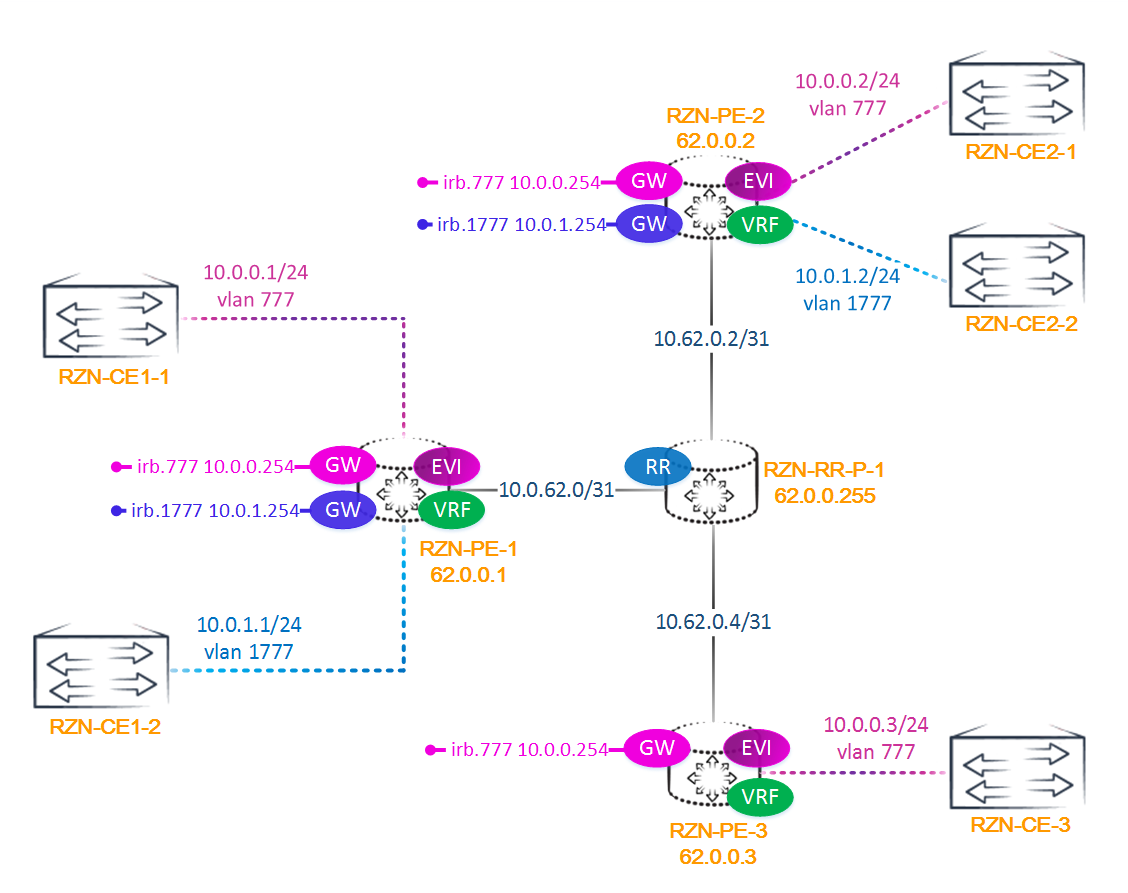
Note: you can release our EVPN in GRT , but it seems to me that this is not a good idea. In any case, this is supported, and everybody decides whether to implement this functionality or not.
As mentioned above, we need to configure the routing instance with a VRF type and associate it with EVPN. Below is the configuration with PE2 - virtual switch and its associated VRF:
bormoglotx@RZN-PE-2> show configuration routing-instances RZN-VPN-1 instance-type virtual-switch; interface ge-0/0/2.0; interface ge-0/0/3.0; route-distinguisher 62.0.0.2:1; vrf-import VPN-1-IMPORT; vrf-export VPN-1-EXPORT; protocols { evpn { extended-vlan-list [ 777 1777 ]; } } bridge-domains { VLAN-1777 { vlan-id 1777; routing-interface irb.1777; } VLAN-777 { vlan-id 777; routing-interface irb.777; } } bormoglotx@RZN-PE-2> show configuration routing-instances VRF-VPN-1 instance-type vrf; interface irb.777; interface irb.1777; route-distinguisher 62.0.0.2:10002; vrf-target { import target:6262:10001; export target:6262:10001; } vrf-table-label; The same VRFs rise on the other PE routers, except that the VRF on PE3 does not have the irb.1777 interface.
We already know that a type 2 route can optionally contain a host’s IP address. We have already seen the MAC + IP route itself: if you remember, when adding an IRB interface to EVPN, we generated two routes: just the MAC address of the IRB interface so that you can reach it inside the bridge domain without resorting to routing and MAC + IP, to which the default gateway was attached. The second route was necessary for routing and is an arp entry. But the MAC + IP route is generated not only for the default gateway. Such a route to any host will appear in the event that this host tries to go to the external network or another vlan.
What does the host need to get out of the vlan? True - you need to send the packet to the default gateway. In our case, the gateway for the bridge-domain is played by the PE PE IRB interface. And in order to send a packet to the IRB interface, the host needs to know the MAC address of this IRB interface. Therefore, to start, the host sends an arp request for resolving the MAC addresses of the IRB interface. At that moment, when the IRB interface receives an arp request from the host (in our case, the router's CE), which is directly connected to this PE router *, it generates two type 2 routes: only the MAC address and MAC + IP - and sends them via BGP in the form of EVPN routes. In addition, since the same route in the form of a normal IPv4 prefix with a mask / 32 will also appear in the associated with EVPN VRF, as a local route,then via BGP, the vpnv4 route to this host is also sent (why you need the second one - you will understand later). Actually, the above is the main principle of EVPN operation for routing between vlans, which allows to optimize the passage of traffic between different bridge-domains or between EVPN and external networks.
The table itself arp records can be viewed on each PE router. For example on PE2:
bormoglotx@RZN-PE-2> show bridge evpn arp-table INET MAC Logical Routing Bridging address address interface instance domain 10.0.1.2 aa:bb:cc:00:0a:00 irb.1777 RZN-VPN-1 VLAN-1777 10.0.1.22 aa:bb:cc:00:0a:00 irb.1777 RZN-VPN-1 VLAN-1777 10.0.1.222 aa:bb:cc:00:0a:00 irb.1777 RZN-VPN-1 VLAN-1777 10.0.0.2 aa:bb:cc:00:07:00 irb.777 RZN-VPN-1 VLAN-777 * 10.0.1.22 and 10.0.1.222 are the secondary addresses of CE2-2, hung during testing for dumping.
The output indicates which interface the arp request was made from, in which bridge-domain and the routing instance. This information will be useful, since the same MAC address may be in different Vlans or, as in the above output, there may be several addresses on the same physical interface, and, of course, they will have one MAC address. To all these hosts you will definitely find a route in the VRF:
bormoglotx@RZN-PE-2> show route table VRF-VPN-1.inet.0 active-path | match "(10.0.0.2\/)|(10.0.1.2{1,3}\/)" 10.0.0.2/32 *[EVPN/7] 00:09:38 10.0.1.2/32 *[EVPN/7] 09:11:03 10.0.1.22/32 *[EVPN/7] 02:02:40 10.0.1.222/32 *[EVPN/7] 01:54:26 Now let's move from theory to practice: let's look at how traffic will go from CE3 to CE1-2. The first is in vlan 777 and has an address of 10.0.0.3, the second in vlan of 1777 and has an address of 10.0.1.1. I remind you that on PE3 there is no local interface irb.1777.
So, CE3 wants to send a packet to CE1-2, which is on a different network. CE3 does not know the MAC address of the main gateway, so it makes an arp request for resolv address 10.0.0.254, which for this CE router is the main gateway to other networks. Naturally, on CE3 (and on all other CE routers, the default route is registered towards the IRB interface). Since PE3 receives an arp request from CE3 addressed to its local IRB interface, PE3 generates a MAC + IP route and sends it to the remaining PEs. In addition, since the route 10.0.0.3/32 appeared in the VRF as a local route, PE3 also announces the BGP vpnv4 route:
bormoglotx@RZN-PE-3> show route advertising-protocol bgp 62.0.0.255 | match 10.0.0.3 * 10.0.0.3/32 Self 100 I 2:62.0.0.3:1::777::aa:bb:cc:00:05:00::10.0.0.3/304 : , 2, MAC-, . , . PE MAC+IP . , — , , .
Moving on. CE3 now knows the MAC address of the default gateway, which means it knows where to send the packet addressed to CE1-1 (meaning the MAC address of the L2 header). CE3 forms a packet and in the L3 header the destination address indicates the address of CE1-1 (10.0.1.1), the outgoing address indicates its own address CE3 (10.0.0.3). In the L2 header, the destination address indicates the MAC address of irb.777, and the outgoing address indicates its own MAC address (the interface address in the direction of the PE of the router).
Package arrives at PE3. Since the destination MAC address is the irb.777 local interface, PE3 removes the L2 header and does an IP lookup in the VRF routing table that is associated with our EVPN-instance. There are currently four active routes in this table:
bormoglotx@RZN-PE-3> show route table VRF-VPN-1.inet.0 active-path VRF-VPN-1.inet.0: 4 destinations, 9 routes (4 active, 0 holddown, 0 hidden) + = Active Route, - = Last Active, * = Both 10.0.0.0/24 *[Direct/0] 00:20:05 > via irb.777 10.0.0.3/32 *[EVPN/7] 00:00:06 > via irb.777 10.0.0.254/32 *[Local/0] 04:04:34 Local via irb.777 10.0.1.0/24 *[BGP/170] 02:19:20, localpref 100, from 62.0.0.255 AS path: I, validation-state: unverified > to 10.62.0.5 via ge-0/0/0.0, Push 16, Push 299776(top) 10.0.0.0/24 and 10.0.0.3/32 are local for PE3 (the second one was just generated with an arp request for irb.777), but the route to the network 10.0.1.0/24 is received via BGP from PE1 and PE2.
Since PE1 and PE2 are created with the same VRF as PE3 (with the same RT), PE3 accepts all announcements from PE1 and PE2. On them (PE1 and PE2), in turn, the irb.1777 interface is added to this VRF, which means they will announce the route to the 10.0.1.0/24 network via BGP as a normal vpnv4 route, which will be imported into the VRF routing table on PE3. In the output above, only active routes are shown, so we see only one announcement, in total, of course, two - one received from PE1, the second - from PE2. The best choice is the route from PE1, since it has a smaller router-id, and all other parameters of the routes received from both PE-NIS are completely identical. Which route will be chosen the best - from PE1 or PE2 - is absolutely unimportant (for example, if we have 10 sites, we will get 9 routes to one network, but only one will be chosen),since all the same when receivingBUM traffic from the bridge-domain of VLAN-777, PE1 will flood it to all interfaces of the bridge-domain of VLAN-1777. Why - find out further.
During the IP lookup, PE3 learns that the prefix 10.0.1.0/24 is on PE1, so PE3 sends the packet via L3VPN to PE1:
bormoglotx@RZN-PE-3> show route table VRF-VPN-1.inet.0 10.0.1.0/24 active-path VRF-VPN-1.inet.0: 4 destinations, 9 routes (4 active, 0 holddown, 0 hidden) + = Active Route, - = Last Active, * = Both 10.0.1.0/24 *[BGP/170] 02:23:12, localpref 100, from 62.0.0.255 AS path: I, validation-state: unverified > to 10.62.0.5 via ge-0/0/0.0, Push 16, Push 299776(top) There is a possibility when traffic balancing on equivalent paths (ECMP) will be enabled on PE3 and two routes will be installed in the FIB, which means traffic can also go to PE2, but this, as I wrote above, is not important - the main thing is that the packet gets to PE a router on which there is a local bridge-domain VLAN-1777 (it cannot be any other way, unless, of course, you have any hard liking between VRFs configured). If there is no such bridge-domain on PE-ke, then there will be no announcement from it to the network 10.0.1.0/24.
PE1 accepts a packet from PE3 in VRF, does an IP lookup and understands that the packet is intended for the bridge-domain of VLAN-1777:
bormoglotx@RZN-PE-1> show route table mpls.0 label 16 mpls.0: 22 destinations, 23 routes (22 active, 0 holddown, 0 hidden) + = Active Route, - = Last Active, * = Both 16 *[VPN/0] 02:25:02 to table VRF-VPN-1.inet.0, Pop Since PE1 does not know the MAC address of the host 10.0.1.1, it floods the arp request to all interfaces of the bridge-domain VLAN-1777 to the resolver of this address. More specifically, one copy of the packet is sent to CE1-2, and the second, with an inclusive multicast tag to PE2. But what about the split horizon function? After all, the packet received from the PE router should not be sent to other PE routers. And then in fact we are breaking it without a twinge of conscience. The fact is that this packet came, according to L3VPN (that is, in fact, from some external network in relation to EVPN on PE1), therefore the split-horizon rule does not work here. But we know that the packet arrived from EVPN - will there be a broadcast storm? Although the packet arrived from evpn, but from another broadcast domain (CE3 is in vlan 777, and CE1-2 in vlan 1777). Since these are different bridge domains,then there can be no broadcast storm between them - packets are routed between bridge-domains.
Since CE1-2 is the destination host and is connected to PE1, it responds to the given arp request. As we remember, after receiving the arp addressed to the IRB interface from any host, the PE router should generate a type 2 MAC + IP route. In this regard, PE1 generates the MAC + IP and vpnv4 route:
bormoglotx@RZN-PE-3> show route table RZN-VPN-1.evpn.0 match-prefix *10.0.1.1* RZN-VPN-1.evpn.0: 19 destinations, 19 routes (19 active, 0 holddown, 0 hidden) + = Active Route, - = Last Active, * = Both 2:62.0.0.1:1::1777::aa:bb:cc:00:09:00::10.0.1.1/304 *[BGP/170] 00:02:46, localpref 100, from 62.0.0.255 AS path: I, validation-state: unverified > to 10.62.0.5 via ge-0/0/0.0, Push 299792 bormoglotx@RZN-PE-3> show route table VRF-VPN-1.inet.0 10.0.1.1/32 VRF-VPN-1.inet.0: 5 destinations, 10 routes (5 active, 0 holddown, 0 hidden) + = Active Route, - = Last Active, * = Both 10.0.1.1/32 *[BGP/170] 00:02:48, localpref 100, from 62.0.0.255 AS path: I, validation-state: unverified > to 10.62.0.5 via ge-0/0/0.0, Push 16, Push 299792(top) PE1 now has a MAC + IP route to host 10.0.0.3 in the EVPN routing table and 10.0.0.3/32 in the VRF routing table. Similarly, from the side of PE3: the route to the host 10.0.1.1/32 is in the routing table epn and VRF. It turns out that now the exchange of packets between CE3 and CE1-2 does not prevent anything. But there is one nuance. Let's look at the routing table in VRF on PE1:
bormoglotx@RZN-PE-1> show route table VRF-VPN-1.inet.0 10.0.0.3/32 VRF-VPN-1.inet.0: 7 destinations, 15 routes (7 active, 0 holddown, 0 hidden) + = Active Route, - = Last Active, * = Both 10.0.0.3/32 *[EVPN/7] 00:24:37, metric2 1 > to 10.62.0.1 via ge-0/0/0.0, Push 300352, Push 299792(top) [BGP/170] 00:24:37, localpref 100, from 62.0.0.255 AS path: I, validation-state: unverified > to 10.62.0.1 via ge-0/0/0.0, Push 16, Push 299792(top) On PE1 there are two routes to host 10.0.0.3/32, while on PE3 there is only one route to 10.0.1.1/32:
bormoglotx@RZN-PE-3> show route table VRF-VPN-1.inet.0 10.0.1.1/32 VRF-VPN-1.inet.0: 6 destinations, 11 routes (6 active, 0 holddown, 0 hidden) + = Active Route, - = Last Active, * = Both 10.0.1.1/32 *[BGP/170] 02:25:44, localpref 100, from 62.0.0.255 AS path: I, validation-state: unverified > to 10.62.0.5 via ge-0/0/0.0, Push 16, Push 299776(top) In VRF, there appeared some strange route with so far unknown to us the EVPN protocol, and yes even with preferential 7, which makes it better than BGP (and also preferable to ISIS, OSPF, etc.). It's strange, isn't it? What is this route? Why do we need it, because without it everything will work. The fact is that this route is necessary for direct traffic exchange between EVPN, bypassing L3VPN. Let's look at it carefully:
bormoglotx@RZN-PE-1> show route table VRF-VPN-1.inet.0 10.0.0.3/32 protocol evpn detail VRF-VPN-1.inet.0: 7 destinations, 15 routes (7 active, 0 holddown, 0 hidden) 10.0.0.3/32 (2 entries, 1 announced) *EVPN Preference: 7 Next hop type: Indirect Address: 0x97f5f90 Next-hop reference count: 2 Next hop type: Router, Next hop index: 615 Next hop: 10.62.0.1 via ge-0/0/0.0, selected Label operation: Push 300352, Push 299792(top) Label TTL action: no-prop-ttl, no-prop-ttl(top) Load balance label: Label 300352: None; Label 299792: None; Session Id: 0x1 Protocol next hop: 62.0.0.3 Label operation: Push 300352 Label TTL action: no-prop-ttl Load balance label: Label 300352: None; Composite next hop: 0x95117b8 670 INH Session ID: 0x2 Ethernet header rewrite: SMAC: 02:00:00:00:07:77, DMAC: aa:bb:cc:00:05:00 TPID: 0x8100, TCI: 0x0309, VLAN ID: 777, Ethertype: 0x0800 Indirect next hop: 0x9860990 1048583 INH Session ID: 0x2 State: <Active NoReadvrt Int Ext> Age: 1:09 Metric2: 1 Validation State: unverified Task: RZN-VPN-1-evpn Announcement bits (1): 0-KRT AS path: I We are interested in the following lines of this output:
Ethernet header rewrite: SMAC: 02:00:00:00:07:77, DMAC: aa:bb:cc:00:05:00 TPID: 0x8100, TCI: 0x0309, VLAN ID: 777, Ethertype: 0x0800 This is nothing but an indication of which L2 header to add in order to send a packet to CE3! Let's see what the MAC address is listed as the source: SMAC: 00: 05: 86: 71: 1a: f0. It is logical that if this is the source of the packet, then it should be on PE1. Let's estimate, from what MAC-address can packets leave in vlan 777? It is logical to assume that this will be the irb.777 interface, which means that its L2 header should be its MAC. Let's see what is actually the MAC address of irb.777:
bormoglotx@RZN-PE-1> show interfaces irb.777 | match mac MAC: 02:00:00:00:07:77 That's right, the header contains the MAC address of the local interface irb.777 on PE1, which means our reasoning was correct. Let's now identify who the destination MAC address belongs to: DMAC: aa: bb: cc: 00: 05: 00? I think it is not worth guessing - it should be MAC CE3. Let's check:
bormoglotx@RZN-PE-1> show route table RZN-VPN-1.evpn.0 match-prefix *10.0.0.3* RZN-VPN-1.evpn.0: 21 destinations, 21 routes (21 active, 0 holddown, 0 hidden) + = Active Route, - = Last Active, * = Both 2:62.0.0.3:1::777::aa:bb:cc:00:05:00::10.0.0.3/304 *[BGP/170] 00:05:18, localpref 100, from 62.0.0.255 AS path: I, validation-state: unverified > to 10.62.0.1 via ge-0/0/0.0, Push 299792 This MAC belongs to the host 10.0.0.3, where it indicates the route. To be sure, let's go to CE3 and see how the MAC on its interface is towards PE:
RZN-CE3-SW1#sh ip int br | i 10.0.0.3 Ethernet0/0.777 10.0.0.3 YES NVRAM up up RZN-CE3-SW1#sh interfaces eth0/0.777 | i Hard Hardware is AmdP2, address is aabb.cc00.0500 (bia aabb.cc00.0500) Affiliation of addresses we have established. Now let's look at the second line of the output part of interest:
TPID: 0x8100, TCI: 0x0309, VLAN ID: 777, Ethertype: 0x0800 And these are the values that you need to fill in the remaining ethernet fields of the frame when sending to CE3.
That is, this route clearly indicates to us that if you need to send an ethernet frame from irb.777 to host CE3, then you need to add the specified values to the L2 header, hang two tags: Push 300352, Push 299792 (top) and send the packet to the ge- interface 0/0 / 0.0. It's simple.
Note: this action with the package implies the use of a composite next hop. That is why the inclusion of the chained-composite-next-hop functionality is mandatory on Juniper, when configuring EVPN.
bormoglotx@RZN-PE-1> show configuration routing-options forwarding-table chained-composite-next-hop { ingress { evpn; } } Where does this route come from? Maybe PE3 sent it to us? Let's check that PE3 announces on the reflector:
bormoglotx@RZN-PE-3> show route advertising-protocol bgp 62.0.0.255 | match 10.0.0.3 * 10.0.0.3/32 Self 100 I 2:62.0.0.3:1::777::aa:bb:cc:00:05:00::10.0.0.3/304 Nothing criminal, only two routes have the address 10.0.0.3. The first is the vpnv4 route, the second is EVPN type 2.
So this route is local to the PE router. That's right.This route is generated by the local PE router based on the EVPN MAC + IP route. But then why is it not on PE3? Using the method of banal erudition, we can come to the conclusion that PE3 does not have a bridge-domain vlan 1777 with interface irb.1777 (after all, the package should go to CE1-2) and interface irb.1777 is not in the associated VRF. And since there is no local interface, what MAC address should be specified as source? You can not put the address of another interface. That is why this route is absent on PE3. Let's check this theory - we deactivate irb.777 interface on PE1 in the VRF interface, from which the packet will have to fly to PE3.
So, the route to PE1 is now:
[edit] bormoglotx@RZN-PE-1# run show route table VRF-VPN-1.inet.0 10.0.0.3/32 VRF-VPN-1.inet.0: 8 destinations, 18 routes (8 active, 0 holddown, 0 hidden) + = Active Route, - = Last Active, * = Both 10.0.0.3/32 *[EVPN/7] 00:01:22, metric2 1 > to 10.62.0.1 via ge-0/0/0.0, Push 300352, Push 299792(top) [BGP/170] 00:04:41, localpref 100, from 62.0.0.255 AS path: I, validation-state: unverified > to 10.62.0.1 via ge-0/0/0.0, Push 16, Push 299792(top) Deactivate the IRB interface in VRF on PE1:
[edit] bormoglotx@RZN-PE-1# show | compare [edit routing-instances VRF-VPN-1] ! inactive: interface irb.777 { ... } And check that we have a route to 10.0.0.3/32:
[edit] bormoglotx@RZN-PE-1# run show route table VRF-VPN-1.inet.0 10.0.0.3/32 VRF-VPN-1.inet.0: 7 destinations, 13 routes (7 active, 0 holddown, 0 hidden) + = Active Route, - = Last Active, * = Both 10.0.0.3/32 *[BGP/170] 00:05:47, localpref 100, from 62.0.0.255 AS path: I, validation-state: unverified > to 10.62.0.1 via ge-0/0/0.0, Push 16, Push 299792(top) Well, let's check, and will there be a ping?
RZN-CE1-SW2#ping 10.0.0.3 Type escape sequence to abort. Sending 5, 100-byte ICMP Echos to 10.0.0.3, timeout is 2 seconds: !!!!! Success rate is 100 percent (5/5), round-trip min/avg/max = 11/14/21 ms Naturally, the ping passed, but now the traffic goes through L3VPN in both directions. But I want to say that even in such a scenario, the traffic route is optimized. The same will happen if the bridge-domain of VLAN-777 is removed from the configuration (in this case, irb.777 will still be in the VRF, but in the down state, since for the IRB interface to be in the up, at least one physical interface is needed able up in the bridge-domain in which the IRB-interface is located).
But we stopped at the fact that the package from CE3 reached CE1-2. Now CE1-2 wants to respond to this package. Here we will do without conclusions from the CLI.
So, CE1-2 sends a packet to the address of the main gateway, the address of which it already knows. PE1 accepts a packet in the bridge domain VLAN-1777. Since in the packet in the L2 header, the destination address is irb.1777, PE1 removes the L2 header and does an IP lookup in the VRF routing table. In the routing table there is a route to the host 10.0.0.3/32, and, as shown above, there are two routes and the best EVPN. PE1 simply changes the L2 header, sticks tags and sends a packet to PE3.
PE3 receives the packet, sees a label that indicates that the L2 lookup needs to be done in the bridge-bridge MAC table of VLAN-777, and, according to the information in it, forward the packet to CE3.
Actually, we have reviewed the entire process that occurs with the package, as it moves from CE3 to CE1-2 and back. But we considered the process at a time when there was no traffic between these nodes and the PE routers did not know the MAC addresses of CE1-2 and CE3. After the addresses became known and the routes scattered across all the PEs, the traffic will go a little differently. Let's take a quick look at how traffic will eventually go:
From CE3 to CE1-2:
- The package from CE3 falls into the bridge-domain Vlan 777 on PE3.
- PE3 does an IP lookup in the associated VRF and sees a specific route to host 10.0.1.1/32. Since there is no local bridge vlan 1777 on PE3, there is no EVPN route either. So traffic goes through L3VPN to PE1.
- PE1 accepts the packet in the VRF, removes the label from it and sees that it is intended for the bridge-bridge vlan 1777.
- PE1 sends a packet to CE2-1 according to the MAC table of the bridge domain vlan 1777.

Now pack in the opposite direction From CE1-2 to CE3:
- CE1-2 sends a reply packet to PE1.
- PE1 does an IP lookup in VRF and sees the route to the host 10.0.0.3/32, and the best route is the EVPN route.
- PE1 sticks a new L2 header and adds a stack of two labels, according to the information contained in the EVPN route in the associated VRF.
- PE3 accepts a packet from PE1, removes the label and sees that it is necessary to do L2 lookup in the MAC table of the bridge-domain VLAN-777.
- PE3 then forwards the packet to CE3.

As you can see, in the opposite direction the package flies a little differently - this is called asymmetric forwarding. A reasonable question arises - why asymmetric? The fact is that ingress PE does an IP lookup in the VRF and sends a packet based on the route that EVFN has in the VRF, but the egress PE already accepts the packet not in the VRF, but in the EVPN instance. If we compare the last two schemes, the symmetry and asymmetry of traffic will be clearly visible. I think everyone understood how it works.
The scheme, which we have disassembled, is called a scheme with a symmetric use of IRB interfaces (different vendors can call this scheme differently, this term is taken from the manuals for configuring EVPN on Brocade). An asymmetric scheme will be a scheme when all PE routers have the same IRB interfaces, even if the specified vlan does not exist on this PE router. The advantage of the asymmetric scheme is that in all VRFs there will be EVPN protocol routes ([EVPN / 7]) and your traffic will not go one way through L3VPN, but back directly to EVPN. In our case, if we add irb.1777 to PE3 to the scheme, we will get an asymmetric scheme.
But there is one more thing that needs to be illuminated.
As you know, an ARP request is sent to a broadcast address, and the answer to it is forwarded back to the sender's MAC address specified in the header.
In the above case, CE1-2 was directly connected to PE1 and everything worked normally: PE1 sent an arp request, and CE1-2 answered it - in fact, no problems. But, if CE3 sent a packet to CE2-2, the events would have evolved somewhat differently. At first, everything is the same as described earlier:
- PE3 looks at the VRF routing table and sees the route to the 10.0.1.0/24 network received from PE1.
- PE3 has no other options than to send a packet via L3VPN to PE1.
- PE1 accepts the packet, makes the L3 lookup and forwards it to the bridge-domain of VLAN-1777. Since irb.1777 does not yet know the MAC address of CE2-2, it initiates an arp request for resolving the address of CE2-2 (10.0.1.2), sending the packet to CE1-2 and PE2.
- CE1-2 drops the packet, since the address 10.0.1.2 does not belong to it. PE2 forwards the received request to CE2-2.
- CE2-2 accepts the arp request and responds with a unicast to the MAC address belonging to irb.1777 to PE1.
But will irb.1777 on PE1 get a response from CE2-2? We recall the synchronization of MAC addresses between default gateways. Remember?So you understand that irb.1777 on PE2 will receive a packet directed to the MAC address of irb.1777 PE1. As a result, PE1 will not receive a response to its request, no matter how much it sends them, which means it will not split the destination IP address and will not be able to send a packet to CE2-2. It would have been like that if it hadn't been EVPN.
Since irb.1777 on PE2 received arp from CE2-2, it generates a type 2 route (MAC and MAC + IP), as well as a vpnv4 prefix. As you understand, PE1 no longer needs an answer to its arp request, since now it received the MAC address of CE2-2 via BGP and can send it a packet that was in the buffer. It turns out that traffic to CE2-2, which lives on PE2 comes with a PE3 loop through PE1? Not certainly in that way.Loop came only package (or packages), which PE3 has already managed to send and which were in the queue to send to PE1. But since, as on PE3, a more specific route to CE2-2 appeared in VRF, the traffic will no longer go through PE1 via route 10.0.1.0/24, but directly to PE2 (via route 10.0.1.2/32, which will appear in VRF routing table).
In the case we considered, all the IRB interfaces had different MAC addresses, which implied the need to synchronize the default gateways. The recommended use of IRB interfaces is to use the same MAC and IP addresses on all PE routers of the same bridge domain. As you understand, when MAC addresses are the same everywhere and everything will work as I described above, only synchronization of default gateways is essentially not necessary.
Ultimately, in any case, no matter how you use IRB interfaces:
with the same IP, but different MAC addresses;
with the same IP and MAC addresses,
anyway, all PE routers in the EVPN domain will receive the MAC + IP route and the BGP vpnv4 prefix, which means that when sending a packet from another CE router, you will not need to send the arp request again to the resolver. This allows you to significantly reduce arp flooding on the provider's network.
Exit to other VRF and external networks
Above, we have analyzed how the traffic will go between the vlans. But what about access from other VRF unrelated evpn?
Let's try to reach for example the host 10.0.1.1/32 of a VRF that is not associated with any EVPN. I don’t want to make a new VRF, so I’ll do it easier: deactivate instance evpn on PE3, deactivate irb.777 in VRF and add a new interface irb.0 (20.0.0.1/24):

[edit] bormoglotx@RZN-PE-3# show routing-instances RZN-VPN-1 ## ## inactive: routing-instances RZN-VPN-1 ## instance-type evpn; vlan-id 777; interface ge-0/0/2.777; routing-interface irb.777; route-distinguisher 62.0.0.3:1; vrf-import VPN-1-IMPORT; vrf-export VPN-1-EXPORT; protocols { evpn { interface ge-0/0/2.777; } } [edit] bormoglotx@RZN-PE-3# show routing-instances VRF-VPN-1 instance-type vrf; interface irb.0; inactive: interface irb.777; route-distinguisher 62.0.0.3:10003; vrf-target { import target:6262:10001; export target:6262:10001; } vrf-table-label; [edit] bormoglotx@RZN-PE-3# show interfaces irb.0 family inet { address 20.0.0.1/24; We look at what we have in the routing table:
bormoglotx@RZN-PE-3> show route table VRF-VPN-1.inet.0 active-path VRF-VPN-1.inet.0: 7 destinations, 9 routes (7 active, 0 holddown, 0 hidden) + = Active Route, - = Last Active, * = Both 10.0.0.0/24 *[BGP/170] 00:00:03, localpref 100, from 62.0.0.255 AS path: I, validation-state: unverified > to 10.62.0.5 via ge-0/0/0.0, Push 16, Push 299776(top) 10.0.1.0/24 *[BGP/170] 00:00:03, localpref 100, from 62.0.0.255 AS path: I, validation-state: unverified > to 10.62.0.5 via ge-0/0/0.0, Push 16, Push 299776(top) 10.0.1.1/32 *[BGP/170] 00:00:03, localpref 100, from 62.0.0.255 AS path: I, validation-state: unverified > to 10.62.0.5 via ge-0/0/0.0, Push 16, Push 299776(top) 10.0.1.2/32 *[BGP/170] 00:00:03, localpref 100, from 62.0.0.255 AS path: I, validation-state: unverified > to 10.62.0.5 via ge-0/0/0.0, Push 16, Push 299792(top) 10.0.1.22/32 *[BGP/170] 00:00:03, localpref 100, from 62.0.0.255 AS path: I, validation-state: unverified > to 10.62.0.5 via ge-0/0/0.0, Push 16, Push 299792(top) 20.0.0.0/24 *[Direct/0] 00:00:03 > via irb.0 20.0.0.1/32 *[Local/0] 00:00:03 Local via irb.0 I specifically deactivated this VRF to show that the routes / 32 will immediately arrive in the form of vpnv4 prefixes and stand in the routing table (as you can see the lifetime of the route in the table for all prefixes is the same and equals three seconds).
Now we’ll run the ping from our IRB interface (20.0.0.1) on CE1-2 (10.0.1.1), which lives behind PE1:
bormoglotx@RZN-PE-3> ping rapid routing-instance VRF-VPN-1 source 20.0.0.1 10.0.1.1 PING 10.0.1.1 (10.0.1.1): 56 data bytes !!!!! --- 10.0.1.1 ping statistics --- 5 packets transmitted, 5 packets received, 0% packet loss round-trip min/avg/max/stddev = 5.828/7.872/10.368/1.655 ms And now before the host CE2-2 10.0.1.2, who lives on PE2:
bormoglotx@RZN-PE-3> ping rapid routing-instance VRF-VPN-1 source 20.0.0.1 10.0.1.2 PING 10.0.1.2 (10.0.1.2): 56 data bytes !!!!! --- 10.0.1.2 ping statistics --- 5 packets transmitted, 5 packets received, 0% packet loss round-trip min/avg/max/stddev = 5.443/6.713/7.342/0.656 ms Now back to the routes and see if the packages go in different ways:
bormoglotx@RZN-PE-3> show route table VRF-VPN-1.inet.0 10.0.1.1/32 VRF-VPN-1.inet.0: 7 destinations, 9 routes (7 active, 0 holddown, 0 hidden) + = Active Route, - = Last Active, * = Both 10.0.1.1/32 *[BGP/170] 00:03:50, localpref 100, from 62.0.0.255 AS path: I, validation-state: unverified > to 10.62.0.5 via ge-0/0/0.0, Push 16, Push 299776(top) bormoglotx@RZN-PE-3> show route table VRF-VPN-1.inet.0 10.0.1.2/32 VRF-VPN-1.inet.0: 7 destinations, 9 routes (7 active, 0 holddown, 0 hidden) + = Active Route, - = Last Active, * = Both 10.0.1.2/32 *[BGP/170] 00:03:52, localpref 100, from 62.0.0.255 AS path: I, validation-state: unverified > to 10.62.0.5 via ge-0/0/0.0, Push 16, Push 299792(top) So, up to 10.0.1.1 the transport label 299776, and up to 10.0.1.2 - 299792. We look at what the LSP is:
Label 299776 is a transport label up to 62.0.0.1 (PE1):
bormoglotx@RZN-PE-3> show route 62.0.0.1/32 table inet.3 inet.3: 3 destinations, 3 routes (3 active, 0 holddown, 0 hidden) + = Active Route, - = Last Active, * = Both 62.0.0.1/32 *[LDP/9] 03:36:41, metric 1 > to 10.62.0.5 via ge-0/0/0.0, Push 299776 Tag 299776 - transport tag up to 62.0.0.2 (PE2):
bormoglotx@RZN-PE-3> show route 62.0.0.2/32 table inet.3 inet.3: 3 destinations, 3 routes (3 active, 0 holddown, 0 hidden) + = Active Route, - = Last Active, * = Both 62.0.0.2/32 *[LDP/9] 03:36:45, metric 1 > to 10.62.0.5 via ge-0/0/0.0, Push 299792 As you can see, even from VRF, which knows absolutely nothing about EVPN, traffic goes the best way. The reverse traffic from EVP to VRF to the network 20.0.0.0/24 follows the route obtained via BGP:
bormoglotx@RZN-PE-2> show route table VRF-VPN-1.inet.0 20.0.0.0/24 active-path VRF-VPN-1.inet.0: 10 destinations, 16 routes (10 active, 0 holddown, 0 hidden) + = Active Route, - = Last Active, * = Both 20.0.0.0/24 *[BGP/170] 00:06:44, localpref 100, from 62.0.0.255 AS path: I, validation-state: unverified > to 10.62.0.3 via ge-0/0/0.0, Push 16, Push 299808(top) Package path from VRF (irb.0 20.0.0.1) to EVPN (CE1-2 10.0.1.1):

Return traffic route:

But the presented case is simple - routes to hosts 10.0.1.1 and 10.0.1.2 were already in the routing table. What if there is no route to the host? Here everything works the same way as in the first case (when there is no bridge-domain on the PE router in which the destination host lives). Let's reach for example 10.0.0.2, which we don’t currently have a specific route to:
bormoglotx@RZN-PE-3> show route table VRF-VPN-1.inet.0 10.0.0.2/32 bormoglotx@RZN-PE-3> There really is no route, but we have a route to 10.0.0.0/24:
bormoglotx@RZN-PE-3> show route table VRF-VPN-1.inet.0 10.0.0.0/24 | match \/24 10.0.0.0/24 *[BGP/170] 00:13:14, localpref 100, from 62.0.0.255 It is logical that the traffic will go along this route. Run ping and verify that everything works:
bormoglotx @ RZN-PE-3> ping rapid routing-instance VRF-VPN-1 source source 20.0.0.1 10.0.0.2
PING 10.0.0.2 (10.0.0.2): 56 data bytes !!!!! --- 10.0.0.2 ping statistics --- 5 packets transmitted, 5 packets received, 0% packet loss round-trip min/avg/max/stddev = 6.135/7.206/7.806/0.663 ms Ping successfully passed, and in VRF we had a route to host 10.0.0.2/32:
bormoglotx@RZN-PE-3> show route table VRF-VPN-1.inet.0 10.0.0.2/32 VRF-VPN-1.inet.0: 9 destinations, 11 routes (9 active, 0 holddown, 0 hidden) + = Active Route, - = Last Active, * = Both 10.0.0.2/32 *[BGP/170] 00:00:06, localpref 100, from 62.0.0.255 AS path: I, validation-state: unverified > to 10.62.0.5 via ge-0/0/0.0, Push 16, Push 299792(top) I hope you understand how it works.
Why is it still needed?
One of my friends dubbed this technology - drug addiction. It is possible that the algorithm for using the IRB interface is too complicated and difficult to understand, not only in terms of work, but also in terms of why it is needed at all. But remember, when you first heard about MPLS - did you really understand this technology? I think that is unlikely.
But why it was impossible to do the same as in VPLS - one way out of the entire domain? Let's think about what problem the use of the L3 interface described above solves. EVPN was essentially designed to connect data centers. From the data center comes a very decent amount of traffic, in contrast to the simple client VPLS. Therefore, consider the following case:
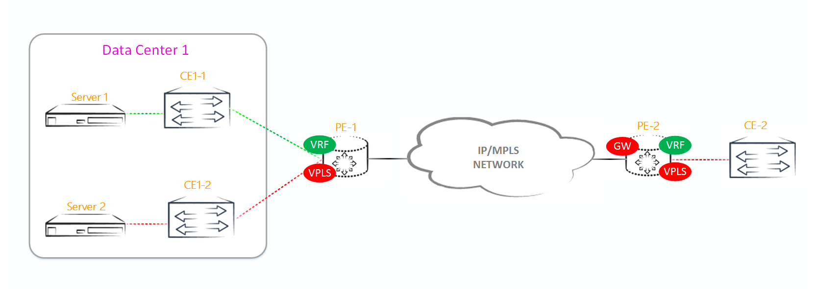
We have one exit point from VPLS, located on PE2, and suppose that CE1 is connected to L3VPN, and CE2 to VPLS domain. The important thing is that both of these grids will live in the same datacenter, but the traffic between them will go along such a loop:
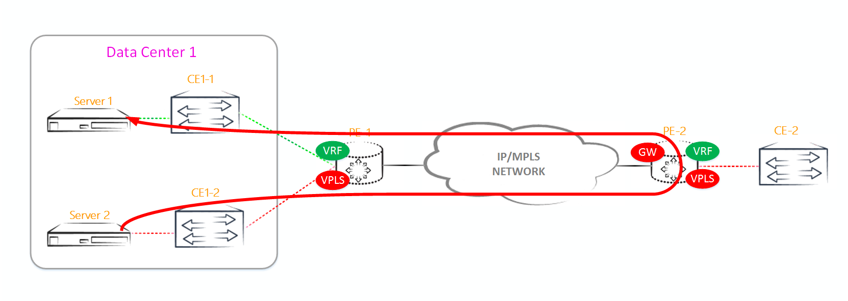
First, the traffic from Server 2 goes to the exit from the VPLS domain, which is on PE2, and from PE2, through L3VPN it returns back to PE1. It is possible that even these two servers will be included in the same switch and / or stand in the same cabinet in the data center. Yes, if this is some kind of low traffic volume, then let it go like this - most likely, the game is not worth the trouble. But, if this is a streaming video, downloading any content from an FTP server and so on? Then all this amount of traffic passes through the network core twice, simply clogging the bandwidth with essentially “spurious” traffic. This is exactly the task that the L3 EVPN functionality solves. By generating a / 32 route to the host and transferring it to the VRF, EVPN optimizes the flow of traffic between different networks. If you use EVPN in the above scheme, then PE1 would generate a / 32 route to server1,and the traffic would go locally through PE1, and not loop through the entire core:
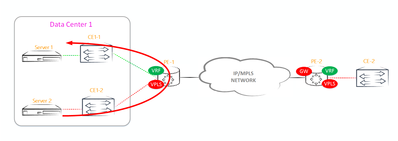
And this is just one example ...
Conclusion
As you can see, EVPN is not just a Level 2 technology. Routing and switching are deeply integrated into this technology. Moreover, it is not necessary to use the above-described scheme with integration into the VRF, if you simply pass through the client L2 service.
But for everything in this world you have to pay and EVPN is no exception. The fact that the technology is complicated and confused is not a problem, you just have to figure it out (because when the VPLS seemed like a dark forest - and now it seems that everything seems logical and understandable (in any case, to me)). One of the problems can be a large number / 32 and a large number of type 2 routes, which will sometimes be unrealistic to understand. Let's estimate that we have, for example, 4 networks, the size of / 24 - roughly speaking, these are networks with 250 hosts. If we want all the hosts to communicate with each other, then we get 1000 routes / 32 (250 routes / 32 and type 2 on each network / 24). And if such domains will be 10? Then already 10,000 masked routes / 32 will fly through our network, loading the control plane.Moreover, these figures in the realities of modern data centers with their virtualization systems will be 2-3 orders higher than those described in the article. We know that router reflector sends to its neybor all the routes allowed by group export policy. If, for example, we add a PE4 router to our topology, which will have a vpnv4 session with a reflector, then it will receive all our 10,000 routes from the reflector, which are not particularly needed for it. Naturally, PE4 will look at RT and discard the announcement, but this work will also load the RE processor. There is no recommendation in the RFC about this. Juniper also recommends using the route-target family of addresses in order to receive only the necessary announcements. But in my practice I have received so far only problems from this address family.that the router will send to its neybor all the routes allowed by group export policy. If, for example, we add a PE4 router to our topology, which will have a vpnv4 session with a reflector, then it will receive all our 10,000 routes from the reflector, which are not particularly needed for it. Naturally, PE4 will look at RT and discard the announcement, but this work will also load the RE processor. There is no recommendation in the RFC about this. Juniper also recommends using the route-target family of addresses in order to receive only the necessary announcements. But in my practice I have received so far only problems from this address family.that the router will send to its neybor all the routes allowed by group export policy. If, for example, we add a PE4 router to our topology, which will have a vpnv4 session with a reflector, then it will receive all our 10,000 routes from the reflector, which are not particularly needed for it. Naturally, PE4 will look at RT and discard the announcement, but this work will also load the RE processor. There is no recommendation in the RFC about this. Juniper also recommends using the route-target family of addresses in order to receive only the necessary announcements. But in my practice I have received so far only problems from this address family.then he will receive from our reflector all of our 10,000 routes, which he doesn’t really need. Naturally, PE4 will look at RT and discard the announcement, but this work will also load the RE processor. There is no recommendation in the RFC about this. Juniper also recommends using the route-target family of addresses in order to receive only the necessary announcements. But in my practice I have received so far only problems from this address family.then he will receive from our reflector all of our 10,000 routes, which he doesn’t really need. Naturally, PE4 will look at RT and discard the announcement, but this work will also load the RE processor. There is no recommendation in the RFC about this. Juniper also recommends using the route-target family of addresses in order to receive only the necessary announcements. But in my practice I have received so far only problems from this address family.
On top of that, let's answer a simple question: why aren't MAC addresses used for routing? Indeed, unlike IPv4 addresses, there are more MAC addresses, they are globally unique, there are both broadcast and multicast addresses, there are even private (or, more precisely, manually assigned by administrators regardless of the equipment manufacturer) MAC addresses. Use - I do not want! But for some reason IP is used with all its crutches like NAT and so on. One of the most important reasons is that MAC addresses, unlike IP addresses, are not aggregated in a subnet, since the first part of them is not responsible for geographical the location of the address or the organization to which this block of addresses was issued, but for the equipment belonging to one or another manufacturer. In the end, it turns out that theoretically, MAC addresses are amenable to aggregation, but practically on a live network it is impossible to do this,for example, the MAC address 04: 01: 00: 00: 01: 01 belongs to a piece of iron located somewhere on the coast of Florida, and the piece of hardware with a MAC address is 04: 01: 00: 00: 01: 02 for example, already in Ryazan.
Today, FV has more than 600,000 aggregated routes. Imagine the size of the routing table if only 32 addresses were used for routing. Why am I writing about this? The fact is that if you have 5-6 data centers connected in which there are about 100k MAC addresses, then imagine what load will lie on the control plane on the distribution of only EVPN routes (about the same number / 32 I am silent). This problem has solutions, for example, using PBB , but, as they say, this is a completely different story ...
If someone is more interested in digging deeper, then here are some links to information on this topic:
→ Immediately RFC 7432 itself with the entire history of changes;
→ Juniper EVPN;
→ Juniper EVPN IRB ;
→ Cisco EVPN PBB ;
→ Cisco EVPN VXLAN ;
→ Brocade EVPN .
Links to all previous issues of SDSM:
From the author
Writing an article, testing various functions, reading the RFC and other available literature from various vendors (not limited to Cisco and Juniper) took more than 2 months. As you can see, the tests were conducted exclusively at Juniper, and for other vendors the implementation of some functionality may differ slightly from that described above. I hope the article will be clear and useful to readers. If you found typos in the article or some shoals - write in a personal. Well, thank you for your attention ...
Source: https://habr.com/ru/post/316792/
All Articles