Own platform. Part 0.2 Theory. CHIP8 interpreter
Introduction
Hello world! Today we have a translation of the CHIP8 language specification. This article contains only a theoretical part.

What is CHIP8?
CHIP8 is an interpreted programming language that was developed by Joseph Weisbecker (note: translation by Joseph Weisbecker) in the seventies for use in RCA COSMAC VIP . Later it was used in COSMAC ELF , Telmac 1800 , ETI 660, DREAM 6800. Thirty-one (35?) Instructions made it possible to output a simple sound, monochrome graphics at a resolution of 64 by 32 pixels, and also allowed the use of 16 custom buttons. Today, CHIP-8 is often used to teach basic emulation skills (not interpretations). CHIP-8 interpreters, often mistakenly called “emulators,” exist on an ever-expanding array of platforms. This abundance of interpreters is associated with the similarity of the design of the CHIP-8 interpreter and the system emulator. Those who want to understand emulators often begin by writing the CHIP-8 interpreter.
Because of its simplicity, a large number of games and programs were written in CHIP-8. This proves that a programmer is often not limited to a programming language.
CHIP-8 instructions are stored directly in memory. Modern computers allow you to store binary data without the need to enter them manually into memory. The COSMAC VIP specification assumes that the code is loaded into memory with an offset of 512 bytes (0x200). Most of the games and programs in CHIP-8, while working with memory, assume just such a shift.
It should be noted that the programs in the memory of CHIP-8 are stored in Big-Endian, assuming the storage is MSB First (Most Significant Byte First - the most "significant" byte is stored first). Instructions are executed two bytes sequentially if there are no other instructions.
Since CHIP-8 instructions contain pointers to data or instructions in memory, changing the code would require changing the address in the instructions. Fortunately, a pseudo-assembler solves this problem. A large number of documentation for CHIP-8 does not contain a description of some instructions (8XY3, 8XY6, 8XY7 and 8XYE), but will be described here.
Architecture
GPR General Purpose Registers (RON - General Purpose Registers)
All arithmetic operations use registers. CHIP-8 describes 16 registers. All registers are unsigned, 8-bit, and can take general-purpose registers as arguments in instructions, but it is worth remembering that some instructions can modify the last register (V [0xF]) (Overflow register).
Pseudocode:
u8 V[16] <= 0; Do not make my mistakes: The last register is a full 8-bit register, despite being used as a special register in some instructions. Although the specification recommends not using the last register in operations.
I (Register)
Register I is a 16-bit register. Despite this, it uses only the first 12 bits.
Pseudocode:
u16 I <= 0; Omission in the specification: What happens if an overflow occurs?
PC (Register)
The PC register is similar to the I register, only indicates instructions.
Omission in the specification: What happens if an overflow occurs?
Stack
In CHIP-8, a stack with a depth of 12 cells is described. There is no direct access to the stack (PUSH / POP / etc), but there are call and return instructions that use the stack.
NOTE: It is indicated 16 cells. And here - 12.
Instructions
All instructions are in hexadecimal notation.
Designations, see the table:
- NNN: Address
- NN: 8-bit constant.
- N: 4-bit constant.
- X and Y: Registers
- PC: Program Counter (Team Counter?)
- I: 16 bit pointer (register?)
Registers and arithmetic
6XNN - Load constant in register.
The simplest instruction for registers is 6XNN (hexadecimal notation). Where X is a register and NN is a constant loaded into a register. For example, 6ABB - Load in register number 10 (V [0xA], registers 16 from zero to fifteen) the value BB (187).
Pseudocode:
V[X] <= 0xNN 7XNN - Add constant to register (ADDI)
Adds the constant NN to the register under the number X and stores it in the register under the number X. Does not change the register of overflow.
V[X] <= V[X] + NN 8XY0 - Save the register to another register (MOV)
Another instruction working with registers. Has a record 8XY0 . Where X is the register number where the register under number Y will be copied.
Pseudocode:
V[X] <= V[Y] 8XY4 - Add two registers (ADD)
Adds the register value under the Y number to the X register and stores the value in the X register. If an overflow occurs, the overflow register will be set to 1. If the overflow has not occurred, the overflow register will be reset to 0.
V[X] <= (V[X] + V[Y]) & 0xFF; V[F] <= (V[X] + V[Y] >= 256); Do not make my mistakes: The overflow register will be modified in any case.
Omission in the specification: What happens if the register X is an overflow register?
8XY5 - Subtract from register (SUB)
Subtracts from the register under the number X the value of the register Y and if there was a borrowing (approx. Translation Borrow) set the overflow register to 1. And set the overflow register to 0 if there was no borrowing.
8XY7 - Reverse Subtraction (SUB)
Set the register number X to the result of subtracting the value of register X from register Y. And if there was a borrowing, set the overflow register to 1. And set the overflow register to 0 if there was no borrowing.
8XY2, 8XY1 and 8XY3 - Boolean operations (AND, OR, XOR)
Set register X to operation result
8XY2 - Logic "AND",
8XY1 - logical "OR",
8XY3 - Exclusive OR
two operands: the register of X and the register of Y. Does not modify the register of overflow.
Do not make my mistakes: These operations DO NOT MODIFY the overflow register.
NOTE: There is no typo. 8XY2 - AND. 8XY1 OR. 8XY3 XOR.
8XY6 - Shift Right
Save to register X the result of shifting register Y to the right.
Set the overflow register to the low-order bit of the Y register.
Do not make my mistakes: The result of the shift of the register Y is stored in the register X, and not in the register Y. Although many interpreters ignore this rule.
8XYE - Shift Right (Shift Right)
Save the high-order bit of the Y register to the overflow register.
Save the result of the shift of the register Y to the register X.
CXNN - Random Random number
Set the value of register X to the result of the logical "AND" constant NN and randomly random number.
Management of execution (Approx. Translation "flow control")
1NNN - Jump to NNN
Sets the PC to NNN.
The following instruction will be executed from the address NNN
BNNN - Jump to NNN + V0
Set PC to NNN + V0.
The following instruction will be executed from the address NNN + V0
2NNN - Call Function (Call Subroutine)
Calls functions at 2NNN. The stack is written to the value PC + 2.
00EE - Return from Subroutine
The PC register will be set to the value of the last item in the stack.
3XNN - Skip the instruction if the constant and the register are equal.
Skips the instruction (PC + 4) if the constant NN and the register X are equal. Otherwise, do not skip (PC + 2).
5XY0 - Skip the instruction if both registers are equal.
Skips the instruction (PC + 4) if the register Y and the register X are equal. Otherwise, do not skip (PC + 2).
4XNN - Skip the instruction if the constant and the register are not equal.
Skips the instruction (PC + 4) if the constant NN and the register X are NOT equal. Otherwise, do not skip (PC + 2).
9XY0 - Skip the instruction if the registers are not equal.
Skips the instruction (PC + 4) if the register Y and the register X are NOT equal. Otherwise, do not skip (PC + 2).
Timers
There are two timers in CHIP-8. One timer counts the delay (approx. Translation Delay Timer), the other "Sound timer" (approx. Translation Sound Timer) plays the sound while the timer value is greater than zero. Both timers reduce eigenvalues at 60Hz (60 times per second). From the delay timer you can read, but from the "Sound timer" is impossible.
FX15 - Set the delay timer value to X register values.
FX07 - Set the value of register X to the value of the delay timer.
Everything is clear here :)
FX18 - Set the sound timer value to register X values.
NOTE: It is worth remembering that COSMAC VIP indicates that a value of 1 will not have any effect.
Keypad Input
For input use 16 buttons 0-9 and AF. Omission in the specification: What will happen if the buttons under this number will not. For example: 17.
FX0A - Pending Push.
Suspends execution until the key specified in register X is pressed.
Do not make my mistakes: Not any keystrokes, but only the keystrokes of this particular key.
EX9E - Skip the next instruction if the button corresponding to the value of the register X is pressed.
EXA1 - Skip the next instruction if the button corresponding to the value of the register X is not pressed.
I think everything is clear here.
Register I
ANNN - Write the value of NNN in register I.
FX1E - Add the value of register X to register I.
The overflow register will be set to 1 if an overflow has occurred, otherwise to 0.
Graphics and Sprites
NOTE: The graphics will be described in detail in the practical part.
DXYN - Draw a sprite.
We draw sprite size N bytes (not zero) in position on the screen: (Vx, Vy). The sprite is in memory at I. The sprite is drawn logically exclusive OR (XOR). If we redraw the pixel (1.1 -> 0) the overflow register will be set to 1, otherwise to 0.
Omission in the specification:
- What will happen if N == 0.
- What happens if VX> = 64.
- What happens if VY> = 32.
- Where 0,0 or 64,32 etc.
- What color are the pixels?
NOTE: A little more info here .
00E0 - Clear screen.
FX29 - Set the value of I to the address of the sprite for the number specified in the register X.
Sprite stored in the first 512 bytes.
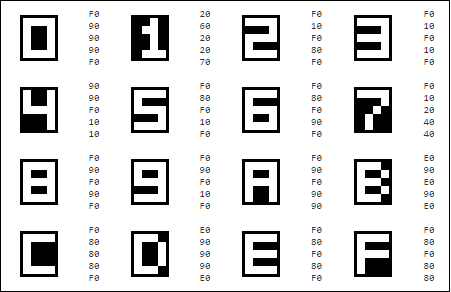
This table in C:
unsigned char chip8_fontset[80] = { 0xF0, 0x90, 0x90, 0x90, 0xF0, // 0 0x20, 0x60, 0x20, 0x20, 0x70, // 1 0xF0, 0x10, 0xF0, 0x80, 0xF0, // 2 0xF0, 0x10, 0xF0, 0x10, 0xF0, // 3 0x90, 0x90, 0xF0, 0x10, 0x10, // 4 0xF0, 0x80, 0xF0, 0x10, 0xF0, // 5 0xF0, 0x80, 0xF0, 0x90, 0xF0, // 6 0xF0, 0x10, 0x20, 0x40, 0x40, // 7 0xF0, 0x90, 0xF0, 0x90, 0xF0, // 8 0xF0, 0x90, 0xF0, 0x10, 0xF0, // 9 0xF0, 0x90, 0xF0, 0x90, 0x90, // A 0xE0, 0x90, 0xE0, 0x90, 0xE0, // B 0xF0, 0x80, 0x80, 0x80, 0xF0, // C 0xE0, 0x90, 0x90, 0x90, 0xE0, // D 0xF0, 0x80, 0xF0, 0x80, 0xF0, // E 0xF0, 0x80, 0xF0, 0x80, 0x80 // F }; Taken from here .
FX33 - Save register values in binary decimal format to I, I + 1 and I + 2.
See: Binary Decimal Code (approx. BCD translation - Binary-Coded Decimal)
Registers and memory
FX55 - Save V0 to VX register values into memory starting address I.
After execution, the register I will be equal to I + X + 1. Although some interpreters ignore this rule.
FX65 - Load registers V0 to VX inclusive of the values stored in memory starting at address I.
After execution, the register I will be equal to I + X + 1. Although some interpreters ignore this rule.
All the rest
At what frequency does the interpreter work?
About this I can not find anything in the original. The most different frequencies were obtained from the Internet: 1000Hz, 840Hz , 540Hz , 500Hz, even 60Hz.
What happens if the jump is not aligned?
I did not find any information about this, but I think that the instruction will be loaded and executed.
What will happen if you read or write from the first 512 bytes?
Nothing found again. I think it is necessary to give 0 and ignore when writing.
the end
At this end. When typos write to private messages. I would welcome any comments. The practical part is in the process of creation. The practical part will be in C (not C ++) and SDL2.
Here you can find the original. Some more info here . Another practical tutorial here .
')
Source: https://habr.com/ru/post/316788/
All Articles