Connection of peripheral modules to MIPSfpga, for example, ultrasonic distance sensors
Good day. In this article I will explain how to integrate the modules, using the example of two ultrasonic sensors HC-SR04 and Pmod MAXSONAR, into a system on a chip based on MIPSfpga. I will also tell you how to write a program for managing connected modules.
Based on my example, you can connect your own modules and manage them with the help of the program. Create a system with its own set of peripherals, based on MIPSfpga.
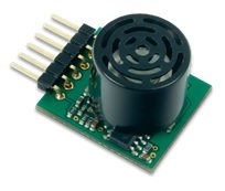
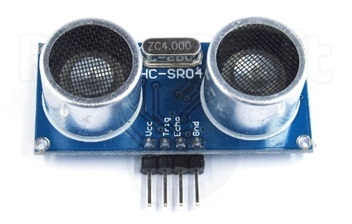
We will connect this sensor:
')
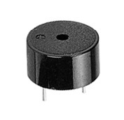
Documentation for it can be found here . Data will be displayed on the seven-segment indicators on the board. We will also generate sound signals of various duration using piezo-dynamics.
For starters, you need the MIPSfpga sources.
Instructions for downloading:
→ www.silicon-russia.com/2015/12/11/mipsfpga-download-instructions
Next, you need to download the MIPSfpga-plus add-on, which allows you to write programs on the UART:
→ github.com/MIPSfpga/mipsfpga-plus
The description and installation instructions are present, in short, in order to be able to just run the script and the project is assembled, you need:
Place the MIPSfpga source in the folder:
And MIPSfpga-plus in:
Next, in the folder C: \ github \ mipsfpga-plus \ boards, select your board, for me it is de0_cv, and execute the make_project script. The project that you want to run will be in C: \ github \ mipsfpga-plus \ boards \ de0_cv \ project .
If your card does not exist, then you can select the most suitable by the number of logical cells and change the destination.
You will also need a compiler, linker Codescape . And USB UART converter. For example, pl2303hx or ch340.
The sensor has an analog output, pulse-width modulation output, a serial interface UART, which we will use to connect the sensor to the MIPSfpga. The connection is made by connecting the registers, in which data from the sensor are displayed, to the bus, through which the processor communicates with the memory.
We will use the UART receiver already described, which is used to program programs, changing only the baud_rate parameter to 9600, which is used by the sensor at such a transmission rate.
According to the datasheet [1], every 49ms, the sonar sends four bytes in ASCII format, the symbol “R” and three characters of the measured distance, in high bits ahead.
For each clock and byte_ready flag (cocked when the byte was received), we expect the character “R” - 52 in hexadecimal, then proceed to receive the next three characters. On receiving three bytes, write lower nibbles to the output register, thus transferring from ASCII to binary-decimal format.
The module for controlling piezo-dynamics consists of two, in the first, pulses are actually generated with the possibility of selecting a frequency:
Count to div and invert the output signal. The div is chosen as input notein.
Div = Fclk / Fnote / 2
Where Fclk is the clock frequency, Fnote is the desired frequency of the output signal.
And the module where the duration of the sound pulses is regulated:
Each tick counter is incremented, when the div value is reached, the beep is enabled, when div1 is reached, it is disabled. This sets the duration and frequency of the audio signals. Also, the counter is limited to 60000000 to prevent a long pulse, which can occur when changing div1 at the moment when the value of the counter is between div and div1.
In the file mfp_ahb_lite_matrix_config.vh which is located in the folder C: \ github \ mipsfpga-plus .
Add the following lines:
Actually this is the address at which registers will be available.
Sources of modules and modified files are available here:
→ github.com/Denis-Kingit/UltraSonicToMIPSfpga
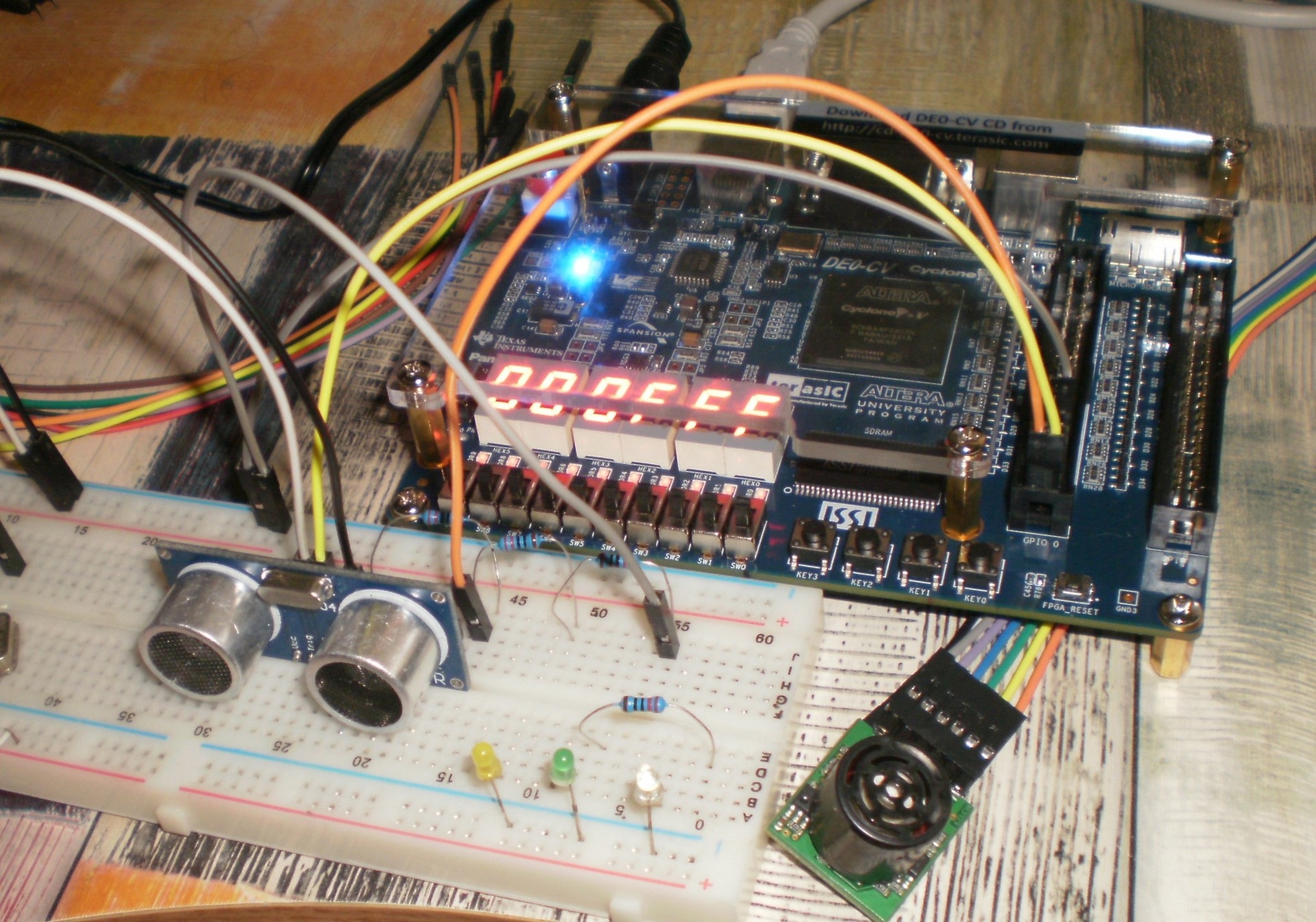
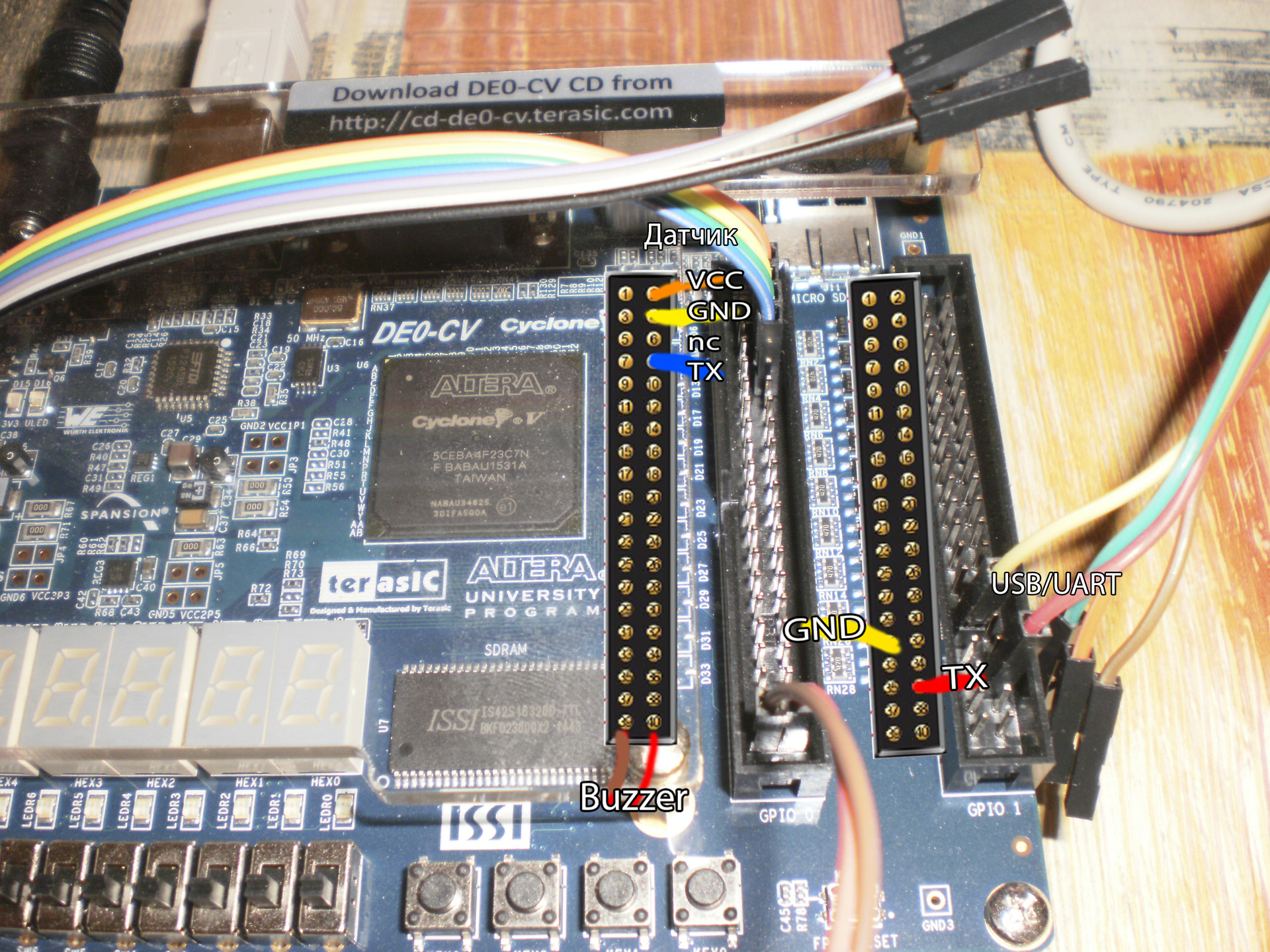
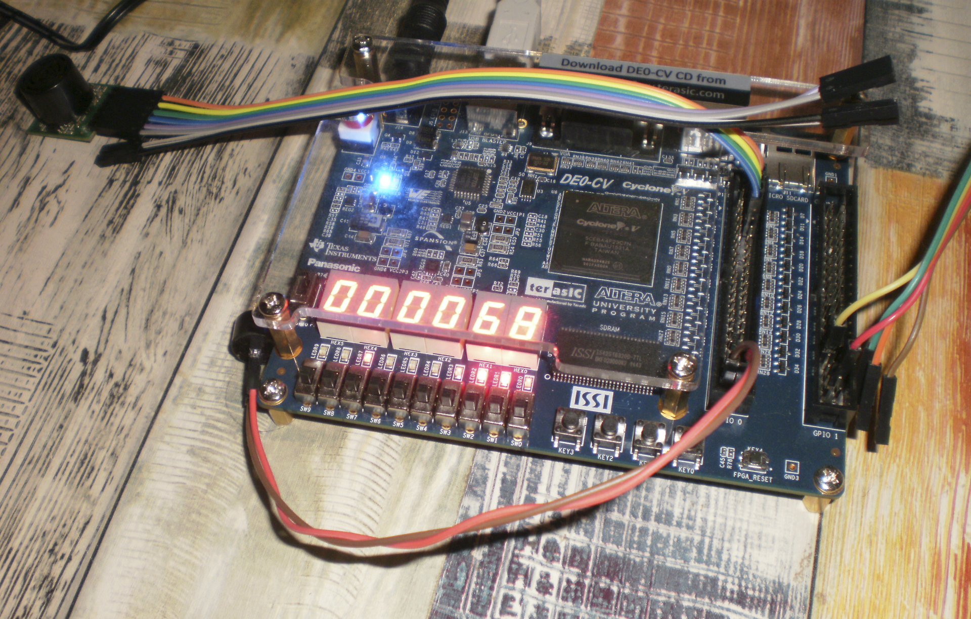
Next, we compile the project and flash the board. Connect the sensor, transducer, piezo:
Pin GND converter to GPIO_1 [26] , pin TX to GPIO_1 [31] . Pyezodinamik to GPIO_0 [34] , GPIO_0 [35] . Pin GND sensor to GPIO_0 [3] , VCC - GPIO_0 [1], TX - GPIO_0 [7] . It turns out something like:
Copy the contents of the folder C: \ github \ mipsfpga-plus \ programs \ 01_light_sensor or simply work in it. Add the following registers to the mfp_memory_mapped_registers.h file:
Now we will write a program in which we will read the values from the register and output them to the seven-segment indicators. And depending on the read value, it is controlled by a sound signal. Change main.c:
Compile by running the script:
Generate the motorola_s_record file:
Check to which COM port the USB UART converter is connected:
Modify the 12_upload_to_the_board_using_uart file:
where a is the number of the COM port to which the USB UART converter is connected.
Finally, download the program:
The idea of the connection is the same, we display the data from the sensor to the registers connected to the bus.
To measure the distance, it is necessary to apply a pulse with a duration of 10 μs to the signal Trig pin, after which the ultrasound module will emit eight packets of an ultrasonic signal with a frequency of 40 kHz and detect echo.
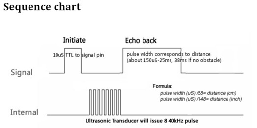
The measured distance to the object is proportional to the width of the echo, which is encoded by the duration of the electrical signal at the output of the sensor (Echo). The recommended period between measurements is at least 50ms. In order to calculate the distance, it is necessary to divide the pulse duration (echo) in microseconds by 58 for the distance in centimeters or by 148 for the distance in inches. If no obstacles are detected, then the output will be a signal with a duration of 38ms [2].
With a period of 2500000 cycles (50ms), we create a pulse at the output of trig with a duration of 500 cycles (10 μs), count the echo duration, divide by 2900 (by 50 for conversion to microseconds and by 58 for conversion to centimeters) and write the result to the register (for If you do not create an additional divider, you can translate it programmatically)) if the pulse duration is greater than 36ms, write 0xFFF, which means that no obstacles were detected.
We connect the module in the project’s top level file ( de0_cv.v ).
Similarly, we modify the files: mfp_ahb_gpio_slave.v, mfp_ahb_lite_matrix.v, mfp_ahb_lite_matrix_with_loader.v, mfp_ahb_lite_matrix_config.vh, mfp_system.v in the folder C: \ gith_matrix_config.vh, mfp_system.v in the folder folder C: \ gith_matrix_config.vh, mfp_site.vb, mfp_ahb_lite.v
To connect the sensor, you will need a 5V power supply, the trig pin is connected to GPIO_0 [33], since the sensor operates from 5V, the echo pin must be connected via a voltage divider to GPIO_0 [32], we connect the common wire of the source, sensor and board.
We write the program:
We read the values from the register, depending on the received value we control the duration of the sound, output the distance value to the seven-segment indicators.
You also need to add a new address to the mfp_memory_mapped_registers.h file .
As described above, you can connect your own modules, and manage them programmatically.
Based on my example, you can connect your own modules and manage them with the help of the program. Create a system with its own set of peripherals, based on MIPSfpga.
We will connect this sensor:
')
Documentation for it can be found here . Data will be displayed on the seven-segment indicators on the board. We will also generate sound signals of various duration using piezo-dynamics.
For starters, you need the MIPSfpga sources.
Instructions for downloading:
→ www.silicon-russia.com/2015/12/11/mipsfpga-download-instructions
Next, you need to download the MIPSfpga-plus add-on, which allows you to write programs on the UART:
→ github.com/MIPSfpga/mipsfpga-plus
The description and installation instructions are present, in short, in order to be able to just run the script and the project is assembled, you need:
Place the MIPSfpga source in the folder:
C:\MIPSfpga And MIPSfpga-plus in:
C:\github\mipsfpga-plus Next, in the folder C: \ github \ mipsfpga-plus \ boards, select your board, for me it is de0_cv, and execute the make_project script. The project that you want to run will be in C: \ github \ mipsfpga-plus \ boards \ de0_cv \ project .
If your card does not exist, then you can select the most suitable by the number of logical cells and change the destination.
You will also need a compiler, linker Codescape . And USB UART converter. For example, pl2303hx or ch340.
The sensor has an analog output, pulse-width modulation output, a serial interface UART, which we will use to connect the sensor to the MIPSfpga. The connection is made by connecting the registers, in which data from the sensor are displayed, to the bus, through which the processor communicates with the memory.
We describe the module that will receive and process data from the sensor.
We will use the UART receiver already described, which is used to program programs, changing only the baud_rate parameter to 9600, which is used by the sensor at such a transmission rate.
Uart receiver module
module uart_receiver ( input clock, input reset_n, input rx, output reg [7:0] byte_data, output byte_ready ); parameter clock_frequency = 50000000; parameter baud_rate = 9600; localparam clock_cycles_in_symbol = clock_frequency / baud_rate; // Synchronize rx input to clock reg rx_sync1, rx_sync; always @(posedge clock or negedge reset_n) begin if (! reset_n) begin rx_sync1 <= 1; rx_sync <= 1; end else begin rx_sync1 <= rx; rx_sync <= rx_sync1; end end // Finding edge for start bit reg prev_rx_sync; always @(posedge clock or negedge reset_n) begin if (! reset_n) prev_rx_sync <= 1; else prev_rx_sync <= rx_sync; end wire start_bit_edge = prev_rx_sync & ! rx_sync; // Counter to measure distance between symbols reg [31:0] counter; reg load_counter; reg [31:0] load_counter_value; always @(posedge clock or negedge reset_n) begin if (! reset_n) counter <= 0; else if (load_counter) counter <= load_counter_value; else if (counter != 0) counter <= counter - 1; end wire counter_done = counter == 1; // Shift register to accumulate data reg shift; reg [7:0] shifted_1; assign byte_ready = shifted_1 [0]; always @ (posedge clock or negedge reset_n) begin if (! reset_n) begin shifted_1 <= 0; end else if (shift) begin if (shifted_1 == 0) shifted_1 <= 8'b10000000; else shifted_1 <= shifted_1 >> 1; byte_data <= { rx, byte_data [7:1] }; end else if (byte_ready) begin shifted_1 <= 0; end end reg idle, idle_r; always @* begin idle = idle_r; shift = 0; load_counter = 0; load_counter_value = 0; if (idle) begin if (start_bit_edge) begin load_counter = 1; load_counter_value = clock_cycles_in_symbol * 3 / 2; idle = 0; end end else if (counter_done) begin shift = 1; load_counter = 1; load_counter_value = clock_cycles_in_symbol; end else if (byte_ready) begin idle = 1; end end always @ (posedge clock or negedge reset_n) begin if (! reset_n) idle_r <= 1; else idle_r <= idle; end endmodule According to the datasheet [1], every 49ms, the sonar sends four bytes in ASCII format, the symbol “R” and three characters of the measured distance, in high bits ahead.
Sonar module
module sonn ( input clock, input reset_n, input rx, output reg [15:0] hword ); reg [1:0] count2; wire [7:0] byte_data; reg [31:0] wordd; always @(posedge clock) if (! reset_n) wordd <= 32'b0; else if (byte_ready) case(count2) 2'd0:begin wordd[31:24]<=byte_data; if(byte_data==8'h52) count2<=2'd1; end 2'd1:begin wordd[23:16]<=byte_data; count2<=2'd2;end 2'd2:begin wordd[15:8]<=byte_data; count2<=2'd3;end 2'd3:begin wordd[7:0]<=byte_data; count2<=2'd0; hword={4'b0000,wordd[19:16],wordd[11:8],wordd[3:0]};end default begin wordd[31:24]<=byte_data; if(byte_data==8'h52) count2<=count2+1'b1; end endcase uart_receiver uart(clock,reset_n,rx,byte_data,byte_ready); endmodule For each clock and byte_ready flag (cocked when the byte was received), we expect the character “R” - 52 in hexadecimal, then proceed to receive the next three characters. On receiving three bytes, write lower nibbles to the output register, thus transferring from ASCII to binary-decimal format.
The module for controlling piezo-dynamics consists of two, in the first, pulses are actually generated with the possibility of selecting a frequency:
Tone module
module note(clk,reset_n,notein,noteout); input clk,reset_n; input [6:0]notein; output reg noteout; reg [19:0]div; reg [19:0]cnt; reg eocnt; always @* begin case (notein) 0: div = 191114; // C 1: div = 180385; // C# 2: div = 170262; // D 3: div = 160705; // D# 4: div = 151686; // E 5: div = 143173; // F 6: div = 135136; // F# 7: div = 127552; // G 8: div = 120389; // G# 9: div = 113636; // A 10:div = 107259; // A# 11:div = 101239; // H 12:div = 95558; // C 13:div = 90194; // C# 14:div = 85132; // D 15:div = 80354; // D# 16:div = 75845; // E 17:div = 71558; // F 18:div = 67567; // F# 19:div = 63775; // G 20:div = 60197; // G# 21:div = 28403; // A 22:div = 53629; // A# 23:div = 50619; // H 24:div = 47777; // C 25:div = 45097; // C# 26:div = 42566; // D 27:div = 40176; // D# 28:div = 37921; // E default: div = 1; // endcase end always @(posedge clk) begin if(~reset_n) begin noteout<=0; cnt <= 0; end if(cnt == div) begin cnt <= 0; noteout <= ~noteout; end else cnt <= cnt + 1'b1; end endmodule Count to div and invert the output signal. The div is chosen as input notein.
Div = Fclk / Fnote / 2
Where Fclk is the clock frequency, Fnote is the desired frequency of the output signal.
And the module where the duration of the sound pulses is regulated:
Buzz module
module buzz(clk,reset_n,en,tim,tone); input clk,reset_n,en; input [1:0]tim; output reg tone; wire [6:0]notein; wire noteout; assign notein=21; reg [27:0]counter,div,div1; reg ene; note note1(clk,reset_n,notein,noteout); always@(posedge clk) if(~reset_n) begin counter<=28'b0; ene<=1'b0; end else begin case(tim) 0:begin div<=28'd 5_000_000; div1<=28'd 12_000_000; end 1:begin div<=28'd 10_000_000; div1<=28'd 20_000_000; end 2:begin div<=28'd 25_000_000; div1<=28'd 35_000_000; end 3:begin div<=28'd 50_000_000; div1<=28'd 60_000_000; end default begin div<=28'd 10_000_000; div1<=28'd 20_000_000; end endcase counter<=counter+1; if(counter==div) ene<=1'b1; if(counter==div1 | counter>60_000_000) begin counter<=28'b0; ene<=1'b0; end end always@(posedge clk) tone<=en¬eout&ene; endmodule Each tick counter is incremented, when the div value is reached, the beep is enabled, when div1 is reached, it is disabled. This sets the duration and frequency of the audio signals. Also, the counter is limited to 60000000 to prevent a long pulse, which can occur when changing div1 at the moment when the value of the counter is between div and div1.
We connect to the project files with the modules described above.
- In my top-level file, this is de0_cv.v; we add the following lines:
wire [15:0]hword; wire [31:0]control; sonn sonna ( .clock ( CLOCK_50 ), .reset_n ( RESET_N ), .rx ( GPIO_0[7] ), .hword ( hword ) ); buzz buzz ( .clk ( CLOCK_50 ), .reset_n ( RESET_N ), .en (control [0] ), .tim (control [2:1] ), .tone ( GPIO_0[35] ) );
For the receiver RX UART input, select the GPIO_0 pin [7] and for the tone GPIO_0 [35] output. Registers hword and control will be connected to the bus.assign GPIO_0 [1] = 1'b1; //VCC for Sensor assign GPIO_0 [3] = 1'b0; //GND for Sensor assign GPIO_0 [34] = 1'b0; //GND for buzz
Select the legs GPIO_0 [1], GPIO_0 [3], GPIO_0 [34] to power the sensor, common wire for the sensor and piezo-dynamics, respectively.
In the description of the module mfp_system add:.IO_Sonar ( hword ), .IO_control ( control ), - In the file mfp_system.v we add the inputs to the outputs:
input [15:0] IO_Sonar, output [31:0] IO_control,
In the description of the module mfp_ahb_lite_matrix_with_loader:.IO_Sonar ( IO_Sonar ), .IO_control ( IO_control ), - In the file mfp_ahb_lite_matrix_with_loader.v:
input [15:0] IO_Sonar, output [31:0] IO_control,
In the description of the module mfp_ahb_lite_matrix:.IO_Sonar ( IO_Sonar ), .IO_control ( IO_control ), - In the file mfp_ahb_lite_matrix.v:
input [15:0] IO_Sonar, output [31:0] IO_control,
In the description of the module mfp_ahb_gpio_slave.IO_Sonar ( IO_Sonar ), .IO_control ( IO_control) - In the file mfp_ahb_gpio_slave.v:
input [15:0]IO_Sonar, output reg[31:0]IO_control,
in the last but one by! HRESETnIO_control <=32'b0;
And in case (write_ionum)`MFP_CONTROL_IONUM : IO_control <=HWDATA;
In the last always in case (read_ionum)`MFP_SONAR_SENSOR_IONUM : HRDATA = { 16'b0, IO_Sonar };
In the file mfp_ahb_lite_matrix_config.vh which is located in the folder C: \ github \ mipsfpga-plus .
Add the following lines:
`define MFP_SONAR_SENSOR_IONUM 4'h6 `define MFP_CONTROL_IONUM 4'h9 `define MFP_SONAR_SENSOR_ADDR 32'h1f800018 `define MFP_CONTROL_ADDR 32'h1f800024 Actually this is the address at which registers will be available.
Sources of modules and modified files are available here:
→ github.com/Denis-Kingit/UltraSonicToMIPSfpga
Next, we compile the project and flash the board. Connect the sensor, transducer, piezo:
Pin GND converter to GPIO_1 [26] , pin TX to GPIO_1 [31] . Pyezodinamik to GPIO_0 [34] , GPIO_0 [35] . Pin GND sensor to GPIO_0 [3] , VCC - GPIO_0 [1], TX - GPIO_0 [7] . It turns out something like:
Software part
Copy the contents of the folder C: \ github \ mipsfpga-plus \ programs \ 01_light_sensor or simply work in it. Add the following registers to the mfp_memory_mapped_registers.h file:
#define MFP_SONAR_SENSOR_ADDR 0xBF800018 #define MFP_CONTROL_ADDR 0xBF800024 #define MFP_SONAR_SENSOR (* (volatile unsigned *) MFP_SONAR_SENSOR_ADDR ) #define MFP_CONTROL (* (volatile unsigned *) MFP_CONTROL_ADDR ) Now we will write a program in which we will read the values from the register and output them to the seven-segment indicators. And depending on the read value, it is controlled by a sound signal. Change main.c:
Program
#include "mfp_memory_mapped_registers.h" int main () { MFP_CONTROL = 1; for (;;) { MFP_7_SEGMENT_HEX = MFP_SONAR_SENSOR; if(MFP_SONAR_SENSOR<0x10) MFP_CONTROL = 1; else if (MFP_SONAR_SENSOR<0x12) MFP_CONTROL = 3; else if (MFP_SONAR_SENSOR<0x14) MFP_CONTROL = 5; else if (MFP_SONAR_SENSOR<0x16) MFP_CONTROL = 7; else MFP_CONTROL = 0; } return 0; } Compile by running the script:
02_compile_and_link Generate the motorola_s_record file:
08_generate_motorola_s_record_file Check to which COM port the USB UART converter is connected:
11_check_which_com_port_is_used Modify the 12_upload_to_the_board_using_uart file:
set a=7 mode com%a% baud=115200 parity=n data=8 stop=1 to=off xon=off odsr=off octs=off dtr=off rts=off idsr=off type program.rec >\.\COM%a% where a is the number of the COM port to which the USB UART converter is connected.
Finally, download the program:
12_upload_to_the_board_using_uart Now connect Ultrasonic HC-SR04
The idea of the connection is the same, we display the data from the sensor to the registers connected to the bus.
To measure the distance, it is necessary to apply a pulse with a duration of 10 μs to the signal Trig pin, after which the ultrasound module will emit eight packets of an ultrasonic signal with a frequency of 40 kHz and detect echo.
The measured distance to the object is proportional to the width of the echo, which is encoded by the duration of the electrical signal at the output of the sensor (Echo). The recommended period between measurements is at least 50ms. In order to calculate the distance, it is necessary to divide the pulse duration (echo) in microseconds by 58 for the distance in centimeters or by 148 for the distance in inches. If no obstacles are detected, then the output will be a signal with a duration of 38ms [2].
Sonic module
module sonic(clk,trig,reset_n,en,echo,out); input clk,echo,reset_n,en; output reg trig; output reg[23:0]out; reg [23:0]count; reg [23:0]countp; always@(posedge clk) if(~reset_n) begin countp<=24'b0; count<=24'b0; end else if(en) begin if(countp==0) trig<=1'b1; if(echo) count<=count+1'b1; if(countp==500) trig<=1'b0; if(countp==2500000) begin if (count>1800000) out<=24'hfff; else out<=count/2900; countp<=24'b0; count<=24'b0; end countp<=countp+1'b1; end endmodule With a period of 2500000 cycles (50ms), we create a pulse at the output of trig with a duration of 500 cycles (10 μs), count the echo duration, divide by 2900 (by 50 for conversion to microseconds and by 58 for conversion to centimeters) and write the result to the register (for If you do not create an additional divider, you can translate it programmatically)) if the pulse duration is greater than 36ms, write 0xFFF, which means that no obstacles were detected.
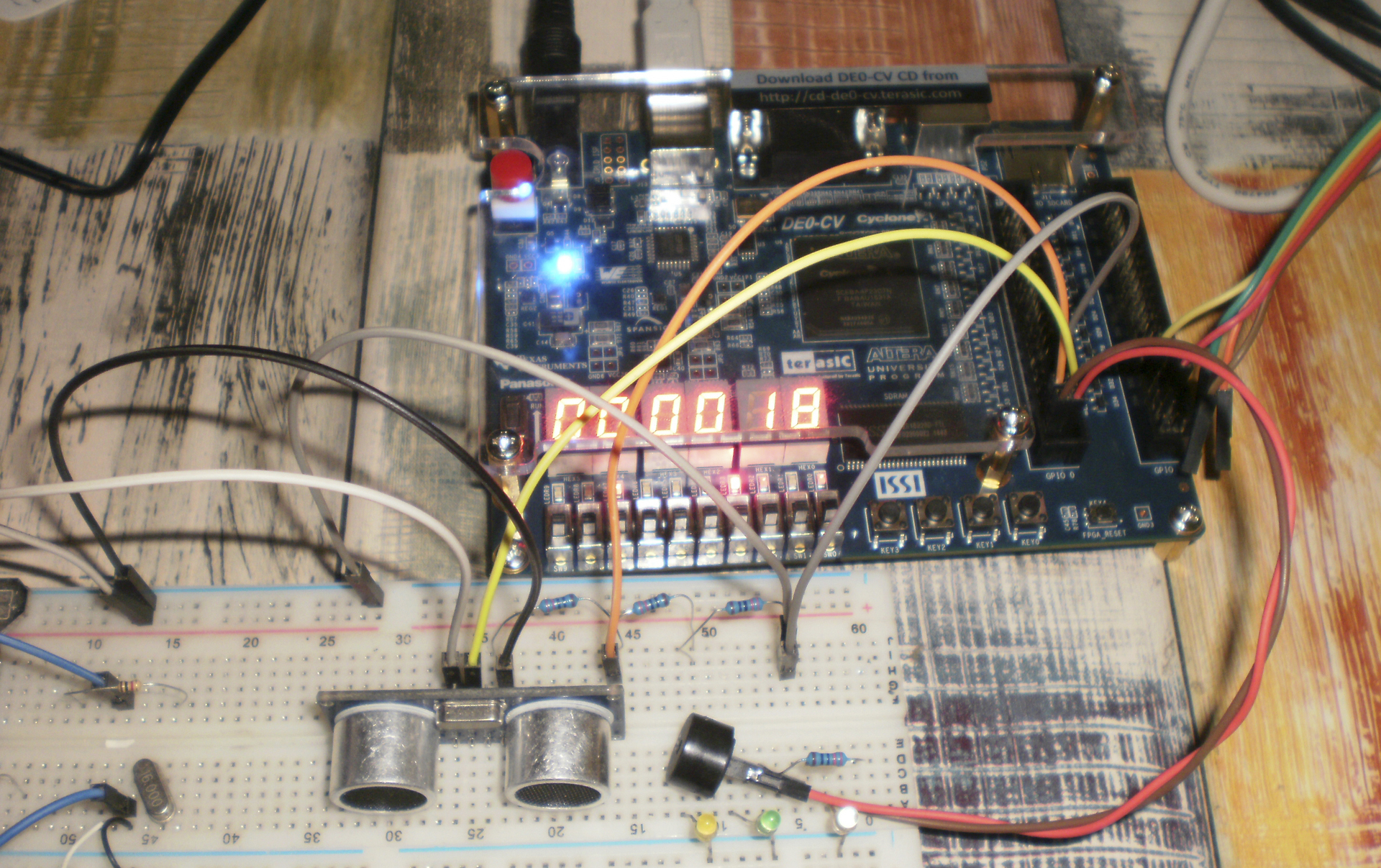
We connect the module in the project’s top level file ( de0_cv.v ).
wire [23:0] usonic; sonic sonica ( .clk ( CLOCK_50 ), .trig ( GPIO_0[33] ), .reset_n ( RESET_N ), .en ( control[3] ), .echo ( GPIO_0[32] ), .out ( usonic ) ); Similarly, we modify the files: mfp_ahb_gpio_slave.v, mfp_ahb_lite_matrix.v, mfp_ahb_lite_matrix_with_loader.v, mfp_ahb_lite_matrix_config.vh, mfp_system.v in the folder C: \ gith_matrix_config.vh, mfp_system.v in the folder folder C: \ gith_matrix_config.vh, mfp_site.vb, mfp_ahb_lite.v
To connect the sensor, you will need a 5V power supply, the trig pin is connected to GPIO_0 [33], since the sensor operates from 5V, the echo pin must be connected via a voltage divider to GPIO_0 [32], we connect the common wire of the source, sensor and board.
We write the program:
Program
#include "mfp_memory_mapped_registers.h" int main () { int k = 0; for (;;) { //MFP_RED_LEDS = MFP_SONICR_SENSOR >> 4; k=MFP_SONIC_SENSOR/58/50; MFP_7_SEGMENT_HEX = k; if(k<0x10) MFP_CONTROL = 1; else if (k<0x12) MFP_CONTROL = 3; else if (k<0x14) MFP_CONTROL = 5; else if (k<0x16) MFP_CONTROL = 7; else MFP_CONTROL = 0; } return 0; } We read the values from the register, depending on the received value we control the duration of the sound, output the distance value to the seven-segment indicators.
You also need to add a new address to the mfp_memory_mapped_registers.h file .
#define MFP_SONIC_SENSOR_ADDR 0xBF800020 #define MFP_SONIC_SENSOR (* (volatile unsigned *) MFP_SONIC_SENSOR_ADDR ) As described above, you can connect your own modules, and manage them programmatically.
useful links
[1] LV-MaxSonar - maxbotix.com/documents/LV-MaxSonar-EZ_Datasheet.pdf
[2] Ultrasonic HC SR04 - robocraft.ru/blog/electronics/772.html
Sources MIPSfpga-plus github.com/MIPSfpga/mipsfpga-plus
Codescape - Codescape
Instructions for downloading mipsfpga - Instructions
Sources of modules, programs and modified files:
github.com/Denis-Kingit/UltraSonicToMIPSfpga
Just a useful book - David Harris and Sarah Harris "Digital Circuit Design and Computer Architecture"
Source: https://habr.com/ru/post/316770/
All Articles