FPGA Debug Board - Frankenstein. Clock. Altera EPM7064 VS Lattice LC4064v
Continuation of the pre-New Year series of adventures of a small FPGA Altera EPM7064 on a debug board - Frankenstein. In the previous series ...
 It is time to compare two FPGAs from the same weight category: Altera EPM7064 and Lattice LC4064v . Although, one of them - only weight - is 64 macro cells. Otherwise, judging by the parameters, these FPGAs have completely different purposes. The FPGA from Altera, judging by the documentation of 2005, is simply not young, from which it has a low number of cells. It also has a popular for those times supply voltage - 5 volts. The maximum operating frequency does not exceed 200 MHz. At the same time, Lattice can operate up to 400 MHz frequencies, but at the same time, it is powered by a voltage of 3.3 volts. Yes, this is not as convenient as 5 volts if we want to interact with the old circuits (however, tolerance to 5V is claimed). The documentation for Lattice of this series indicates 2014, so I will assume that these are modern high-speed FPGAs, but of small volume, and judging by the "SuperFAST CPLD" in the description, they are positioned somewhat differently.
How do we compare them? Let's try to solve the same problem on them. We already tried to make the clock on Lattice LC4064v and we did it. Now let's try to make a clock on the Altera EPM7064 - on our Frankenstein.
Indicator
The fee is ready with us, so we need to add an indicator to it. Naturally dynamic. For the purity of the experiment, of course, one would have to apply the same indicator as on Lattice (or identical). But I don’t have the same thing, but I consider it a bad habit to remove parts from working devices. Therefore, I took another indicator suitable for the manufacture of watches, which I was recently presented to.
It looks quite like this one, but it has another pinout.
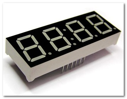
I could not find her. I see no point in describing it, because There are many such screens and they can be different. Using the tester, you can easily set pin assignments. And with the help of a prototyping board and my favorite wrap-around mounting technology, I ordered the sequence of indicator pins (1-2-3-4, ABCDEFG).
In the Lattice clock I used transistors to unload the lines that select groups. Immediately, I decided not to do anything about it, but to connect the LEDs directly to the FPGAs, even without using current-limiting resistors (in general this is not the right thing to do). The logic is approximately as in this figure:
As a result, the test configuration displayed the numbers 1-2-3-4. LEDs are bright enough. FPGA is almost not heated. I hope Frankie will live to light days and will not fail from such a load. And in order to reduce this probability, we will reduce the period during which the indicators will be turned on, thereby reducing the indicator brightness.
In general, the code is all the same, except for the logic output to the screen.
module epm7064_clock(clk, dig_sel, segs, btn_HH, btn_MM, btn_SS, btn_SAFE, led_second_tick); ... output wire [3:0] dig_sel; // output wire [6:0] segs; // ... // , - // // , 1/4 . // 0001 -> 0010 -> 0100 -> 1000 wire [3:0] top_bits = clk_div[6:3]; // wire [4:0] t_dig_sel = (top_bits == 4'b0000 && h_show &&(!SAFE_MODE)) ? 4'b0001 : (top_bits == 4'b0100 &&(!SAFE_MODE)) ? 4'b0010 : (top_bits == 4'b1000 &&(!SAFE_MODE)) ? 4'b0100 : (top_bits == 4'b1100 &&(!SAFE_MODE)) ? 4'b1000 : 4'b0000; // // , ... bcd2seg0_2 sseg_1( .sin(hh), .sout(s_m1)); bcd2seg0_9 sseg_2( .sin(h), .sout(s_m2)); bcd2seg0_5 sseg_3( .sin(mm), .sout(s_m3)); bcd2seg0_9 sseg_4( .sin(m), .sout(s_m4)); wire [6:0] t_segs = (top_bits == 4'b0000) ? ~s_m1 : (top_bits == 4'b0100) ? ~s_m2 : (top_bits == 4'b1000) ? ~s_m3 : (top_bits == 4'b1100) ? ~s_m4 : 7'b0000000; ... // 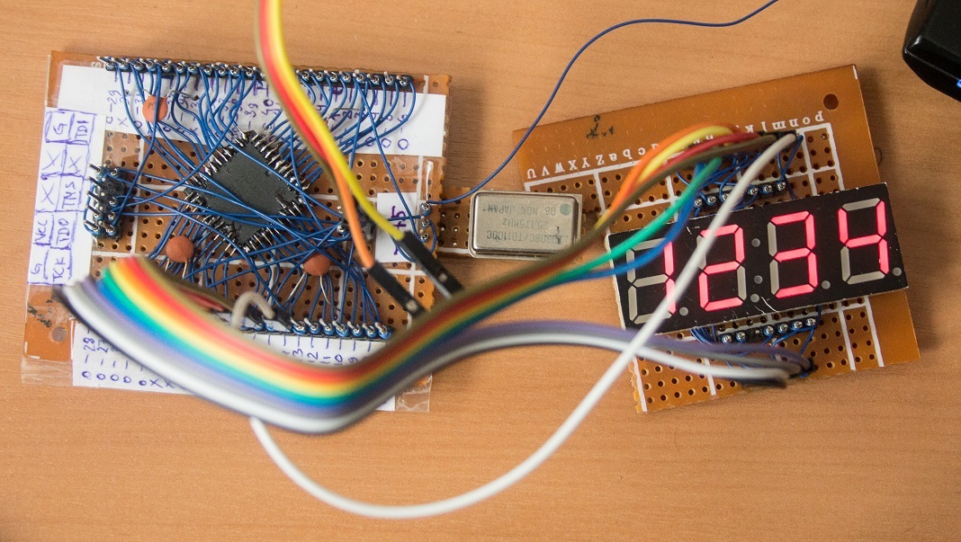
Full project - https://github.com/UA3MQJ/epm7064_clock
Clock generator
In hours on Lattice I tried to start the generator on the logical elements of the FPGA itself. This time I also tried to start the generator, only on Altera. There are mentions in the network that the generators were successfully launched on max and even on cyclone . But I did not manage to start the generator at 32768. Maybe this quartz failed, or I spoiled it in the process of experiments, or the parameters are wrong. I tried both the circuit with one inverter, and with two. Inverters took both buffer and without. In general, the whole weekend was wasted, the generator could not be started.
 In general, it is believed that such generators are a bad idea. Ready-made generators are more stable, development is faster. On the other hand, those who managed to calculate everything correctly and stably start the generator on the FPGA use this solution.
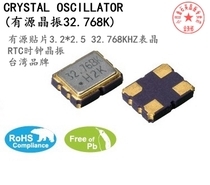
In the meantime, I could not start the generator, I will wait, maybe my comrade can do it. In the meantime, I'll order a 32.768KHz OSC Active Crystal Oscillator.
The scheme from [1] for some reason did not work either. Rather, the generation was there, but the amplitude was small, and the stability of the waveform was not enough for my oscilloscope to synchronize with it. Perhaps, all the same, the problem with a specific quartz.
For verification, you can use the Lattice clock generator, which we will do
findings
Inside the Altera FPGA, we implemented the same logic, with the exception of the output to the LED screen (because it is of a different type). It is interesting to note that the Altera FPGA consumed resources amounted to 61 cells, while Lattice spent 59. I think that the reason is just in different screens. At Lattice, 16 lines are used to control the screen, and 11 lines are required for the screen on Altera. Perhaps a smaller number of lines turned harder to decipher. So we can assume that they have equal synthesizers and hardware capabilities. The output current of Altera is slightly higher, and a different type of screen, so we managed to do without additional transistors, and the LED indicator was connected and started working directly.
The current consumption of Altera EPM7064 averaged 100 mA and 66 mA in safe_mode (excluding generator current 32768 Hz), while Lattice consumes 125 mA at 3.3 volts. Consumption of approximately the same order. In general, power from 5 volts is more convenient. However, in this project it is only a matter of a voltage regulator, since there is no interaction with other chips of five-volt logic. Therefore, there is no advantage over 3.3V power supply either.
The generator on 32768 could not be collected either on Lattice or on Altera. I am convinced that the generator can be built, in this project such a hardware hack would be very effective, but it did not work out.
And we will not linger, because we want to see Frankie in other projects!
List of used sources
')
Source: https://habr.com/ru/post/316586/
All Articles