FPGA Debug Board - Frankenstein. Telegraph transmitter
Run the last days of the year. New Year's bustle. And for those who have had a free minute at work, I propose a series of articles about self-made debug board based on the Altera EPM 7064 FPGA.

Recently, I needed to find a pair of 1U cases for my project. And as an alternative to the new one, we decided to look for old devices in 1U format , discard the insides, and use the case for its intended purpose. But, opening the case, I was pleasantly surprised! As many as four FPGAs from Altera , and besides, 5 volts. I could not resist not to try one of them in action!
')
I do not have a soldering station, I do not practice LUT technology. Therefore, I took a building dryer at 250 degrees and otkovyryal FPGA chip from the board. I didn’t have a transition board for such a case either, so I took the usual breadboard, soldered the racks into it, and with the help of cheating and soldering, I connected the pins of the chip to the racks. Disconnected JTAG connector and power, screwed generator. This is all you need to get started with the chip.
What can be made of such a small FPGA? Radio amateurs solve such a problem very simply: in any incomprehensible situation we make transmitters! Of what? Yes, from anything that came to hand at the moment! And today we have Altera EPM7064 .
And she's all right! A huge advantage of this chip is its operating voltage of 5 volts. And this means that we have no problems with its power, we do not need to coordinate the levels when connecting it with any old TTL logic: old computers, such as the ZX Spectrum or logic circuits on discrete TTL chips.
This FPGA also stores the configuration in the built-in non-volatile memory. External flash memory chips are required.
However, its volume is not too large: only 64 cells. It is not so much. In the project on FPGA Lattice we managed to assemble a watch. There were also 64 cells. Interestingly, the same HDL scheme will fit in the FPGA of the same volume, only from Altera?

In fact, making a transmitter is very easy! It is enough to take a generator of a certain frequency and connect it to the antenna (for the time being, we will not talk about matching, the characteristic impedance of the communication line and the resonant frequency of the antenna). After that, if we have a receiver for this frequency and modulation, we can receive the signal. At short distances, clock generators can be received at the receiver even from a conventional board with a microcontroller.
If you simply turn on the transmitter-generator at a certain frequency, it will not transmit any useful information. Therefore, the transmitter signal must somehow be modulated. There are many types of modulation.
In amateur radio practice, the simplest form of communication is Telegraph (CW). Telegraph is in many ways a unique form of communication. On the one hand, it can be considered a digital form of communication, and even the very first digital form of communication. On the other hand, a trained person is able to decode this digital signal by ear. Now for this there are software decoders. But the human ear is still considered the most accurate instrument for reception. Another telegraph is one of the most "long-range" types of communication. Due to the transmission at one frequency and the low transmission rate, all signal energy concentrates on one frequency, this has a positive effect on the transmission distance. Narrowband filters can be used for reception. The telegraph signal consists of dots and dashes. Each symbol of the telegraph alphabet is a combination of dots and a dash. The most frequently used letters consist of a smaller number of elements.
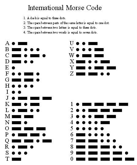
Points and dashes are the facts of switching on the transmitter. Between the dots and the dash, the transmitter is turned off, the signal is not transmitted to the air. There are rules according to which a dash should have a duration equal to three points. The gap between points or a dash in one character must be equal to the duration of one point. The gap between the letters in one word should be equal to three points. And between the words there should be a pause of at least seven points.
If we connect a wire of small length (as an antenna) to the output of the FPGA and send a clock signal to this output, we will be able to accept this signal as an unmodulated carrier frequency. By enabling and disabling the output of the signal to the antenna, we will modulate the carrier. And forming the correct time intervals for points and dashes, we will generate a telegraph radio signal.
To form time intervals in fractions of a second, we need to divide the clock signal. In my case, the frequency of the clock generator is 25175000 Hz. I decided to take a 23 bit binary counter. The frequency obtained as a result will be equal to:
It is quite enough to form an interval of one point.
Now we will try to form something very simple. For example, the signal SOS: three points, three dashes, three points. Draw a timeline:

From it we see that we need 30 steps. This is 5 bits. That is, we add another 5 bits to the 22 bits of the counter. And we get 27 bits.
Now the logic is very simple (because we can’t put complex logic into such a small FPGA): when the counter value is 0, 2, 4, 8, 9, 10 (and further on the diagram) we give a unit, otherwise - zero. This signal (CW) can already be output from the FPGA and control it, for example, by a LED. And in order to modulate the radio signal, we will output the clock signal to the output only if the value of the CW signal is one.
That's it, it's time to turn on the receiver
Unfortunately, we don’t need a broadcast receiver for our transmitter. Firstly, because of the frequency bands - such a frequency may simply not be in the broadcast receiver. Secondly because of the type of modulation. The broadcast receiver will receive in amplitude modulation (AM), therefore, when there is no telegraph signal, then the receiver will receive terrestrial noise, and when there is a carrier, there will be silence with the receiver (since the carrier is not modulated in any way by amplitude). As a result, the AM receiver will emit a noise interrupted by silence at the points of dots and dashes.
What is needed receiver? To receive the telegraph you need a single-band receiver . I will be honest, choosing the frequency I cheated a little. I have a USB receiver, the lower limit of which is 24 MHz, so I also chose the frequency of the generator, taking into account that the signal could be received at this receiver. Such a receiver can be bought on ebay / aliexpress for about 500 rubles. Search by words R820T2. As a reception program, I use SDRSharp.
A little thought, I remembered that I have a mid-wave receiver. Frequency of reception is 530 - 1600 KHz. Modulation - amplitude. Most often, the receiver for this range is in almost every car stereo. And we collected with the son such a receiver from the designer .
In order to get the carrier frequency in the frequency range of this receiver, we need to divide the frequency of the clock generator. If we take individual bits from our counter, then we just get the clock generator values divided by the power of two. For example, the 4th bit is the division by 16 and the result is 1573 KHz, I chose the 5th bit and the frequency 786 KHz (since the Chinese variable capacitor turned out to be slightly defective, and does not cover the entire frequency range).
Now we need to produce amplitude modulation of the signal. It is easier for us - we have a telegraph signal, so it is enough for us to interrupt the carrier frequency with an audible frequency. Get 100% modulation. For reception at the AM receiver (for operation of the amplitude detector in the receiver) this will be sufficient. Select the appropriate bit from the counter-frequency divider. This is the 14th bit, which is equivalent to dividing by 16384. As a result, the frequency is 1536 Hz. This frequency is in the human-audible range, and in the range of frequencies that the AM receiver is able to output.
The code on Verilog needs a little tweak:
And we got an amplitude telegraphy.
For the project were used: FPGA Altera EPM7064, Quartus II 11.1, Chinese programmer. The number of occupied cells is 30 out of 64. This means that you can complicate the project for the transfer of longer texts.
→ GitHub
Please do not worry about Frankenstein, very soon I will give the FPGA to my friend, and he will make for her a decent printed circuit board .
Continuation of the adventure Frankie wait tomorrow morning!
Recently, I needed to find a pair of 1U cases for my project. And as an alternative to the new one, we decided to look for old devices in 1U format , discard the insides, and use the case for its intended purpose. But, opening the case, I was pleasantly surprised! As many as four FPGAs from Altera , and besides, 5 volts. I could not resist not to try one of them in action!
')
I do not have a soldering station, I do not practice LUT technology. Therefore, I took a building dryer at 250 degrees and otkovyryal FPGA chip from the board. I didn’t have a transition board for such a case either, so I took the usual breadboard, soldered the racks into it, and with the help of cheating and soldering, I connected the pins of the chip to the racks. Disconnected JTAG connector and power, screwed generator. This is all you need to get started with the chip.
What can be made of such a small FPGA? Radio amateurs solve such a problem very simply: in any incomprehensible situation we make transmitters! Of what? Yes, from anything that came to hand at the moment! And today we have Altera EPM7064 .
What is wrong with Altera EPM7064?
And she's all right! A huge advantage of this chip is its operating voltage of 5 volts. And this means that we have no problems with its power, we do not need to coordinate the levels when connecting it with any old TTL logic: old computers, such as the ZX Spectrum or logic circuits on discrete TTL chips.
This FPGA also stores the configuration in the built-in non-volatile memory. External flash memory chips are required.
However, its volume is not too large: only 64 cells. It is not so much. In the project on FPGA Lattice we managed to assemble a watch. There were also 64 cells. Interestingly, the same HDL scheme will fit in the FPGA of the same volume, only from Altera?
Making a transmitter
In fact, making a transmitter is very easy! It is enough to take a generator of a certain frequency and connect it to the antenna (for the time being, we will not talk about matching, the characteristic impedance of the communication line and the resonant frequency of the antenna). After that, if we have a receiver for this frequency and modulation, we can receive the signal. At short distances, clock generators can be received at the receiver even from a conventional board with a microcontroller.
If you simply turn on the transmitter-generator at a certain frequency, it will not transmit any useful information. Therefore, the transmitter signal must somehow be modulated. There are many types of modulation.
In amateur radio practice, the simplest form of communication is Telegraph (CW). Telegraph is in many ways a unique form of communication. On the one hand, it can be considered a digital form of communication, and even the very first digital form of communication. On the other hand, a trained person is able to decode this digital signal by ear. Now for this there are software decoders. But the human ear is still considered the most accurate instrument for reception. Another telegraph is one of the most "long-range" types of communication. Due to the transmission at one frequency and the low transmission rate, all signal energy concentrates on one frequency, this has a positive effect on the transmission distance. Narrowband filters can be used for reception. The telegraph signal consists of dots and dashes. Each symbol of the telegraph alphabet is a combination of dots and a dash. The most frequently used letters consist of a smaller number of elements.
Points and dashes are the facts of switching on the transmitter. Between the dots and the dash, the transmitter is turned off, the signal is not transmitted to the air. There are rules according to which a dash should have a duration equal to three points. The gap between points or a dash in one character must be equal to the duration of one point. The gap between the letters in one word should be equal to three points. And between the words there should be a pause of at least seven points.
If we connect a wire of small length (as an antenna) to the output of the FPGA and send a clock signal to this output, we will be able to accept this signal as an unmodulated carrier frequency. By enabling and disabling the output of the signal to the antenna, we will modulate the carrier. And forming the correct time intervals for points and dashes, we will generate a telegraph radio signal.
The formation of the telegraph signal
To form time intervals in fractions of a second, we need to divide the clock signal. In my case, the frequency of the clock generator is 25175000 Hz. I decided to take a 23 bit binary counter. The frequency obtained as a result will be equal to:
counter 2 ^ 22 = 4194304
clock frequency 25175000 Hz
the resulting frequency 25175000/4194304 = 6 Hz
It is quite enough to form an interval of one point.
Now we will try to form something very simple. For example, the signal SOS: three points, three dashes, three points. Draw a timeline:
From it we see that we need 30 steps. This is 5 bits. That is, we add another 5 bits to the 22 bits of the counter. And we get 27 bits.
Now the logic is very simple (because we can’t put complex logic into such a small FPGA): when the counter value is 0, 2, 4, 8, 9, 10 (and further on the diagram) we give a unit, otherwise - zero. This signal (CW) can already be output from the FPGA and control it, for example, by a LED. And in order to modulate the radio signal, we will output the clock signal to the output only if the value of the CW signal is one.
module epm7064_test(clk, out_lf, out_rf); input wire clk; output wire out_lf; output wire out_rf; reg [27:0] cnt; initial cnt <= 28'd0; always @(posedge clk) cnt <= cnt + 1'b1; wire [4:0] hi_bits = cnt[26:26-4]; // 5 wire cw = (hi_bits == 5'd0) || (hi_bits == 5'd2) || (hi_bits == 5'd4) || (hi_bits == 5'd8) || (hi_bits == 5'd9) || (hi_bits == 5'd10) || (hi_bits == 5'd12) || (hi_bits == 5'd13) || (hi_bits == 5'd14) || (hi_bits == 5'd16) || (hi_bits == 5'd17) || (hi_bits == 5'd18) || (hi_bits == 5'd22) || (hi_bits == 5'd24) || (hi_bits == 5'd26); assign out_lf = cw; assign out_rf = cw & clk; endmodule That's it, it's time to turn on the receiver
Receive our transmitter signal
Unfortunately, we don’t need a broadcast receiver for our transmitter. Firstly, because of the frequency bands - such a frequency may simply not be in the broadcast receiver. Secondly because of the type of modulation. The broadcast receiver will receive in amplitude modulation (AM), therefore, when there is no telegraph signal, then the receiver will receive terrestrial noise, and when there is a carrier, there will be silence with the receiver (since the carrier is not modulated in any way by amplitude). As a result, the AM receiver will emit a noise interrupted by silence at the points of dots and dashes.
What is needed receiver? To receive the telegraph you need a single-band receiver . I will be honest, choosing the frequency I cheated a little. I have a USB receiver, the lower limit of which is 24 MHz, so I also chose the frequency of the generator, taking into account that the signal could be received at this receiver. Such a receiver can be bought on ebay / aliexpress for about 500 rubles. Search by words R820T2. As a reception program, I use SDRSharp.
Modify the transmitter for AM reception
A little thought, I remembered that I have a mid-wave receiver. Frequency of reception is 530 - 1600 KHz. Modulation - amplitude. Most often, the receiver for this range is in almost every car stereo. And we collected with the son such a receiver from the designer .
In order to get the carrier frequency in the frequency range of this receiver, we need to divide the frequency of the clock generator. If we take individual bits from our counter, then we just get the clock generator values divided by the power of two. For example, the 4th bit is the division by 16 and the result is 1573 KHz, I chose the 5th bit and the frequency 786 KHz (since the Chinese variable capacitor turned out to be slightly defective, and does not cover the entire frequency range).
Now we need to produce amplitude modulation of the signal. It is easier for us - we have a telegraph signal, so it is enough for us to interrupt the carrier frequency with an audible frequency. Get 100% modulation. For reception at the AM receiver (for operation of the amplitude detector in the receiver) this will be sufficient. Select the appropriate bit from the counter-frequency divider. This is the 14th bit, which is equivalent to dividing by 16384. As a result, the frequency is 1536 Hz. This frequency is in the human-audible range, and in the range of frequencies that the AM receiver is able to output.
The code on Verilog needs a little tweak:
wire audio = cnt[13]; // 14 - 1536 - wire rf = cnt[ 4]; // 5 - ~786 R - assign out_rf = cw & rf & audio; And we got an amplitude telegraphy.
Conclusion
For the project were used: FPGA Altera EPM7064, Quartus II 11.1, Chinese programmer. The number of occupied cells is 30 out of 64. This means that you can complicate the project for the transfer of longer texts.
→ GitHub
Please do not worry about Frankenstein, very soon I will give the FPGA to my friend, and he will make for her a decent printed circuit board .
Continuation of the adventure Frankie wait tomorrow morning!
Source: https://habr.com/ru/post/316234/
All Articles