Connecting the character LCD to the board from WD MyBook Live on AppliedMicro APM82181. Ending
Good day! Let's continue working with the NAS WesternDigital MyBook Live board and the LCD indicator connected to it. So, in the previous part, we found a place on the board to connect to the I2C bus, connected a port expander with an indicator, made sure everything worked. Today we will display the status of the system.
The beginning was here: Connecting a character LCD to the WD MyBook Live board on AppliedMicro APM82181
Content of the first part:
Today we consider:
')
As before, additions and comments are welcome.
So, by this moment the port extender is connected to the system, which we can control. A symbol LCD indicator on the clone of the HD44780 controller is attached to the expander. Theoretically, we can manage it by turning on all the ports on the output and knowing their purpose. It was already possible to flash the backlight, pulling the third port.
The connection between the HD44780 controller and the port expander is organized as follows:
This is one of the meeting options. The controller is translated and operates in 4-bit mode, and the byte is transmitted in parts.
Having all the ports of the expander available, it is possible to output data to it bit by bit and thus control the display. I think you will agree that this is not very convenient.
Let's try to directly control via the I2C bus. A simple option to test this possibility is to use the I2C-tools toolkit. In LEDE, they are in the Utilites section. The set includes i2cdetect, i2cdump, i2cget, i2cset. We are interested in the latter and a little first (for diagnostics).
Using i2cdetect, you can detect devices connected to the bus and determine their address.
The i2cset utility is used to output data to a device with a given address on the I2C bus.
Knowing the initialization sequence for your LCD, you can easily perform it and display characters on the screen.
In order not to reinvent the wheel, I recommend downloading it from here: I2C hd44780 module on PCF8574 expander "i2c lcd testilku". Here is the direct link . Inside the archive is a shell script that works with the indicator via the i2cset command and displays the characters alternately on the screen. The only thing to use is to comment or delete the lines at the beginning of the file:
They create the I2C software port on any free I / O ports, and we already have a hardware one. Well, and besides, it is designed for an indicator with a dimension of 4 * 40, but to test the functionality and understanding of the use of the i2cset utility, this does not hurt much.
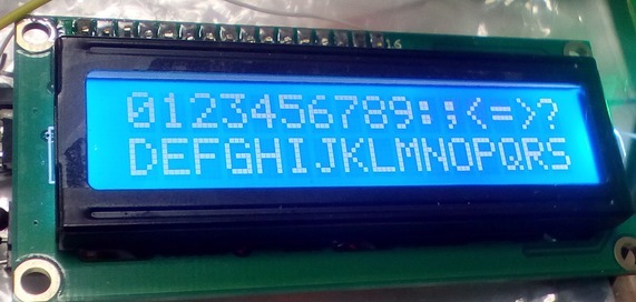
Result:
A little explanation on its implementation. The write_CMD and print_LCD procedures display, respectively, a command or data on the indicator. It depends on the RS signal, which in our case is on the zero bit.
The init_LCD procedure sequentially issues commands to initialize the indicator according to its datasheet widely used on the Internet. For example, here . Further on, various symbols are displayed on the screen.
Everything is fine, but I would like to get away from using utilities, and to have a character device, bringing to which bytes, they would fall directly on the I2C bus, of course, with a given address.
Unfortunately, I could not find such a driver for the I2C bus in LEDE. Therefore, with experimental objectives, it was decided to remake one of the existing ones. It is clear that if you want to use it further, it was necessary not to redo it, but at least create a new one on its basis.
EEPROM driver for I2C bus turned out to be suitable for experiments. The kmod-eeprom-at24 driver was connected to the LEDE core. After updating the system, an attempt was made to add a device:
Successfully connected. Now, if you bring something to the device:
then on the bus we will see the following sequence of bytes:
The first byte in each triple is the device address, multiplied by 2 (0x27 x 2). The second is the cell address in the EEPROM, the third is the data. The driver is quite suitable for transferring data to the LCD, with the exception of issuing a cell address.
To remove this, we fix the driver build_dir / target-powerpc_464fp_musl-1.1.15 / linux-apm821xx_sata / linux-4.4.21 / drivers / misc / eeprom / at24.c driver file. Comment out a few lines in the at24_eeprom_write (335-337) procedure:
Compile-update, add device, view output
That's right, output without a cell address, just what we need:
At the same time, now the program is designed only for our screen geometry - 2x16 characters. It is clear that changing the source in the build_dir directory, we should expect that in the near future the file will be restored from the original packages during the build. To create permanent fixes, you should use the possibility of applying patches at the assembly stage.
After examining the issue of the performance of this LCD connection option, it was decided to try to assign some functionality to the indicator. For example, displaying some part of the state of the operating system.
Such a package already exists and is even included in LEDE. This is LCD4Linux . It allows you to get the necessary information about the components of the OS and place it on the indicator in the right place. Naturally, the update in real time.
However, using it with our indicator on the I2C bus caused some difficulties.
Display connection on HD44780-I2C from LCD4Linux kit
Almost all possible displays from the package were also tried, including the use of a character device based on the EEPROM driver made in the previous chapter. It did not work.
Then it was decided to go another way. Add the driver of this indicator to the system, accepting symbols and control commands for display, and then add a new display using this driver in LCD4Linux, since it has a manual for this.
So, we take the ready driver for the HD44780 on the I2C from here: Linux driver for Hitachi HD44780 LCD through I / O bus via PCF8574 I / O expander . The driver was tested on the Raspberry Pi, understands a couple of control commands of the VT100 terminal, is configured for different indicator geometry, and is able to display, extinguish and blink with the cursor. It remains to integrate it into LEDE and slightly modify it.
Download, unpack in the package / hd44780 / src folder.
Leaving in the Makefile only this:
And we create a new Makefile, only the folder above, in package / hd44780, by analogy with files in other LEDE packages:
You can add a startup string (AUTOLOAD: = $ (call AutoLoad, 70, hd44780)) later when the driver is tested. Now when calling the configurator LEDE
The driver will appear in the kernel modules (kmod-hd44780), and you can add it to the configuration:
After compiling, updating and reloading, if the autoloading of the module is not enabled, then we try to load, see the result:
We try to add a device:
On the indicator, as laid down in the driver, when initialized, the address of the created device is issued: "/ dev / lcd0", with a flashing cursor at the end.
On this device, you can send characters that will be displayed on the indicator:
You can also control the operating modes via sysfs (/ sys / class / hd44780 / lcd0). This path has the following file names: backlight, cursor_display, geometry, cursor_blink. Through them you can customize the geometry of the screen, control the cursor modes and backlight. For example, to turn off the flashing cursor, just give the command
In addition, two VT100 terminal commands are supported, this is clearing the screen and setting the cursor to the starting position. You can submit them as follows:
Installation of the necessary modes can also be made when booting the OS. To do this, add the file target / linux / apm821xx / base-files / etc / board.d / 03_lcd to LEDE with the contents:
Now the board will greet you every time you boot the system.
So, the driver works, but for use in LCD4Linux it must be able to place characters in any position on the screen. According to the list of terminal commands, select the desired one:
Esc [Line; ColumnH - Move cursor to screen location v, h
Find the package / hd44780 / src / hd44780-dev.c file and add detection and execution of a new command. It is necessary to refine the procedure for processing esc-sequences:
And it is necessary to change the length of the buffer for accumulation and analysis of esc-sequences. Find the line in the hd44780.h file:
And correct the value from 4 to 6. You can compile and check. Only one package from LEDE can be compiled.
If there are no errors, then compile the whole project, update, reboot. Checking:
The LCD driver performs its functionality. Now it can be used in the LCD4Linux package to display the system status. However, I did not find a display in it that works with the driver using the terminal protocol.
So we write our own. According to the instructions How to write new display drivers .
Source files can be taken in the build_dir / target-powerpc_464fp_musl-1.1.15 / lcd4linux-custom / lcd4linux-r1203 directory, or from the dl / lcd4linux-r1203.tar.bz2 package.
Just like in the manual:
Next, we write our procedures in the drv_vt100.c file.
drv_vt100_close leave empty.
We edit and create files in a separate folder from the LEDE project. Then, since the LCD4linux files are updated from the archive when the project is compiled, changing them in the build_dir / ... folder is pointless. It is necessary to use the opportunity to apply patches. The patches for LCD4Linux are located in the feeds / packages / utils / lcd4linux / patches folder. You need to place your own, adding a new VT100 display driver right there.
To create a patch, we make next two folders. In one (let 1 /) we place original files, in another (let 2 /) the same, but changed. Then run the diff command:
One patch is created for all files. If you look at patches that are already in the feeds / packages / utils / lcd4linux / patches folder, there are no lines inside the files that show the “diff -Naur ...” command being executed. We bring our patch in the same state and copy it to the folder.
Go to the configurator LEDE.
We include it in the project, save the settings, compile, update, reload. We connect our driver in the configuration file:
On the indicator, we see, as planned in the config, numbers.

The indicator based on the HD44780 controller has a wired Latin alphabet with numbers and signs and freely 8 programmable characters (there are sometimes Russian characters, but not in this case). Changing the display of programmable characters you can get a simple animation. Its variants are presented in the example of the LCD4Linux config, but as long as our drivers do not support this function, we cannot use them.
There is nothing difficult in this, it’s necessary to take 8 bytes in one driver and send it to the character generator with the command, send them in the other.
Fix again
Add to it the mode of receiving 8 bytes of the character generator and writing them to CGRAM (character generator). Since in VT100 I did not find the ESC-sequence of character programming, I had to think of something. Let it be Esc (S 8 bytes, that is, the ESC code, then the opening parenthesis, the Latin letter S and 8 bytes of the matrix. In our case, if the familiarity size is 8 * 5, only 5 low bits of each byte will be used.
In the hd44780_write procedure, add a reset to the character generator reception mode (line lcd-> is_in_set_char = 0).
And we describe this structure field (is_in_set_char) in the header file hd44780.h.
Now add this functionality to the LCD4Linux display driver. The drv_vt100_defchar function of the drv_vt100.c file:
Compile, update, reboot. We change again the LCD4linux config.
Checking:
On the screen, we see the time of the board's work from the last boot, system boot, free memory, and the animation symbol in the form of a filling and clearing disk.
By adding the LCD4Linux config fix to the patch 180-vt100.patch, we will get the same kind of indicator right at boot:
Now that everything is working as planned, a little bit about the data transfer rate. I want to draw attention to two points.
First, the data on the I2C bus is transmitted by very small blocks, and specifically one byte. And each block is added the address of the slave. It is logical to assume that the transfer of the device address with a larger unit will increase the utilization of the bus and reduce the transfer time.
We will carry out partial optimization. To do this, we recall how one byte of data is transmitted to the indicator. LCD works in 4-bit mode, i.e. gets a half a byte at a time. These half-bytes should be confirmed by issuing an “Enable” signal. As a result, to transfer one byte from the processor to the indicator via the I2C bus, there are 6 bytes:
And since each is accompanied by an address, this is actually 12 bytes, with a bus speed of 100 KHz, this is 1.2 ms.
It is proposed to transmit the same 6 bytes, but in one block, with one address byte, i.e. 7 bytes instead of 12. Original data transfer procedures from the HD44780 driver.
The procedure of the driver HD44780, corrected for packet data.
And takes 0.67 ms.
Secondly, the default bus speed is 100 KHz, which is not the maximum. Of course, this is the speed recommended for the port extender on the LCD. But at the same time, many developers are talking about uninterrupted operation at 400 KHz. Of course, the use of non-standard mode is justified, if necessary, and thorough testing for the absence of failures, and I can only say how to do it and what happens.
Information on the Internet about the inclusion of the mode could not be found, it was necessary to revise the source code LEDE. As a result, there are two options for enabling fast mode, i.e. 400 kHz.
The first is to pass a parameter to the kernel module. The module is i2c-ibm_iic. The parameter is iic_force_fast. As a result, it is necessary to add i2c-ibm_iic.iic_force_fast = 1 to the kernel parameters at startup. This can be done in the U-boot bootloader for example:
After booting the system we have:
The second is to specify the bus mode in the device tree (apollo3g.dtsi, fast-mode parameter):
After compiling, do not forget to update the device tree on the TFTP server. And the result:
And the transfer rate of byte is 0.19 ms:

Which is almost an order of magnitude better than the original.
As a conclusion, we can say that as a result of the work done, we were able to use the board with a poorly documented processor in open sources in projects where we use Linux (LEDE). The main Ethernet interface, storage on SATA, management through I2C and several ports provide ample opportunities for developers.
And finally, to duplicate the above, the files from LEDE, according to the directory structure (like everything remembered) are available here .
|  |
Content of the first part:
1. Connecting the console
2. Boot without disk
3. Compile in LEDE
4. Port management (via LuCI and console)
5. Connection to the I2C bus
6. Connecting the PCF8574 port extender
Today we consider:
')
7. Initializing HD44780 via i2cset
8. Character device for writing data to the I2C bus
9. Adding HD44780 driver to the kernel
10. Adding processing of necessary VT100 commands to HD44780 driver
11. Adding a display with some VT100 commands to LCD4Linux
12. Adding a character generator programming command to the HD44780 driver
13. Optimization of data transmission on the I2C bus
As before, additions and comments are welcome.
So, by this moment the port extender is connected to the system, which we can control. A symbol LCD indicator on the clone of the HD44780 controller is attached to the expander. Theoretically, we can manage it by turning on all the ports on the output and knowing their purpose. It was already possible to flash the backlight, pulling the third port.
7. Initializing HD44780 via i2cset
The connection between the HD44780 controller and the port expander is organized as follows:
RS - P0
R / W - P1
E - P2
BL - P3
D4 - P4
D5 - P5
D6 - P6
D7 - P7
This is one of the meeting options. The controller is translated and operates in 4-bit mode, and the byte is transmitted in parts.
Having all the ports of the expander available, it is possible to output data to it bit by bit and thus control the display. I think you will agree that this is not very convenient.
Let's try to directly control via the I2C bus. A simple option to test this possibility is to use the I2C-tools toolkit. In LEDE, they are in the Utilites section. The set includes i2cdetect, i2cdump, i2cget, i2cset. We are interested in the latter and a little first (for diagnostics).
Using i2cdetect, you can detect devices connected to the bus and determine their address.
In our case, only the address 0x27 is occupied:
root@lede: i2cdetect 0 WARNING! This program can confuse your I2C bus, cause data loss and worse! I will probe file /dev/i2c-0. I will probe address range 0x03-0x77. Continue? [Y/n] y 0 1 2 3 4 5 6 7 8 9 abcdef 00: -- -- -- -- -- -- -- -- -- -- -- -- -- 10: -- -- -- -- -- -- -- -- -- -- -- -- -- -- -- -- 20: -- -- -- -- -- -- -- 27 -- -- -- -- -- -- -- -- 30: -- -- -- -- -- -- -- -- -- -- -- -- -- -- -- -- 40: -- -- -- -- -- -- -- -- -- -- -- -- -- -- -- -- 50: -- -- -- -- -- -- -- -- -- -- -- -- -- -- -- -- 60: -- -- -- -- -- -- -- -- -- -- -- -- -- -- -- -- 70: -- -- -- -- -- -- -- -- The i2cset utility is used to output data to a device with a given address on the I2C bus.
Knowing the initialization sequence for your LCD, you can easily perform it and display characters on the screen.
In order not to reinvent the wheel, I recommend downloading it from here: I2C hd44780 module on PCF8574 expander "i2c lcd testilku". Here is the direct link . Inside the archive is a shell script that works with the indicator via the i2cset command and displays the characters alternately on the screen. The only thing to use is to comment or delete the lines at the beginning of the file:
insmod i2c-dev insmod i2c-gpio-custom bus0=0,$sda_gpio,$scl_gpio They create the I2C software port on any free I / O ports, and we already have a hardware one. Well, and besides, it is designed for an indicator with a dimension of 4 * 40, but to test the functionality and understanding of the use of the i2cset utility, this does not hurt much.
Result:
A little explanation on its implementation. The write_CMD and print_LCD procedures display, respectively, a command or data on the indicator. It depends on the RS signal, which in our case is on the zero bit.
The init_LCD procedure sequentially issues commands to initialize the indicator according to its datasheet widely used on the Internet. For example, here . Further on, various symbols are displayed on the screen.
8. Character device for writing data to the I2C bus
Everything is fine, but I would like to get away from using utilities, and to have a character device, bringing to which bytes, they would fall directly on the I2C bus, of course, with a given address.
Unfortunately, I could not find such a driver for the I2C bus in LEDE. Therefore, with experimental objectives, it was decided to remake one of the existing ones. It is clear that if you want to use it further, it was necessary not to redo it, but at least create a new one on its basis.
EEPROM driver for I2C bus turned out to be suitable for experiments. The kmod-eeprom-at24 driver was connected to the LEDE core. After updating the system, an attempt was made to add a device:
root@lede: echo 24c00 0x27 > /sys/bus/i2c/devices/i2c-0/new_device root@lede: echo 24c00 0x27 > [ 33.335472] at24 0-0027: 16 byte 24c00 EEPROM, writable, 1 bytes/write [ 33.342102] i2c i2c-0: new_device: Instantiated device 24c00 at 0x27 Successfully connected. Now, if you bring something to the device:
root@lede: echo "1111" > /sys/bus/i2c/devices/i2c-0/0-0027/eeprom then on the bus we will see the following sequence of bytes:
0x4e-0x00-0x31 0x4e-0x01-0x31 0x4e-0x02-0x31 0x4e-0x03-0x31 0x4e-0x04-0x0a The first byte in each triple is the device address, multiplied by 2 (0x27 x 2). The second is the cell address in the EEPROM, the third is the data. The driver is quite suitable for transferring data to the LCD, with the exception of issuing a cell address.
To remove this, we fix the driver build_dir / target-powerpc_464fp_musl-1.1.15 / linux-apm821xx_sata / linux-4.4.21 / drivers / misc / eeprom / at24.c driver file. Comment out a few lines in the at24_eeprom_write (335-337) procedure:
//if (at24->chip.flags & AT24_FLAG_ADDR16) // msg.buf[i++] = offset >> 8; //msg.buf[i++] = offset; Compile-update, add device, view output
root@lede: echo 24c00 0x27 > /sys/bus/i2c/devices/i2c-0/new_device [ 2708.782356] at24 0-0027: 16 byte 24c00 EEPROM, writable, 1 bytes/write [ 2708.788891] i2c i2c-0: new_device: Instantiated device 24c00 at 0x27 root@lede: echo "1111" > /sys/bus/i2c/devices/i2c-0/0-0027/eeprom That's right, output without a cell address, just what we need:
Now you can remake the test program by removing the i2cset utility call from there:
#!/bin/sh i2c_adres=0x27 i2c_dev=/sys/bus/i2c/devices/i2c-0/0-0027/eeprom led=8 ansi=0 to_octal () { hh3=$(($hh / 64)) hh1=$(($hh - $hh3 * 64)) hh2=$(($hh1 / 8)) hh1=$(($hh1 - $hh2 * 8)) } write_CMD () { : $((hb = $c & 240)) : $((lb = ($c << 4) & 240 )) hh=$((4 + $hb + $led)) to_octal echo -e -n \\$hh3$hh2$hh1 >> $i2c_dev hh=$((0 + $hb + $led)) to_octal echo -e -n \\$hh3$hh2$hh1 >> $i2c_dev hh=$((4 + $lb + $led)) to_octal echo -e -n \\$hh3$hh2$hh1 >> $i2c_dev hh=$((0 + $lb + $led)) to_octal echo -e -n \\$hh3$hh2$hh1 >> $i2c_dev } print_LCD () { : $((hb = $c & 240)) : $((lb = ($c << 4) & 240 )) hh=$((5 + $hb + $led)) to_octal echo -e -n \\$hh3$hh2$hh1 >> $i2c_dev hh=$((1 + $hb + $led)) to_octal echo -e -n \\$hh3$hh2$hh1 >> $i2c_dev hh=$((5 + $lb + $led)) to_octal echo -e -n \\$hh3$hh2$hh1 >> $i2c_dev hh=$((1 + $lb + $led)) to_octal echo -e -n \\$hh3$hh2$hh1 >> $i2c_dev } ########## init LCD ##################### init_LCD () { if [[ ! -w $i2c_dev ]] then echo 24c00 0x27 > /sys/bus/i2c/devices/i2c-0/new_device sleep 0.5 fi sleep 0.5 c=3 write_CMD c=3 write_CMD c=2 write_CMD c=40 #28 write_CMD c=44 #2C write_CMD c=44 #2C write_CMD c=12 #0C write_CMD c=1 write_CMD sleep 0.2 c=6 write_CMD c=2 write_CMD } ############################### init_LCD c=0x80 # stroka - 1 write_CMD for i in `seq 32 63`; do if [ "$i" == 48 ]; then c=0xC0 # stroka - 2 write_CMD fi c=$(($i + $ansi)) print_LCD done sleep 3 c=0x80 # stroka - 1 write_CMD for i in `seq 64 95`; do if [ "$i" == 80 ]; then c=0xC0 # stroka - 2 write_CMD fi c=$(($i + $ansi)) print_LCD done sleep 3 c=0x80 # stroka - 1 write_CMD for i in `seq 96 127`; do if [ "$i" == 112 ]; then c=0xC0 # stroka - 2 write_CMD fi c=$(($i + $ansi)) print_LCD done At the same time, now the program is designed only for our screen geometry - 2x16 characters. It is clear that changing the source in the build_dir directory, we should expect that in the near future the file will be restored from the original packages during the build. To create permanent fixes, you should use the possibility of applying patches at the assembly stage.
9. Adding HD44780 driver to the kernel
After examining the issue of the performance of this LCD connection option, it was decided to try to assign some functionality to the indicator. For example, displaying some part of the state of the operating system.
Such a package already exists and is even included in LEDE. This is LCD4Linux . It allows you to get the necessary information about the components of the OS and place it on the indicator in the right place. Naturally, the update in real time.
However, using it with our indicator on the I2C bus caused some difficulties.
Display connection on HD44780-I2C from LCD4Linux kit
in the file \ etc \ lcd4linux.conf
Display HD44780-I2C { Driver 'HD44780' Model 'generic' Bus 'i2c' Port '/dev/i2c-0' Device '0x27' Bits '4' Size '16x2' asc255bug 0 Icons 1 Wire { RW 'DB1' RS 'DB0' ENABLE 'DB2' GPO 'GND' } } caused an error:
root@lede: /usr/bin/lcd4linux -v -F LCD4Linux 0.11.0-SVN-1193 starting HD44780: $Rev: 1202 $ HD44780: using model 'generic' HD44780: using I2C bus HD44780: using 1 Controller(s) HD44780: using 4 bit mode udelay: using gettimeofday() delay loop Segmentation fault Almost all possible displays from the package were also tried, including the use of a character device based on the EEPROM driver made in the previous chapter. It did not work.
Then it was decided to go another way. Add the driver of this indicator to the system, accepting symbols and control commands for display, and then add a new display using this driver in LCD4Linux, since it has a manual for this.
So, we take the ready driver for the HD44780 on the I2C from here: Linux driver for Hitachi HD44780 LCD through I / O bus via PCF8574 I / O expander . The driver was tested on the Raspberry Pi, understands a couple of control commands of the VT100 terminal, is configured for different indicator geometry, and is able to display, extinguish and blink with the cursor. It remains to integrate it into LEDE and slightly modify it.
Download, unpack in the package / hd44780 / src folder.
Tree
ls -l -rw-r--r-- 1 root root 18092 Feb 21 2016 LICENSE -rw-r--r-- 1 root root 60 Nov 9 06:17 Makefile -rw-r--r-- 1 root root 1945 Feb 21 2016 README.md -rw-r--r-- 1 root root 10316 Nov 16 04:33 hd44780-dev.c -rw-r--r-- 1 root root 7756 Feb 21 2016 hd44780-i2c.c -rw-r--r-- 1 root root 1122 Nov 16 03:28 hd44780.h -rw-r--r-- 1 root root 235 Feb 21 2016 make.sh Leaving in the Makefile only this:
obj-m := hd44780.o hd44780-y := hd44780-i2c.o hd44780-dev.o And we create a new Makefile, only the folder above, in package / hd44780, by analogy with files in other LEDE packages:
package / hd44780 / Makefile
include $(TOPDIR)/rules.mk include $(INCLUDE_DIR)/kernel.mk PKG_NAME:=hd44780 PKG_RELEASE:=1 PKG_BUILD_DIR := $(BUILD_DIR)/$(PKG_NAME) include $(INCLUDE_DIR)/package.mk define KernelPackage/hd44780 SUBMENU:=Other modules TITLE:=I2C HD44780 driver FILES:=$(PKG_BUILD_DIR)/hd44780.ko AUTOLOAD:=$(call AutoLoad,70,hd44780) KCONFIG:= endef define Package/hd44780/description Big comments.... ... endef MAKE_OPTS:= \ ARCH="$(LINUX_KARCH)" \ CROSS_COMPILE="$(TARGET_CROSS)" \ SUBDIRS="$(PKG_BUILD_DIR)" \ EXTRA_CFLAGS="$(EXTRA_CFLAGS)" define Build/Prepare mkdir -p $(PKG_BUILD_DIR) $(CP) ./src/* $(PKG_BUILD_DIR)/ endef define Build/Compile $(MAKE) -C "$(LINUX_DIR)" \ $(MAKE_OPTS) \ modules endef $(eval $(call KernelPackage,hd44780)) You can add a startup string (AUTOLOAD: = $ (call AutoLoad, 70, hd44780)) later when the driver is tested. Now when calling the configurator LEDE
make menuconfig The driver will appear in the kernel modules (kmod-hd44780), and you can add it to the configuration:
LEDE Configuration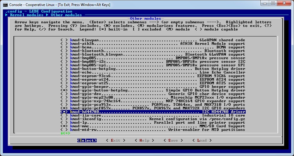
After compiling, updating and reloading, if the autoloading of the module is not enabled, then we try to load, see the result:
root@lede: insmod hd44780 root@lede: lsmod |grep 44780 hd44780 5450 0 We try to add a device:
root@lede: echo hd44780 0x27 > /sys/bus/i2c/devices/i2c-0/new_device [ 9463.913178] i2c i2c-0: new_device: Instantiated device hd44780 at 0x27 On the indicator, as laid down in the driver, when initialized, the address of the created device is issued: "/ dev / lcd0", with a flashing cursor at the end.
On this device, you can send characters that will be displayed on the indicator:
root@lede: echo -n 123 > /dev/lcd0 You can also control the operating modes via sysfs (/ sys / class / hd44780 / lcd0). This path has the following file names: backlight, cursor_display, geometry, cursor_blink. Through them you can customize the geometry of the screen, control the cursor modes and backlight. For example, to turn off the flashing cursor, just give the command
root@lede: echo -n 0 > /sys/class/hd44780/lcd0/cursor_blink In addition, two VT100 terminal commands are supported, this is clearing the screen and setting the cursor to the starting position. You can submit them as follows:
root@lede: echo -n -e '\x1b'[2J > /dev/lcd0 root@lede: echo -n -e '\x1b'[H > /dev/lcd0 Installation of the necessary modes can also be made when booting the OS. To do this, add the file target / linux / apm821xx / base-files / etc / board.d / 03_lcd to LEDE with the contents:
#!/bin/sh echo hd44780 0x27 > /sys/bus/i2c/devices/i2c-0/new_device echo -n 16x2 > /sys/class/hd44780/lcd0/geometry echo -n 0 > /sys/class/hd44780/lcd0/cursor_display echo -n 0 > /sys/class/hd44780/lcd0/cursor_blink echo -n -e '\x1b'[2JHello! > /dev/lcd0 exit 0 Now the board will greet you every time you boot the system.
10. Adding processing of necessary VT100 commands to HD44780 driver
So, the driver works, but for use in LCD4Linux it must be able to place characters in any position on the screen. According to the list of terminal commands, select the desired one:
Esc [Line; ColumnH - Move cursor to screen location v, h
Find the package / hd44780 / src / hd44780-dev.c file and add detection and execution of a new command. It is necessary to refine the procedure for processing esc-sequences:
Original:
static void hd44780_handle_esc_seq_char(struct hd44780 *lcd, char ch) { int prev_row, prev_col; lcd->esc_seq_buf.buf[lcd->esc_seq_buf.length++] = ch; if (!strcmp(lcd->esc_seq_buf.buf, "[2J")) { prev_row = lcd->pos.row; prev_col = lcd->pos.col; hd44780_clear_display(lcd); hd44780_write_instruction(lcd, HD44780_DDRAM_ADDR | (lcd->geometry->start_addrs[prev_row] + prev_col)); hd44780_leave_esc_seq(lcd); } else if (!strcmp(lcd->esc_seq_buf.buf, "[H")) { hd44780_write_instruction(lcd, HD44780_RETURN_HOME); lcd->pos.row = 0; lcd->pos.col = 0; hd44780_leave_esc_seq(lcd); } else if (lcd->esc_seq_buf.length == ESC_SEQ_BUF_SIZE) { hd44780_flush_esc_seq(lcd); } } Modified version:
static void hd44780_handle_esc_seq_char(struct hd44780 *lcd, char ch) { int prev_row, prev_col; struct hd44780_geometry *geo = lcd->geometry; lcd->esc_seq_buf.buf[lcd->esc_seq_buf.length++] = ch; if (!strcmp(lcd->esc_seq_buf.buf, "[2J")) { prev_row = lcd->pos.row; prev_col = lcd->pos.col; hd44780_clear_display(lcd); hd44780_write_instruction(lcd, HD44780_DDRAM_ADDR | (lcd->geometry->start_addrs[prev_row] + prev_col)); hd44780_leave_esc_seq(lcd); } else if (!strcmp(lcd->esc_seq_buf.buf, "[H")) { hd44780_write_instruction(lcd, HD44780_RETURN_HOME); lcd->pos.row = 0; lcd->pos.col = 0; hd44780_leave_esc_seq(lcd); } else if ((lcd->esc_seq_buf.buf[0]=='[') && (lcd->esc_seq_buf.buf[4]=='H') && // Esc[ Line ; Column H (lcd->esc_seq_buf.buf[2]==';' ) && (lcd->esc_seq_buf.length == 5)) { lcd->pos.row = lcd->esc_seq_buf.buf[1] % geo->rows; lcd->pos.col = lcd->esc_seq_buf.buf[3] % geo->cols; hd44780_write_instruction(lcd, HD44780_DDRAM_ADDR | (geo->start_addrs[lcd->pos.row] + lcd->pos.col)); hd44780_leave_esc_seq(lcd); } else if (lcd->esc_seq_buf.length == ESC_SEQ_BUF_SIZE) { hd44780_flush_esc_seq(lcd); } } And it is necessary to change the length of the buffer for accumulation and analysis of esc-sequences. Find the line in the hd44780.h file:
#define ESC_SEQ_BUF_SIZE 4 And correct the value from 4 to 6. You can compile and check. Only one package from LEDE can be compiled.
root@debian:/apm82181-lede-master# make package/hd44780/compile make[1] package/hd44780/compile make[2] -C package/hd44780 compile If there are no errors, then compile the whole project, update, reboot. Checking:
root@lede:/ echo -n -e '\x1b[1;6H' > /dev/lcd0 The cursor moves to the second line and 7th position (numbering from scratch):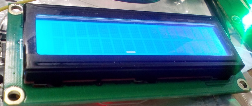
11. Adding a display with some VT100 commands to LCD4Linux
The LCD driver performs its functionality. Now it can be used in the LCD4Linux package to display the system status. However, I did not find a display in it that works with the driver using the terminal protocol.
So we write our own. According to the instructions How to write new display drivers .
Source files can be taken in the build_dir / target-powerpc_464fp_musl-1.1.15 / lcd4linux-custom / lcd4linux-r1203 directory, or from the dl / lcd4linux-r1203.tar.bz2 package.
Just like in the manual:
- From the drv_Sample.c file, drv make a copy of drv_vt100.c
- Edit drv_vt100.c, delete everything related to the graphics mode, with GPIO
- Add new driver to drv.c
- Add to Makefile.am
- Add to drivers.m4
if test "$VT100" = "yes"; then TEXT="yes" I2C="yes" DRIVERS="$DRIVERS drv_vt100.o" AC_DEFINE(WITH_VT100,1,[vt100 driver]) fi - Add to Makefile.am
Next, we write our procedures in the drv_vt100.c file.
drv_vt100_open:
static int drv_vt100_open(const char *section) { char *s; int f = -1; s = cfg_get(section, "Port", NULL); if (s == NULL || *s == '\0' || strlen(s) > 80) { error("%s: no '%s.Port' entry from %s", Name, section, cfg_source()); return -1; } strcpy(Port, s); f = open(Port, O_WRONLY); if (f == -1) { error("open(%s) failed: %s", Port, strerror(errno)); return -1; } close (f); return 0; } drv_vt100_send:
static void drv_vt100_send(const char *data, const unsigned int len) { unsigned int i; int f; f = open(Port, O_WRONLY); write (f, data, len); close (f); } drv_vt100_clear:
static void drv_vt100_clear(void) { char cmd[4]; cmd[0] = 0x1B; // ESC cmd[1] = '['; // [ cmd[2] = '2'; // 2 cmd[3] = 'J'; // J drv_vt100_send(cmd, 4); cmd[2] = 'H'; // H drv_vt100_send(cmd, 3); } drv_vt100_write:
static void drv_vt100_write(const int row, const int col, const char *data, int len) { char cmd[6]; cmd[0] = 0x1B; // ESC cmd[1] = '['; // [ cmd[2] = row & 0xff; // Line cmd[3] = ';'; // ; cmd[4] = col & 0xff; // Column cmd[5] = 'H'; // H drv_vt100_send(cmd, 6); } drv_vt100_close leave empty.
We edit and create files in a separate folder from the LEDE project. Then, since the LCD4linux files are updated from the archive when the project is compiled, changing them in the build_dir / ... folder is pointless. It is necessary to use the opportunity to apply patches. The patches for LCD4Linux are located in the feeds / packages / utils / lcd4linux / patches folder. You need to place your own, adding a new VT100 display driver right there.
To create a patch, we make next two folders. In one (let 1 /) we place original files, in another (let 2 /) the same, but changed. Then run the diff command:
diff -Naur ./1 ./2 > 180-vt100.patch As a result, we have a file 180-vt100.patch with approximately the following content:
diff -Naur ./vt100/Makefile.am ./vt100-f/Makefile.am --- ./vt100/Makefile.am 2016-11-28 11:01:56.000000000 +0000 +++ ./vt100-f/Makefile.am 2016-11-14 07:33:41.000000000 +0000 @@ -125,6 +125,7 @@ drv_USBHUB.c \ drv_USBLCD.c \ drv_vnc.c \ +drv_vt100.c \ drv_WincorNixdorf.c \ drv_X11.c \ \ diff -Naur ./vt100/drivers.m4 ./vt100-f/drivers.m4 --- ./vt100/drivers.m4 2016-11-14 11:54:41.000000000 +0000 +++ ./vt100-f/drivers.m4 2016-11-14 07:37:00.000000000 +0000 @@ -39,7 +39,7 @@ [ Newhaven, Noritake, NULL, Pertelian, PHAnderson,] [ PICGraphic, picoLCD, picoLCDGraphic, PNG, PPM, RouterBoard,] [ Sample, SamsungSPF, serdisplib, ShuttleVFD, SimpleLCD, st2205, T6963,] - [ TeakLCM, TEW673GRU, Trefon, ULA200, USBHUB, USBLCD, VNC, WincorNixdorf, X11], + [ TeakLCM, TEW673GRU, Trefon, ULA200, USBHUB, USBLCD, VNC, vt100, WincorNixdorf, X11], drivers=$withval, drivers=all ) @@ -114,6 +114,7 @@ USBHUB="yes" USBLCD="yes" VNC="yes" + VT100="yes" WINCORNIXDORF="yes" X11="yes" ;; @@ -279,6 +280,9 @@ VNC) VNC=$val ;; + vt100) + VT100=$val + ;; WincorNixdorf) WINCORNIXDORF=$val ;; @@ -869,6 +873,13 @@ fi fi +if test "$VT100" = "yes"; then + TEXT="yes" + I2C="yes" + DRIVERS="$DRIVERS drv_vt100.o" + AC_DEFINE(WITH_VT100,1,[vt100 driver]) +fi + if test "$WINCORNIXDORF" = "yes"; then TEXT="yes" SERIAL="yes" One patch is created for all files. If you look at patches that are already in the feeds / packages / utils / lcd4linux / patches folder, there are no lines inside the files that show the “diff -Naur ...” command being executed. We bring our patch in the same state and copy it to the folder.
Go to the configurator LEDE.
We see the appearance of our display driver in LCD4Linuc-custom: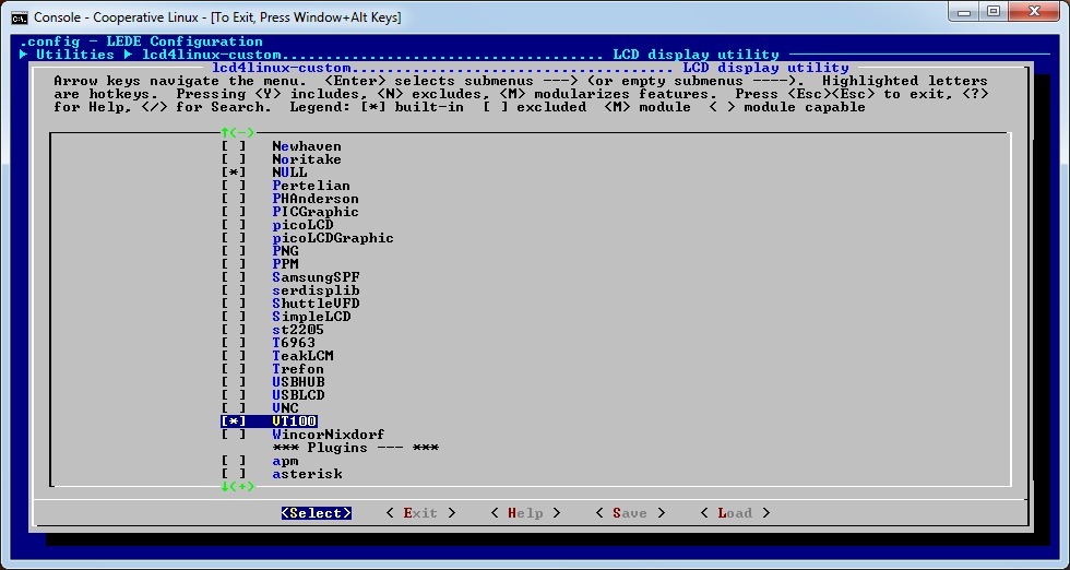
We include it in the project, save the settings, compile, update, reload. We connect our driver in the configuration file:
lcd4linux.conf
Variables { tick 500 tack 100 minute 60000 } Display VT100 { Driver 'vt100' Size '16x2' Port '/dev/lcd0' } Widget Test { class 'Text' expression '1234567890123456' width 16 } Layout Test { Row01.Col1 'Test' Row02.Col1 'Test' } Display 'VT100' Layout 'Test' Checking:
root@lede:/# /usr/bin/lcd4linux -v -F LCD4Linux 0.11.0-SVN-1193 starting vt100: $Rev: 001 $ initializing layout 'Test' Creating new timer group (1000 ms) widget 'Test': Class 'text', Parent '<root>', Layer 1, Row 0, Col 0 (to 0,16) widget 'Test': Class 'text', Parent 'Test', Layer 1, Row 1, Col 0 (to 1,16) On the indicator, we see, as planned in the config, numbers.
12. Adding character generator programming commands to HD44780 and VT100 drivers
The indicator based on the HD44780 controller has a wired Latin alphabet with numbers and signs and freely 8 programmable characters (there are sometimes Russian characters, but not in this case). Changing the display of programmable characters you can get a simple animation. Its variants are presented in the example of the LCD4Linux config, but as long as our drivers do not support this function, we cannot use them.
There is nothing difficult in this, it’s necessary to take 8 bytes in one driver and send it to the character generator with the command, send them in the other.
Fix again
hd44780_handle_esc_seq_char procedure in hd44780-dev.c
static void hd44780_handle_esc_seq_char(struct hd44780 *lcd, char ch) { int prev_row, prev_col; struct hd44780_geometry *geo = lcd->geometry; if (lcd->is_in_set_char == 0) { lcd->esc_seq_buf.buf[lcd->esc_seq_buf.length++] = ch; if (!strcmp(lcd->esc_seq_buf.buf, "[2J")) { prev_row = lcd->pos.row; prev_col = lcd->pos.col; hd44780_clear_display(lcd); hd44780_write_instruction(lcd, HD44780_DDRAM_ADDR | (lcd->geometry->start_addrs[prev_row] + prev_col)); hd44780_leave_esc_seq(lcd); } else if (!strcmp(lcd->esc_seq_buf.buf, "[H")) { hd44780_write_instruction(lcd, HD44780_RETURN_HOME); lcd->pos.row = 0; lcd->pos.col = 0; hd44780_leave_esc_seq(lcd); } else if ((lcd->esc_seq_buf.buf[0]=='[') && (lcd->esc_seq_buf.buf[4]=='H') && // Esc[ Line ; Column H (lcd->esc_seq_buf.buf[2]==';' ) && (lcd->esc_seq_buf.length == 5)) { lcd->pos.row = lcd->esc_seq_buf.buf[1] % geo->rows; lcd->pos.col = lcd->esc_seq_buf.buf[3] % geo->cols; hd44780_write_instruction(lcd, HD44780_DDRAM_ADDR | (geo->start_addrs[lcd->pos.row] + lcd->pos.col)); hd44780_leave_esc_seq(lcd); } else if (!strcmp(lcd->esc_seq_buf.buf, "(S")) { // Esc(S code matrix(8) lcd->is_in_set_char = 1; } else if (lcd->esc_seq_buf.length == ESC_SEQ_BUF_SIZE) { hd44780_flush_esc_seq(lcd); } } else if (lcd->is_in_set_char == 1) { // start set CGRAM code hd44780_write_instruction(lcd, HD44780_CGRAM_ADDR | 8 * (ch & 0x07)); lcd->is_in_set_char++; } else { hd44780_write_data(lcd, ch & 0x1f); // set 8 bytes CGRAM code lcd->is_in_set_char++; if (lcd->is_in_set_char == 10){ // go to DDRAM mode hd44780_write_instruction(lcd, HD44780_DDRAM_ADDR | (geo->start_addrs[lcd->pos.row] + lcd->pos.col)); hd44780_leave_esc_seq(lcd); } } } Add to it the mode of receiving 8 bytes of the character generator and writing them to CGRAM (character generator). Since in VT100 I did not find the ESC-sequence of character programming, I had to think of something. Let it be Esc (S 8 bytes, that is, the ESC code, then the opening parenthesis, the Latin letter S and 8 bytes of the matrix. In our case, if the familiarity size is 8 * 5, only 5 low bits of each byte will be used.
In the hd44780_write procedure, add a reset to the character generator reception mode (line lcd-> is_in_set_char = 0).
hd44780_write
void hd44780_write(struct hd44780 *lcd, const char *buf, size_t count) ... case '\e': lcd->is_in_esc_seq = true; lcd->is_in_set_char = 0; break; default: hd44780_write_char(lcd, ch); ... And we describe this structure field (is_in_set_char) in the header file hd44780.h.
struct hd44780
struct hd44780 { struct cdev cdev; struct device *device; struct i2c_client *i2c_client; struct hd44780_geometry *geometry; struct { int row; int col; } pos; char buf[BUF_SIZE]; struct { char buf[ESC_SEQ_BUF_SIZE]; int length; } esc_seq_buf; bool is_in_esc_seq; int is_in_set_char; bool backlight; bool cursor_blink; bool cursor_display; bool dirty; struct mutex lock; struct list_head list; }; Now add this functionality to the LCD4Linux display driver. The drv_vt100_defchar function of the drv_vt100.c file:
drv_vt100_defchar
static void drv_vt100_defchar(const int ascii, const unsigned char *matrix) { char cmd[12]; int i; /* call the 'define character' function */ cmd[0] = 0x1B; // ESC cmd[1] = '('; // ( cmd[2] = 'S'; // S cmd[3] = ascii & 0x07; // code /* send bitmap to the display */ for (i = 0; i < 8; i++) { cmd[i + 4] = (*matrix++) & 0x1f; } drv_vt100_send(cmd, 12); } Compile, update, reboot. We change again the LCD4linux config.
lcd4linux.conf
Variables { tick 500 tack 100 minute 60000 } Display VT100 { Driver 'vt100' Size '16x2' Port '/dev/lcd0' Icons 1 } Widget RAM { class 'Text' expression meminfo('MemFree')/1024 postfix ' MB RAM' width 11 precision 0 align 'R' update tick } Widget Busy { class 'Text' expression proc_stat::cpu('busy', 500) prefix 'Busy' postfix '%' width 9 precision 1 align 'R' update tick } Widget Uptime { class 'Text' expression uptime('%d days %H:%M:%S') width 20 align 'R' prefix 'Up ' update 1000 } Widget Uptime { class 'Text' expression 'Up '.uptime('%d %H:%M:%S') width 16 align 'L' update 1000 } # Icons Widget Timer { class 'Icon' speed 83 Bitmap { Row1 '.....|.....|.....|.....|.....|.....|.....|.....|.....|.....|.....|.....|.....|.....|.....|.....|.....|.....|.....|.....|.....|.....|.....|.....|' Row2 '.***.|.*+*.|.*++.|.*++.|.*++.|.*++.|.*++.|.*++.|.*++.|.*++.|.*++.|.*++.|.+++.|.+*+.|.+**.|.+**.|.+**.|.+**.|.+**.|.+**.|.+**.|.+**.|.+**.|.+**.|' Row3 '*****|**+**|**++*|**+++|**++.|**++.|**+++|**+++|**+++|**+++|**+++|+++++|+++++|++*++|++**+|++***|++**.|++**.|++***|++***|++***|++***|++***|*****|' Row4 '*****|**+**|**+**|**+**|**+++|**+++|**+++|**+++|**+++|**+++|+++++|+++++|+++++|++*++|++*++|++*++|++***|++***|++***|++***|++***|++***|*****|*****|' Row5 '*****|*****|*****|*****|*****|***++|***++|**+++|*++++|+++++|+++++|+++++|+++++|+++++|+++++|+++++|+++++|+++**|+++**|++***|+****|*****|*****|*****|' Row6 '.***.|.***.|.***.|.***.|.***.|.***.|.**+.|.*++.|.+++.|.+++.|.+++.|.+++.|.+++.|.+++.|.+++.|.+++.|.+++.|.+++.|.++*.|.+**.|.***.|.***.|.***.|.***.|' Row7 '.....|.....|.....|.....|.....|.....|.....|.....|.....|.....|.....|.....|.....|.....|.....|.....|.....|.....|.....|.....|.....|.....|.....|.....|' Row8 '.....|.....|.....|.....|.....|.....|.....|.....|.....|.....|.....|.....|.....|.....|.....|.....|.....|.....|.....|.....|.....|.....|.....|.....|' } } Layout L16x2 { Row1 { Col1 'Uptime' col16 'Timer' } Row2 { Col1 'Busy' Col11 'RAM' } } Display 'VT100' Layout 'L16x2' Checking:
root@lede: /usr/bin/lcd4linux -v -F LCD4Linux 0.11.0-SVN-1193 starting vt100: $Rev: 001 $ vt100: reserving 1 of 8 user-defined characters for icons initializing layout 'L16x2' Creating new timer group (1000 ms) widget 'Uptime': Class 'text', Parent '<root>', Layer 1, Row 0, Col 0 (to 0,16) Creating new timer group (83 ms) widget 'Timer': Class 'icon', Parent '<root>', Layer 1, Row 0, Col 15 (to 1,16) Creating new timer group (500 ms) widget 'Busy': Class 'text', Parent '<root>', Layer 1, Row 1, Col 0 (to 1,9) widget 'RAM': Class 'text', Parent '<root>', Layer 1, Row 1, Col 10 (to 1,21) On the screen, we see the time of the board's work from the last boot, system boot, free memory, and the animation symbol in the form of a filling and clearing disk.
By adding the LCD4Linux config fix to the patch 180-vt100.patch, we will get the same kind of indicator right at boot:
180-vt100.patch
--- a/lcd4linux.conf.sample 2016-11-15 09:47:46.000000000 +0000 +++ af/lcd4linux.conf.sample 2016-11-18 03:18:22.000000000 +0000 @@ -567,7 +567,14 @@ HttpPort '5800' } - +Display VT100 { + Driver 'vt100' + Size '16x2' + Port '/dev/lcd0' + Icons 1 +} + + Display FutabaVFD { Driver 'FutabaVFD' Port '/dev/parport0' @@ -674,7 +681,7 @@ Widget RAM { class 'Text' - expression meminfo('MemTotal')/1024 + expression meminfo('MemFree')/1024 postfix ' MB RAM' width 11 precision 0 @@ -828,6 +835,14 @@ update 1000 } +Widget Uptime { + class 'Text' + expression 'Up '.uptime('%d %H:%M:%S') + width 16 + align 'L' + update 1000 +} + Widget mpris_TrackPosition_bar { class 'Bar' expression mpris_dbus::method_PositionGet('org.kde.amarok') @@ -1015,7 +1030,7 @@ Widget Timer { class 'Icon' - speed 50 + speed 83 Bitmap { Row1 '.....|.....|.....|.....|.....|.....|.....|.....|.....|.....|.....|.....|.....|.....|.....|.....|.....|.....|.....|.....|.....|.....|.....|.....|' Row2 '.***.|.*+*.|.*++.|.*++.|.*++.|.*++.|.*++.|.*++.|.*++.|.*++.|.*++.|.*++.|.+++.|.+*+.|.+**.|.+**.|.+**.|.+**.|.+**.|.+**.|.+**.|.+**.|.+**.|.+**.|' @@ -1225,6 +1240,17 @@ } } +Layout L16x2-2 { + Row1 { + Col1 'Uptime' + col16 'Timer' + } + Row2 { + Col1 'Busy' + Col11 'RAM' + } +} + Layout L20x2 { Row1 { Col1 'CPUinfo' @@ -1323,7 +1349,7 @@ -Display 'ACool' +#Display 'ACool' #Display 'SerDispLib' #Display 'LCD-Linux' #Display 'LCD2041' @@ -1354,7 +1380,7 @@ #Display 'IRLCD' #Display 'USBLCD' #Display 'BWCT' -#Display 'Image' +Display 'Image' #Display 'TeakLCD' #Display 'Trefon' #Display 'LCD2USB' @@ -1363,15 +1389,17 @@ #Display 'ctinclud' #Display 'picoLCD' #Display 'VNC' +Display 'VT100' #Display 'FutabaVFD' #Display 'GLCD2USB' -#Layout 'Default' -Layout 'TestLayer' +Layout 'Default' +#Layout 'TestLayer' #Layout 'TestImage' #Layout 'L8x2' #Layout 'L16x1' #Layout 'L16x2' +Layout 'L16x2-2' #Layout 'L20x2' #Layout 'L40x2' #Layout 'Test' 13. Optimization of data transmission on the I2C bus
Now that everything is working as planned, a little bit about the data transfer rate. I want to draw attention to two points.
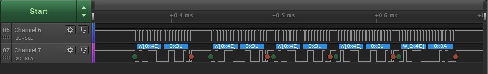
First, the data on the I2C bus is transmitted by very small blocks, and specifically one byte. And each block is added the address of the slave. It is logical to assume that the transfer of the device address with a larger unit will increase the utilization of the bus and reduce the transfer time.
This is how the transmission looks like individual bytes.
— (0x4E).
— (0x4E).
We will carry out partial optimization. To do this, we recall how one byte of data is transmitted to the indicator. LCD works in 4-bit mode, i.e. gets a half a byte at a time. These half-bytes should be confirmed by issuing an “Enable” signal. As a result, to transfer one byte from the processor to the indicator via the I2C bus, there are 6 bytes:
- Older half-byte without “Enable” signal
- Senior half bytes with the “Enable” signal
- Older half-byte without “Enable” signal
- Junior half a byte without the “Enable” signal
- Junior half a byte with the signal "Enable"
- Junior half a byte without the “Enable” signal
And since each is accompanied by an address, this is actually 12 bytes, with a bus speed of 100 KHz, this is 1.2 ms.
It is proposed to transmit the same 6 bytes, but in one block, with one address byte, i.e. 7 bytes instead of 12. Original data transfer procedures from the HD44780 driver.
hd44780_write_data, hd44780_write_nibble, pcf8574_raw_write from hd44780-dev.c
static void pcf8574_raw_write(struct hd44780 *lcd, u8 data) { i2c_smbus_write_byte(lcd->i2c_client, data); } static void hd44780_write_nibble(struct hd44780 *lcd, dest_reg reg, u8 data) { data = (data << 4) & 0xF0; if (reg == DR) data |= RS; data = data | (RW & 0x00); if (lcd->backlight) data |= BL; pcf8574_raw_write(lcd, data); pcf8574_raw_write(lcd, data | E); pcf8574_raw_write(lcd, data); } static void hd44780_write_data(struct hd44780 *lcd, u8 data) { u8 h = (data >> 4) & 0x0F; u8 l = data & 0x0F; hd44780_write_nibble(lcd, DR, h); hd44780_write_nibble(lcd, DR, l); udelay(37 + 4); } The procedure of the driver HD44780, corrected for packet data.
hd44780_write_data from hd44780-dev.c
static void hd44780_write_data(struct hd44780 *lcd, u8 data) { u8 h = (data >> 4) & 0x0F; u8 l = data & 0x0F; u8 buf[5]; h = (h << 4) & 0xF0; l = (l << 4) & 0xF0; h |= RS; l |= RS; h = h | (RW & 0x00); l = l | (RW & 0x00); if (lcd->backlight){ h |= BL; l |= BL; } buf[0] = h | E; buf[1] = h; buf[2] = l; buf[3] = l | E; buf[4] = l; i2c_smbus_write_i2c_block_data(lcd->i2c_client, h, 5, (const u8 *)(&buf[0])); udelay(37 + 4); } Here is the transfer byte 0x1F
And takes 0.67 ms.
Secondly, the default bus speed is 100 KHz, which is not the maximum. Of course, this is the speed recommended for the port extender on the LCD. But at the same time, many developers are talking about uninterrupted operation at 400 KHz. Of course, the use of non-standard mode is justified, if necessary, and thorough testing for the absence of failures, and I can only say how to do it and what happens.
Information on the Internet about the inclusion of the mode could not be found, it was necessary to revise the source code LEDE. As a result, there are two options for enabling fast mode, i.e. 400 kHz.
The first is to pass a parameter to the kernel module. The module is i2c-ibm_iic. The parameter is iic_force_fast. As a result, it is necessary to add i2c-ibm_iic.iic_force_fast = 1 to the kernel parameters at startup. This can be done in the U-boot bootloader for example:
setenv addmisc 'setenv bootargs ${bootargs} i2c-ibm_iic.iic_force_fast=1' After booting the system we have:
root@lede: dmesg | grep i2c [ 0.000000] Kernel command line: root=/dev_nfs rw nfsroot=192.168.1.10:/nfs/debian_ppc/rootfs ip=dhcp console=ttyS0,115200 i2c-ibm_iic.iic_force_fast=1 [ 4.770923] i2c /dev entries driver [ 4.774742] ibm-iic 4ef600700.i2c: using fast (400 kHz) mode [ 10.456041] i2c i2c-0: new_device: Instantiated device hd44780 at 0x27 The second is to specify the bus mode in the device tree (apollo3g.dtsi, fast-mode parameter):
IIC0: i2c@ef600700 { compatible = "ibm,iic"; reg = <0xef600700 0x00000014>; interrupt-parent = <&UIC0>; interrupts = <0x2 0x4>; fast-mode; #address-cells = <1>; #size-cells = <0>; }; After compiling, do not forget to update the device tree on the TFTP server. And the result:
root@lede: dmesg | grep i2c [ 4.774585] i2c /dev entries driver [ 4.778396] ibm-iic 4ef600700.i2c: using fast (400 kHz) mode [ 10.464396] i2c i2c-0: new_device: Instantiated device hd44780 at 0x27 root@lede: ls -al /proc/device-tree/plb/opb/i2c@ef600700 -r--r--r-- 1 root root 4 Nov 18 04:13 #address-cells -r--r--r-- 1 root root 4 Nov 18 04:13 #size-cells drwxr-xr-x 2 root root 0 Nov 18 04:13 . drwxr-xr-x 12 root root 0 Nov 18 04:13 .. -r--r--r-- 1 root root 8 Nov 18 04:13 compatible -r--r--r-- 1 root root 0 Nov 18 04:13 fast-mode -r--r--r-- 1 root root 4 Nov 18 04:13 interrupt-parent -r--r--r-- 1 root root 8 Nov 18 04:13 interrupts -r--r--r-- 1 root root 4 Nov 18 04:13 name -r--r--r-- 1 root root 8 Nov 18 04:13 reg And the transfer rate of byte is 0.19 ms:
Which is almost an order of magnitude better than the original.
As a conclusion, we can say that as a result of the work done, we were able to use the board with a poorly documented processor in open sources in projects where we use Linux (LEDE). The main Ethernet interface, storage on SATA, management through I2C and several ports provide ample opportunities for developers.
And finally, to duplicate the above, the files from LEDE, according to the directory structure (like everything remembered) are available here .
Source: https://habr.com/ru/post/316100/
All Articles