We make a motor control loop with a current reference
Formulation of the problem
This is the second, final article. I remind the purpose: there is a DC motor. The task is to develop, assemble and test a device that allows realizing a control loop with a current reference for this motor. The desired transition time on a locked engine (without back-EMF) is no more than 10 ms.
The text is divided into two articles:
- 1. Measurement of motor resistance and inductance
- 2. Development of the control circuit
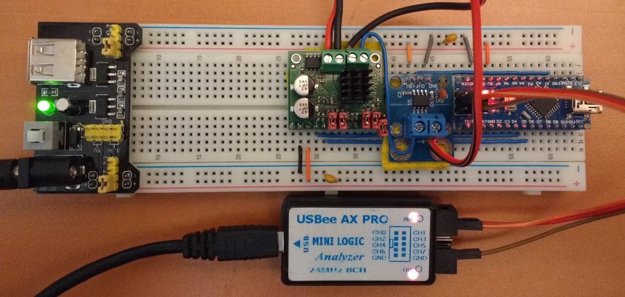
I remind you what the layout of the control iron looks like:
')
Desired result
The whole system is like a black box
So, the whole idea is that I want to directly set the strength of the current flowing through my motor. If you combine the controller and the engine together, then I would like to get something like this:

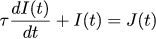
Here J (t) is the current reference, I (t) is the current flowing through the motor. I would like the input and output signals to be connected according to the law τ I '(t) + I (t) = J (t) . This law is chosen arbitrarily, I just like this differential equation. With clever words, it is called an aperiodic link of the first order. Controllers that obey such a law even have their own character on some circuits:

Here is the response of a similar link to a single step effect:

This is a beautiful exponential convergence without various fluctuations, so this form was chosen. The tau constant in the formula τ I '(t) + I (t) = J (t) is called the time constant, this is the time in which the process will reach 63% of its final value in response to a single jump. If we determine the time of the transition process as the time to reach 98% of the final value, then this is approximately 5 tau. In the formulation of the problem, our transition time should not exceed 10 ms, so we take τ = 0.002 .
Let's open the black box
If the black box is opened slightly, then it will look something like this:
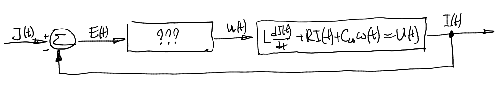
At the input of the black box, we give the signal J (t), the output is the flowing current I (t). Inside the black box there are two bridges: a motor with its diffur connecting the voltage at the terminals U (t) with the current I (t) flowing through it, and the regulator itself, which must supply voltage U (t) depending on the current reference J (t) and really flowing current I (t).
Let's say that the regulator takes the error E (t) as input - this is the difference between the desired amperage and the real one, and the voltage U (t) gives the output. Our task is to find the diffur that binds E (t) and U (t), then it will be clear how to program the arduin of the controller.
So, we want the current task and the real current to be connected according to the law we have chosen:
Apply the Laplace transform to it (with zero initial values):

And make the following proportion:
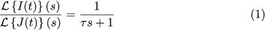
Just in case, in control theory, this proportion is called the transfer function.
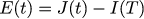
We define the error E (t) as the difference between the desired and the real current:
To adjust the current loop, we fix the motor shaft, so the angular velocity leaves the motor diffura:

In the previous article, we derived the connection between the voltage at the motor terminals and the power of the flowing current (with the rotor fixed):
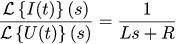
Let's divide this proportion into the proportion from equation (1):

Almost finished, it remains to go from the coordinates of Laplace to the usual temporary. First, let's open the proportion:
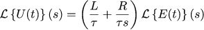
Armed with the Laplace transform tables , you can see the following:
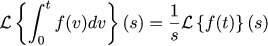
This means that the voltage U (t) and the error of the task E (t) must be connected according to the following law:
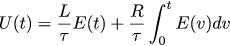
Thus, choosing the behavior of the whole system as an aperiodic link of the first order, we get that the necessary controller is nothing more than a regular PI controller.
Life time
Controller code can be found here. The program is quite standard, the only thing that should be noted is that the atmega does not have enough health to work with floating points. Therefore, all work is carried out with a fixed point and integer variables.
Checking the operation of the regulator
To check the operation of the regulator, let us input a square wave and a sinusoidal signal to its input.
Meander
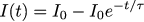
Here you can take the experimental data: from the zero initial state, we set the desired current strength in I0 = 4A and measure the actual flowing current.
Then let's calculate on paper, according to what law the current flow should change in such conditions. This one-to-one coincides with what we did in the previous article:
Let us try to find the value of the parameter so that the theoretical curve best approximates the real data and compares with the time constant we chose earlier. The parameter selection code can be found here.
Here is the result of the operation of the control circuit on the half-period of the meander:
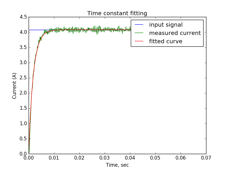
The least squares method tells us that the best value for a parameter is .00184, which is very close to the time constant we chose .002. It is clearly seen that the transition process was within ten milliseconds, which were assigned to it in the formulation of the problem.
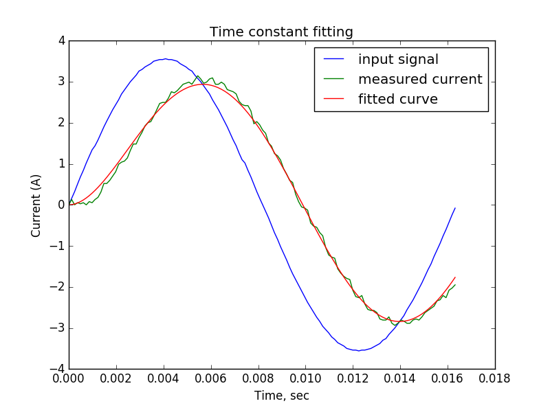
Sine wave signal
Just in case, the second check, again, the calculations are all taken from the previous article. In the case of a sinusoidal setting, the current strength I (t) should change according to the following law:
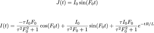
The code for selecting a theoretical curve parameter can be found here. He tells us that the time constant is .00196, which again is close to the calculated parameter of 2ms.
Here is the result of the operation of the control circuit on a sinusoidal input signal:
Conclusion
In general, the devil is not so terrible as he is painted. Many thanks arastas for science! I will try in the foreseeable future to find a little time to collect the inverted pendulum not in the way it did (controlling the voltage), but by controlling the current itself, this should simplify the calculations of the regulator of the pendulum itself.
Source: https://habr.com/ru/post/315488/
All Articles