learnopengl. Lesson 1.6 - Textures
 In the last lesson, we learned to paint our objects in different colors. But in order to achieve some realism, we need a lot of colors. Last time, we painted the vertices of the triangle, if we go the same way, then we will need too many vertices to display the picture. Interested, please under the cat.
Part 1. Start
- Opengl
- Creating a window
- Hello window
- Hello triangle
- Shaders
- Textures
- Transformations
- Coordinate systems
- Camera
Part 2. Basic lighting
Part 3. Loading 3D Models
')
Part 4. OpenGL advanced features
- Depth test
- Stencil test
- Mixing colors
- Face clipping
- Frame buffer
- Cubic cards
- Advanced data handling
- Advanced GLSL
- Geometric shader
- Instancing
- Smoothing
Part 5. Advanced Lighting
Programmers and artists prefer to use textures . The texture is a 2D image (1D and 3D texture also exist) used to add details to the object; Consider that the texture is a piece of paper with a picture of a brick (for example) that is glued to your house and it seems that your house is made of brick.
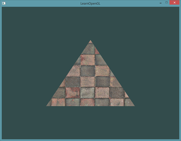
In addition to images, textures can store large data sets sent to shaders, but we will leave this question for another lesson. Below you can see the texture of a brick wall stuck on a triangle from the last lesson.
In order to bind a texture to a triangle, we must tell each vertex of the triangle which part of the texture this vertex belongs to. Each vertex must have texture coordinates associated with a part of the texture.
Texture coordinates are between 0 and 1 along the x and y axis (we use 2D textures). Getting texture color using texture coordinates is called sampling. Texture coordinates start at (0, 0) in the lower left corner of the texture and end with (1, 1) in the upper right corner. The image below shows how we superimposed the texture coordinates on the triangle:
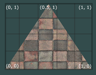
We specified 3 texture coordinates for the triangle. We want the lower left corner of the triangle to correspond with the lower left corner of the texture, so we pass (0, 0) to the lower left vertex of the triangle. Accordingly, we transfer (1, 0) to the bottom right vertex. The upper vertex of the triangle should correspond to the central part of the upper side of the texture, so we transfer to the upper vertex (0.5, 1.0) as the texture coordinate.
As a result, the texture coordinates for the triangle should look something like this:
GLfloat texCoords[] = { 0.0f, 0.0f, // 1.0f, 0.0f, // 0.5f, 1.0f // }; Texture sampling can be performed by various methods. Our job is to tell OpenGL how it should do the sampling.
Texture wrapping
Texture coordinates are often between (0,0) and (1,1) , but what happens if texture coordinates fall outside this range? The default behavior of OpenGL is to repeat the image (in fact, the integer part of the floating-point number is simply ignored), but there are also other options:
- GL_REPEAT : Standard behavior for textures. Replaces the texture.
- GL_MIRRORED_REPEAT : It looks like _GL REPEAT , except that the image is reflected in this mode.
- GL_CLAMP_TP_EDGE : Binds coordinates between 0 and 1 . As a result, coordinates outside the boundaries will be bound to the texture border.
- GL_CLAMP_TO_BORDER : Coordinates outside the range will give the user-defined border color.
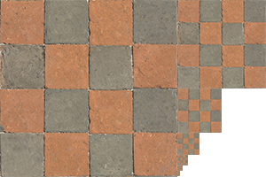
Each of these options is displayed differently when using texture coordinates that extend beyond the gap. The image below perfectly demonstrates the differences:

Each of the above options can be set on the axis ( s , t (and r if you use 3D textures), equivalent to x , y and z ) using the ** glTextParameter *** functions:
glTexParameteri(GL_TEXTURE_2D, GL_TEXTURE_WRAP_S, GL_MIRRORED_REPEAT); glTexParameteri(GL_TEXTURE_2D, GL_TEXTURE_WRAP_T, GL_MIRRORED_REPEAT); The first argument defines the goal to which our texture is attached, we work with a 2D texture, so our value will be GL_TEXTURE_2D . The second value is required to tell OpenGL which particular parameter we want to set. We want to configure the WRAP option and specify its value for the S and T axes. The last argument passed the selected wrapping method. In this case, we use GL_MIRRORED_REPEAT .
If we had chosen GL_CLAMP_TO_BORDER , then we would still have to specify the color of the borders. This is done fv alternative glTextParameter with the transfer to it GL_TEXTURE_BORDER_COLOR as an option and an array of floating-point numbers as a color value.
float borderColor[] = { 1.0f, 1.0f, 0.0f, 1.0f }; glTexParameterfv(GL_TEXTURE_2D, GL_TEXTURE_BORDER_COLOR, borderColor); Texture filtering
Texture coordinates are not dependent on resolution, but they can take any floating point values, so OpenGL needs to understand which pixel of the texture (also called Texel ) it needs to impose. This problem becomes most acute if you want to impose a low-resolution texture on a large object. You may have already guessed that in OpenGL there is an option for filtering textures. There are several options available, but we will discuss only the most important ones: GL_NEAREST and GL_LINEAR .
GL_NEAREST (also called the nearest neighbor filter ) is the standard OpenGL filtering method. As long as it is installed, OpenGL will select the pixel that is closest to the texture coordinate. Below you can see 4 pixels and a cross showing the texture coordinate. Since the center of the upper left texel is closest to the texture coordinate, it is chosen as the color of the sample.

GL_LINEAR (also called (bi) linear filtering ). Accepts the interpolated value from the texels closest to the texture coordinate. The closer the texel is to the texture coordinate, the greater the color multiplier of this texel.
Below you can see an example of mixing colors of neighboring pixels:

But what is the visual effect of the selected filtering effect? Let's see how these methods will work with the texture in a small resolution on a large object (the texture has been enlarged so that you can see individual texels):

Mipmaps
Imagine that you have a large room with thousands of objects, each of which is attached to the texture. Some of the objects are closer to the observer, some of the objects are farther from the observer and each object has a high resolution texture attached. When the object is far from the observer, only a few fragments need to be processed. OpenGL has difficulty getting the right color for a fragment from a high-resolution texture when you have to take into account a large number of texture pixels. This behavior will generate artifacts on small objects, not to mention excessive memory waste associated with the use of high-resolution textures on small objects.
To solve this problem, OpenGL uses a technology called mipmaps, which provides a set of texture images where each subsequent texture is half the size of the past. The idea behind the mipmap is quite simple: after a certain distance from the observer, OpenGL will use a different mipmap texture that will look better at the current distance. The farther away from the observer the object is, the less texture will be used, since it will be more difficult for the user to notice the difference between texture resolutions. Also, mipmaps have a pleasant property of increasing productivity, which is never superfluous. Let's take a closer look at the mipmap example:
Creating a set of mipmap textures for each image is rather a chore, but fortunately OpenGL can generate them by calling glGenerateMipmaps after creating the texture. Soon we will see an example.
While switching between mipmap levels during the rendering process, OpenGL may display some artifacts, such as sharp edges between two levels. As it is possible to use filtering on textures, it is also possible to use filtering at various mipmap levels using NEAREST and LINEAR filtering to switch between levels. To specify the filtering method between mipmap levels, we can replace the standard methods with one of the following four settings:
- _GL_NEARESET_MIPMAP NEAREST : Selects the closest mipmap associated with the pixel size and also uses the nearest neighbor interpolation for texture sampling.
- _GL_LINEAR_MIPMAP NEAREST : Selects the nearest mipmap and samples it using linear interpolation.
- _GL_NEAREST_MIPMAP LINEAR : Linear interpolation between the two closest mipmaps and texture sampling using linear interpolation.
As with texture filtering, we can set the filtering method using the glTexParameteri function
glTexParameteri(GL_TEXTURE_2D, GL_TEXTURE_MIN_FILTER, GL_LINEAR_MIPMAP_LINEAR); glTexParameteri(GL_TEXTURE_2D, GL_TEXTURE_MAG_FILTER, GL_LINEAR); A common mistake is to set the mipmap filtering method as a magnifying filter. This will have no effect, since mipmaps are mainly used when reducing texture. Enlargement of the texture does not use mipmaps, therefore, when passing the filter option to mipmaps, it generates an error GL_INVALID_ENUM .
Loading and creating textures
Before we start using our textures, we need to load them into our application. Texture images can be stored in a limitless number of formats, each of which has its own structure and data ordering, so how do we transfer our image to the application? One solution is to use a convenient format, for example. PNG and write your own system for loading images into a large array of bytes. Although writing your own image uploader does not constitute a very heavy job, it’s still quite tedious, especially if you want to use many file formats.
Another solution is to use a ready-made library for downloading images, which would support many different popular formats and do a lot of hard work for us. For example SOIL .
SOIL
SOIL stands for Simple OpenGL Image Library, supports most popular image formats, is easy to use and can be downloaded from here . Like most other libraries, you will have to generate the .lib file yourself. You can use one of their projects located in the / projects folder (do not worry if their project version is lower than your VS version. Just convert them to a new version, this should work in most cases) to create your own based on it. Also add the contents of the src folder to your include folder. Also, do not forget to add SOIL.lib to your linker settings and add #include <SOIL.h> at the beginning of your code.
For the current texture section we will use the image of a wooden container . To load an image via SOIL, we use the SOIL_load_image function:
int width, height; unsigned char* image = SOIL_load_image("container.jpg", &width, &height, 0, SOIL_LOAD_RGB); The first argument of the function is the location of the image file. The second and third arguments are pointers to int into which the image dimensions will be placed: width and height. We need them to generate the texture. The fourth argument is the number of image channels, but we will leave there just 0. The last argument tells SOIL how to load the image: we need only RGB image information. The result will be stored in a large array of bytes.
Texture generation
As with any other object in OpenGL, identifiers refer to textures. Let's create one:
GLuint texture; glGenTextures(1, &texture); The glGenTextures function takes as the first argument the number of textures to generate, and the second argument is the GLuint array in which the identifiers of these textures will be stored (in our case, this is one GLuint ). Just like any other object, we will bind it so that functions using textures know which texture to use.
glBindTexture(GL_TEXTURE_2D, texture); After binding the texture, we can start generating texture data using the preloaded image. Textures are generated using glTexImage2D :
glTexImage2D(GL_TEXTURE_2D, 0, GL_RGB, width, height, 0, GL_RGB, GL_UNSIGNED_BYTE, image); glGenerateMipmap(GL_TEXTURE_2D); This function has quite a lot of arguments, so let's take one step at a time:
- The first argument describes the texture target. By setting the value of GL_TEXTURE_2D, we told the function that our texture is tied to this target (so that other targets GL_TEXTURE_1D and GL_TEXTURE_3D will not be involved).
- The second argument describes the mipmap level for which we want to generate a texture, if suddenly we want to generate mipmaps ourselves. Since we will leave the Mipmap generation on OpenGL, we will pass 0.
- The third argument tells OpenGL in which format we want to store the texture. Since our image has only RGB values, we will also store only RGB values in textures.
- The fourth and fifth arguments specify the width and height of the resulting texture. We got these values earlier while loading the image.
- The sixth argument should always be 0. (The argument is obsolete).
- The seventh and eighth arguments describe the format and data type of the original image. We loaded RGB values and stored them in bytes (char) so we pass these values.
- The final argument is the image data itself.
After calling glTexImage2D, the current bound texture will have an image bound to it. True, the texture will have only the base image and if we want to use mipmaps, then we will have to set the image in the same way simply by incrementing the value of the mipmap level. Well, or we can just call glGenerateMipmap after generating the texture. This function will automatically generate all the required mipmaps for the currently bound texture.
After the end of texture generation and mipmaps, it is good practice to free up a section of memory allocated for the loaded image and untie the texture object.
SOIL_free_image_data(image); glBindTexture(GL_TEXTURE_2D, 0); The whole texture generation process looks like this:
GLuint texture; glGenTextures(1, &texture); glBindTexture(GL_TEXTURE_2D, texture); // ( ) ... // int width, height; unsigned char* image = SOIL_load_image("container.jpg", &width, &height, 0, SOIL_LOAD_RGB); glTexImage2D(GL_TEXTURE_2D, 0, GL_RGB, width, height, 0, GL_RGB, GL_UNSIGNED_BYTE, image); glGenerateMipmap(GL_TEXTURE_2D); SOIL_free_image_data(image); glBindTexture(GL_TEXTURE_2D, 0); Texture application
For the next chapters, we'll use the quad drawn with * glDrawElements from the last part of the Hello Triangle lesson. We need to tell OpenGL how to sample the texture, so we will update the vertex data by adding texture coordinates to them:
GLfloat vertices[] = { // // // 0.5f, 0.5f, 0.0f, 1.0f, 0.0f, 0.0f, 1.0f, 1.0f, // 0.5f, -0.5f, 0.0f, 0.0f, 1.0f, 0.0f, 1.0f, 0.0f, // -0.5f, -0.5f, 0.0f, 0.0f, 0.0f, 1.0f, 0.0f, 0.0f, // -0.5f, 0.5f, 0.0f, 1.0f, 1.0f, 0.0f, 0.0f, 1.0f // }; After adding additional attributes, we will again have to notify OpenGL about our new format: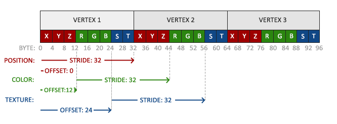 .
.
glVertexAttribPointer(2, 2, GL_FLOAT,GL_FALSE, 8 * sizeof(GLfloat), (GLvoid*)(6 * sizeof(GLfloat))); glEnableVertexAttribArray(2); Notice that we also adjusted the step value of the last two attributes under 8 * sizeof (GLfloat) .
Then we need to change the vertex shader so that it accepts the texture coordinates as an attribute and then passes them to the fragment shader:
#version 330 core layout (location = 0) in vec3 position; layout (location = 1) in vec3 color; layout (location = 2) in vec2 texCoord; out vec3 ourColor; out vec2 TexCoord; void main() { gl_Position = vec4(position, 1.0f); ourColor = color; TexCoord = texCoord; } The fragment shader should also accept a TexCoord as an input variable.
The fragment shader should also have access to the texture object, but how do we pass it to the fragment shader? GLSL has a built-in data type for texture objects, called a sampler whose texture type is as an ending, ie sampler1D, sampler3D and, in our case, sampler2D . We can add texture to the fragment shader by simply declaring a uniform smpler2D to which we will later transfer the texture.
#version 330 core in vec3 ourColor; in vec2 TexCoord; out vec4 color; uniform sampler2D ourTexture; void main() { color = texture(ourTexture, TexCoord); } For sampling the color of the texture, we use the texture function built into GLSL, which takes the texture sampler as the first argument and texture coordinates as the second argument. The texture function then samples the color value using the texture parameters we set earlier. The result of this fragment shader is the (filtered) texture color at the (interpolated) texture coordinate.
It remains only to bind the texture before calling glDrawElements and it will automatically be transferred to the fragment shader sampler:
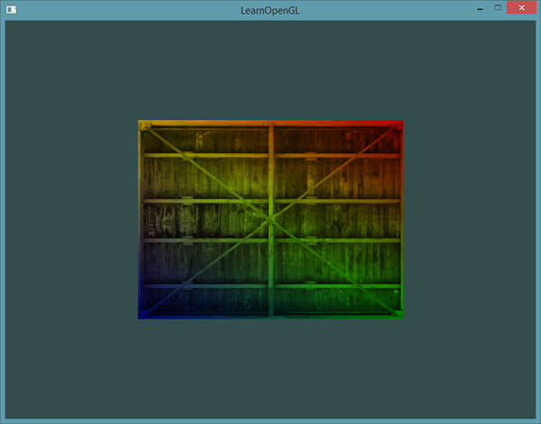
glBindTexture(GL_TEXTURE_2D, texture); glBindVertexArray(VAO); glDrawElements(GL_TRIANGLES, 6, GL_UNSIGNED_INT, 0); glBindVertexArray(0); If you did everything right then you will get the following image:

If your quad is completely black or white, then you are wrong somewhere. Check the shader logs and compare your code with the original one .
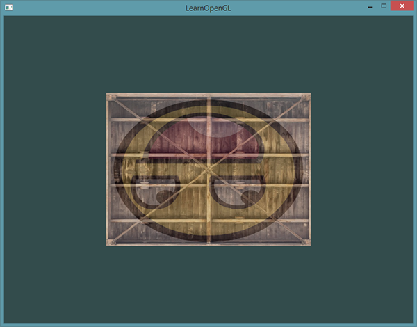
For a more colorful effect, we can mix the resulting color of the texture with the vertex color. For blending, we simply multiply the colors in the fragment shader.
Color = texture(ourTexture, TexCoord) * vec4(ourColor, 1.0f); You should have something like that?
Texture block
Perhaps you are wondering: “Why is the sampler2D variable uniform if we never assigned any value to it using glUniform ?”. With the help of glUniform1i, we can assign the value of the metaposition to the texture sampler so that we can use several textures in one fragment shader. The location of the texture is often called the texture block. The default texture block is 0, which means the current active texture block so that we do not need to specify a location in the previous section.
The main purpose of texture units is to ensure that more than 1 texture can be used in our shader. By passing the texture blocks to the sampler, we can snap several textures at a time as long as we activate the corresponding texture blocks. Like glBindTexture, we can activate textures with glActivateTexture by passing the texture block we want to use there:
glActiveTexture(GL_TEXTURE0); // glBindTexture(GL_TEXTURE_2D, texture); After activating the texture unit, a subsequent call to glBindTexture will bind this texture to the active texture unit. The GL_TEXTURE0 block is always activated by default, so we did not need to activate the texture blocks in the last example.
OpenGL supports at least 16 texture units, which you can get through GL_TEXTURE0 - GL_TEXTURE15 . They are declared in order, so you can also get them as follows: GL_TEXTURE8 = GL_TEXTURE0 + 8 . This is useful if you have to iterate through texture units.
In any case, we still need to change the fragment shader to accept another sampler:
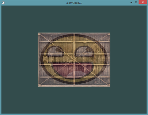
#version 330 core ... uniform sampler2D ourTexture1; uniform sampler2D ourTexture2; void main() { color = mix(texture(ourTexture1, TexCoord), texture(ourTexture2, TexCoord), 0.2); } The final result is a combination of two textures. GLSL has a built-in mix function that takes two values as input and interpolates them based on the third value. If the third value is 0.0, then this function will return the first argument, if 1.0, then the second one. A value of 0.2 will return 80% of the first input color and 20% of the second input color.
Now we need to load and create another texture; You are already familiar with the following steps. Make sure you create another texture object, load the image, and generate the final texture using glTexImage2D . For the second texture, we use the face image while learning these lessons .
In order to use the second texture (and the first one) we will need to slightly modify the drawing procedure, linking both textures to the corresponding texture units and indicating to which sampler which texture unit belongs:
glActiveTexture(GL_TEXTURE0); glBindTexture(GL_TEXTURE_2D, texture1); glUniform1i(glGetUniformLocation(ourShader.Program, "ourTexture1"), 0); glActiveTexture(GL_TEXTURE1); glBindTexture(GL_TEXTURE_2D, texture2); glUniform1i(glGetUniformLocation(ourShader.Program, "ourTexture2"), 1); glBindVertexArray(VAO); glDrawElements(GL_TRIANGLES, 6, GL_UNSIGNED_INT, 0); glBindVertexArray(0); Notice that glUniform1i was used to set the position of the texture unit in a uniform sampler. Installing them through glUniform1i we will be sure that the uniform sampler corresponds with the correct texture unit. As a result, you will need to get the following result:
You probably noticed that the texture is turned upside down! , OpenGL 0.0 Y , 0.0 Y. , Devil Y . SOIL . SOIL SOIL_load_OGL_texture , SOIL_FLAG_INVERT_Y , . , OpenGL, SOIL_load_image .
2 :
- Y ( Y 1)
- Y , TexCoord TexCoord = vec2(texCoord.x, 1.0f — texCoord.y);. .
— , . , , — , , OpenGL.
Y :
Exercises
.
- , , .
- , 0.0f 2.0f 0.0f 1.0f . , 4 . ,
- , . GL_NEAREST , . The decision .
- uniform 3 mix . . ,
Source: https://habr.com/ru/post/315294/
All Articles