MegaFon Laboratory: How a Mobile Operator Tests a Technique
It turns out that MegaFon has a laboratory in St. Petersburg that deals with various interesting things - from testing new handsets even before they are officially released to the market to write requirements for the speed of response of the touch screen. Today we will go through this Lab, get to know its inhabitants and learn many scary words:
Do not understand anything? Nothing, after reading the article will be!
If you are interested - please under the cat!
In general, why does a cellular operator need a laboratory? First of all, such a Laboratory allows reducing maintenance costs without compromising its quality. How is this achieved? In several ways:
')
1) Testing the majority of new mobile technology, before it hits the shelves. According to the results of this testing, firstly, a dialogue begins with the manufacturer, the result of which is fine tuning (as a rule, software) of the radio part of the device to improve its work on the network. Secondly, the decision is made on the admission of devices in their own retail Megafon (all these brand-name stores).

Test world for checking the quality of the phone's cameras, included in the list of 250 tests for any device sold insaloons of Megafon salons
2) Studying the device support for new data transfer functions. The fact is that manufacturers of devices (hardware) and programs (so-called device firmware) sell their solutions to telecom operators in very different configurations: from the cheapest with the minimum of functions to sophisticated, with full support for all possible communication standards.
Thus, a small telecom operator somewhere in Indonesia buys a low-cost solution that will be enough for him for a long time - because most of his subscribers still go with push-button dialers, and a large operator in a million-plus city takes a decision with the support of modern standards, otherwise he cannot keep up with race speeds and ensure their subscribers sane quality of work.
In addition, the constant increase in speed is a vital way in the face of increasing number of devices and increasing traffic. The fact is that the bandwidth is divided into all subscribers who are in range. And the faster the subscriber downloads the file he needs, the faster the channel will free up and increase the speed for other subscribers.
 BS control panel (base station). In the control panel, you can configure the BS with supported protocols and modes
By the way, the same goal is pursued by the first direction of the Laboratory's work - the better the client device is configured, the less it will interfere with neighboring devices, the less it will consume network capacity, and the faster it will transmit data, which means it will improve the quality of communication for all others subscribers
Thus, the Laboratory saves the operator’s money, allowing him, instead of building additional base stations, to improve communication devices and protocols. And saving the operator’s money is reducing the rate of growth of tariffs for its users.
What is a laboratory?
First, it is infrastructure.
For example, three screened rooms for testing, in which you can create any conditions and combinations of existing networks.
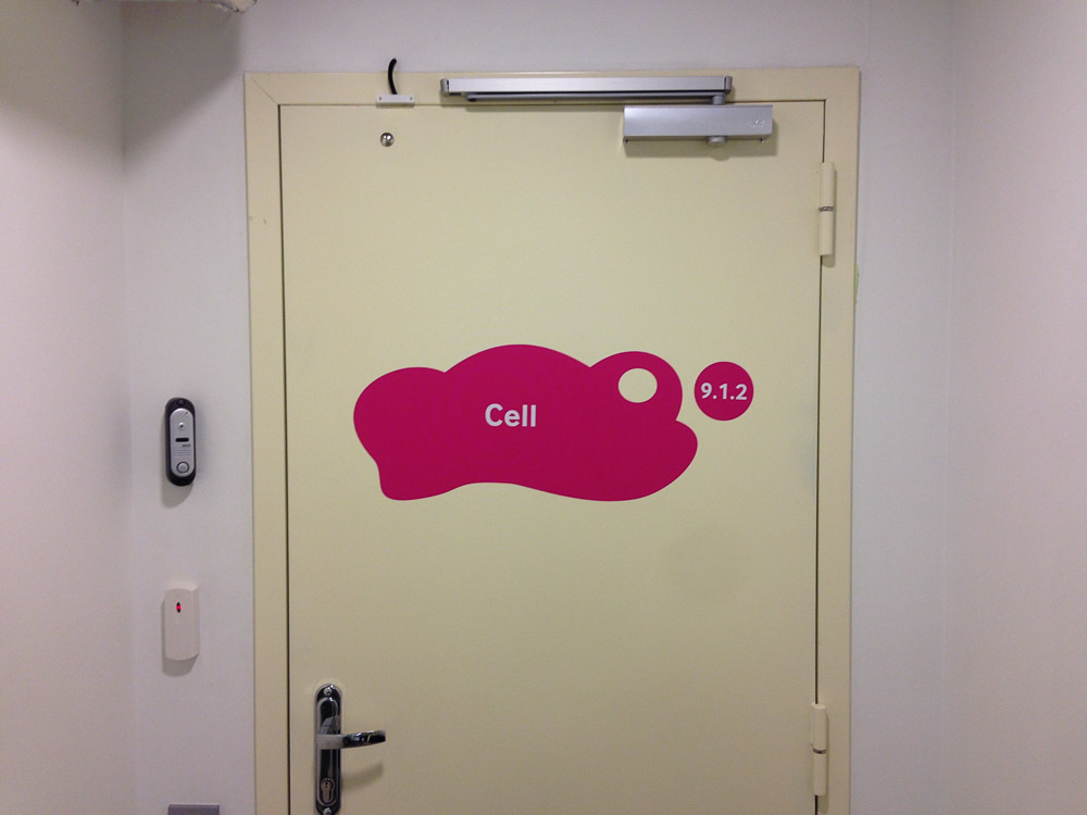 The door to the shielded room. You are the captain yourself.
A lot of shield boxes (these are the same things as rooms, only small ones and are put on the table).

Shield box, placed inside the test device
Several base stations: LTE, 3G, 2G.
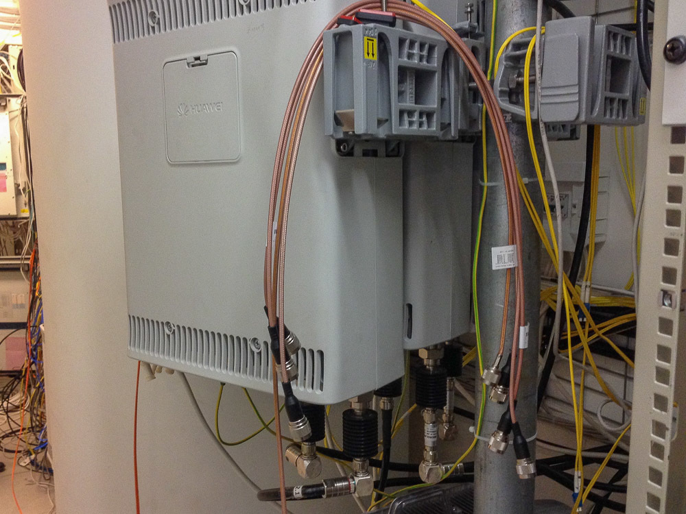
Radio head BS production Huawei
Secondly, this is an understanding of how to test devices.
For example, when surveying subscribers in stores across the country, it turned out that what matters most for the average customer is not the amount of memory, and not the processor speed, and not the quality of the camera. In the half hour that usually passes from entering the store to buying a phone, the most important thing is how smoothly the interface works and how well the sensor perceives pressing.
It’s not clear how to know it, but how to measure it, because the assessment of “well, norms like” cannot be conveyed to the manufacturers.
Therefore, the Laboratory had to develop from scratch a procedure for testing the phone's sensor, which allowed the subjective assessment to be quantified - points. The procedure tests both the surface mark, the absence of dead zones, the speed of response, positioning accuracy, and so on.

A small part of the devices that have been tested
In the future, this procedure will be included in the global document on the Requirements of the Operator for devices, dedicated to testing protocols and test results, which will be available to mobile device vendors - they will be able to carry out tests on their equipment in advance, saving time. The cycle of passing all tests in the Laboratory ranges from two weeks to a month, after each cycle, the manufacturer sends a test document, he corrects the flaws, and sends them back to testing. Usually, such iterations require from 3 to 10, the Lab hopes that the document will reduce this number at least a couple of times.
Third, these are people. In the process of working here, employees acquire a unique experience with a specific hardware, which is very much appreciated - one person has already left to work at Apple, the other two have been hired by equipment manufacturers - Nokia and Huawei, another one is currently working at Qualcomm. The competence of employees allows them to create such protocols and documents for testing, as described above, which ultimately helps the entire mobile communications industry. In addition, cuties work here:
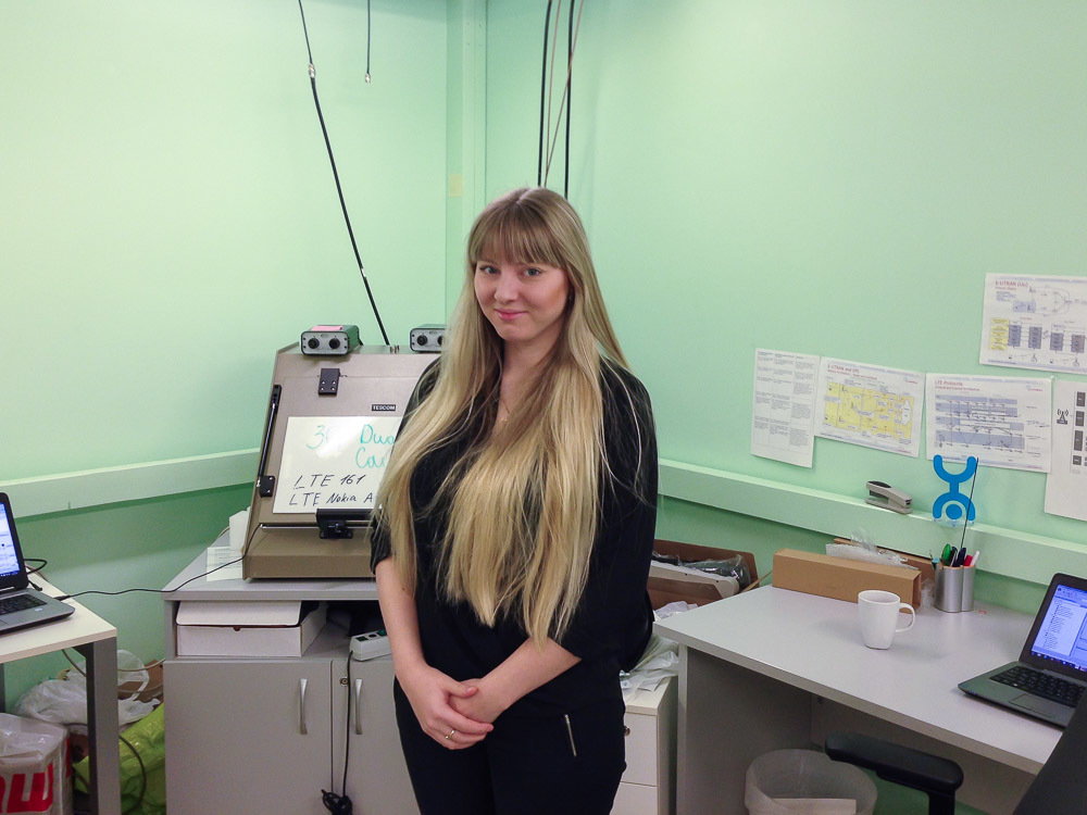
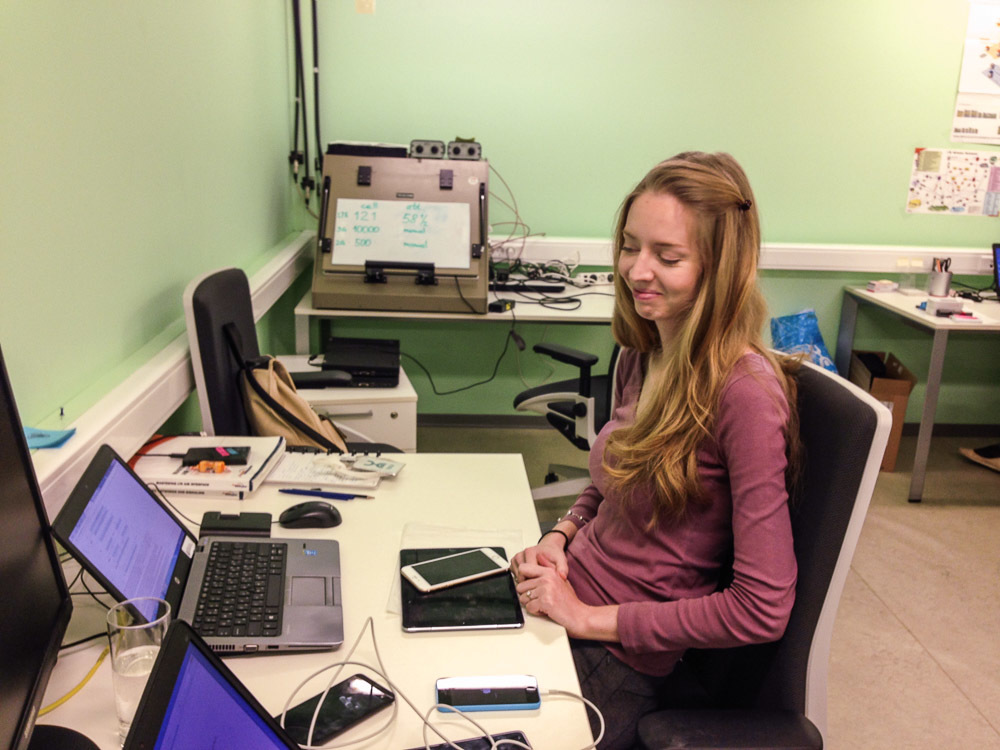
Maria - Subscriber Equipment Testing Engineer
We were led around the Lab and told more about what is in it.
This is one of the screened rooms (there are three of them).

Rooms differ in the color of the walls - this is the "yellow room"
Do not be deceived by the quite usual appearance - under the layer of finishing there is a shielding metal mesh and special plaster that provide almost complete shielding of the interior of the room from any radiation outside. It does not accept the building's WiFi, you cannot talk on the radio, radio receivers do not work, cellular networks are not caught. An ideal place for people who are “ allergic ” to radio-radiation . Only one problem - the construction of such a room will cost about $ 100,000.
In order to be in this room, you can talk on the phone, here is installed femtocell:

The black block is the femto cell. Such a device in the presence of the Internet to create a network operator anywhere. To ensure that they are not taken away to the resorts of Turkey, they are provided with protection and GPS trackers.
However, by itself, the screened room is useless - if there is no connection, then there is nothing to test. In order to create test conditions in it, radio paths from base stations are entered into it:
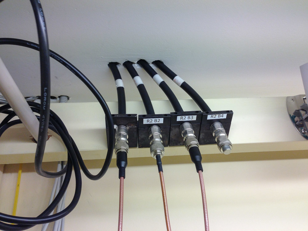
In each room there are 4 inputs that can be switched to any BS and their combinations using the cross panel
These pins are connected to the antennas, creating anintimate atmosphere in the room network of the operator in miniature:

Antennas - Gray Quarter Cylinders
Inside the room, usually the current configuration is written on the blackboard, what and where is connected:

Green lab configuration, inter freq, intra freq, sweets for April ... WHAT?
We ask what happened to the candy for April.
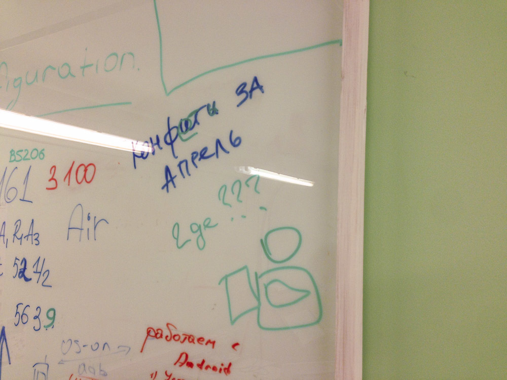
They say they were in March. OK. Let's return to our BSrams .
Conclusions from the BS can be connected not only to the rooms, but also to the shieldboxes:

It is written on the shieldbox to which BS it is connected
Shieldbox - this is the same room, only in miniature. It also has several antenna inputs and the antennas themselves inside:
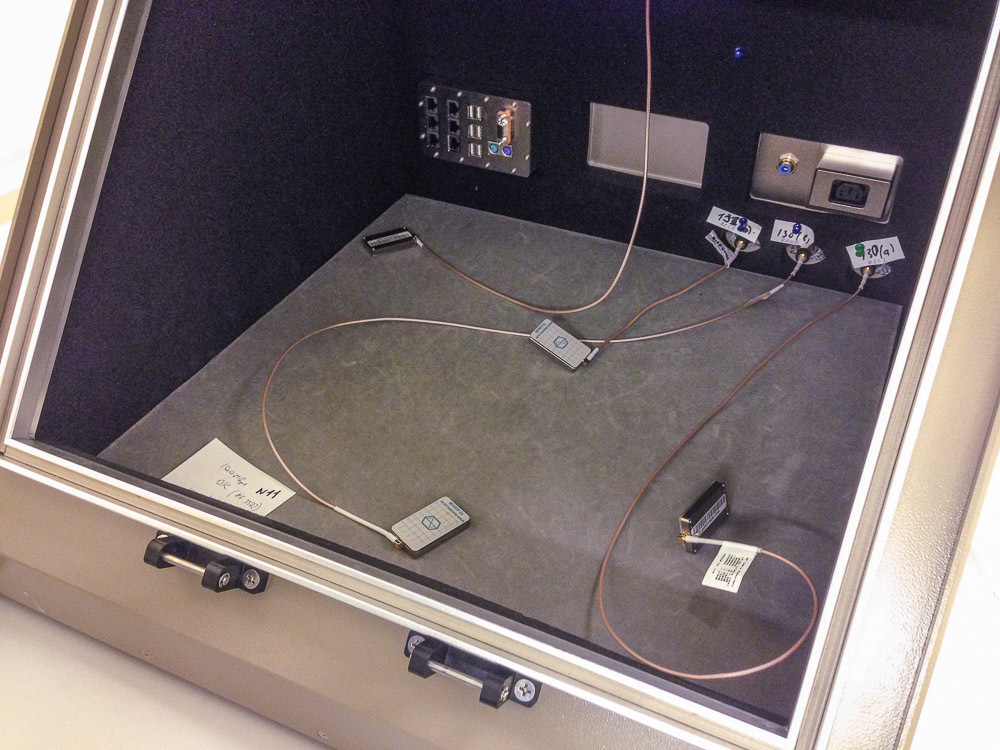
In this box, there are three inputs for antennas, as well as input power, Ethernet, USB, COM-port and PS / 2
The antenna of the shieldbox itself looks like this:

An antenna grid is needed to accurately position it on the device under test, for example, when a radiation pattern is measured.
Some shieldboxes are quite small:

True, they are still expensive
If rooms are used for multiple testing (when a dozen or two devices are hung up on the BS, and they look at how they digest each other), tests on people (talk, hold in hands, test the Internet speed while surfing) Shield boxes are mainly used to test and configure single devices. For example, load testing of Zyxel CPE with LTE-Advanced:
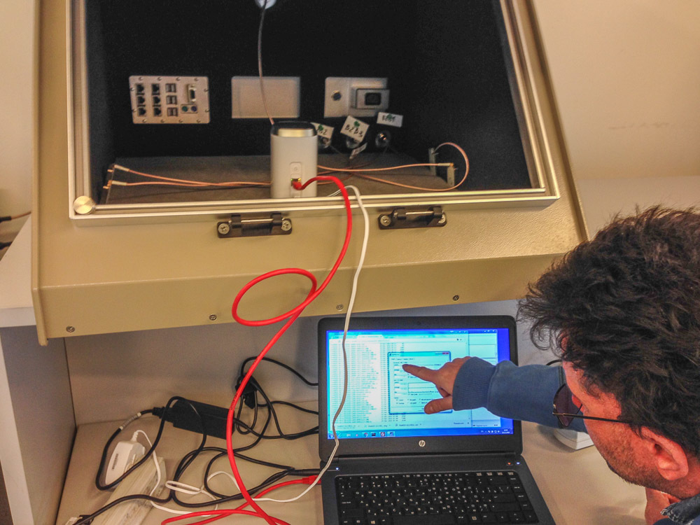
In the photo: Alexander Jakonia (head of the Laboratory), Zyxel (router). Zyxel on the left.
466 Gbit already downloaded:
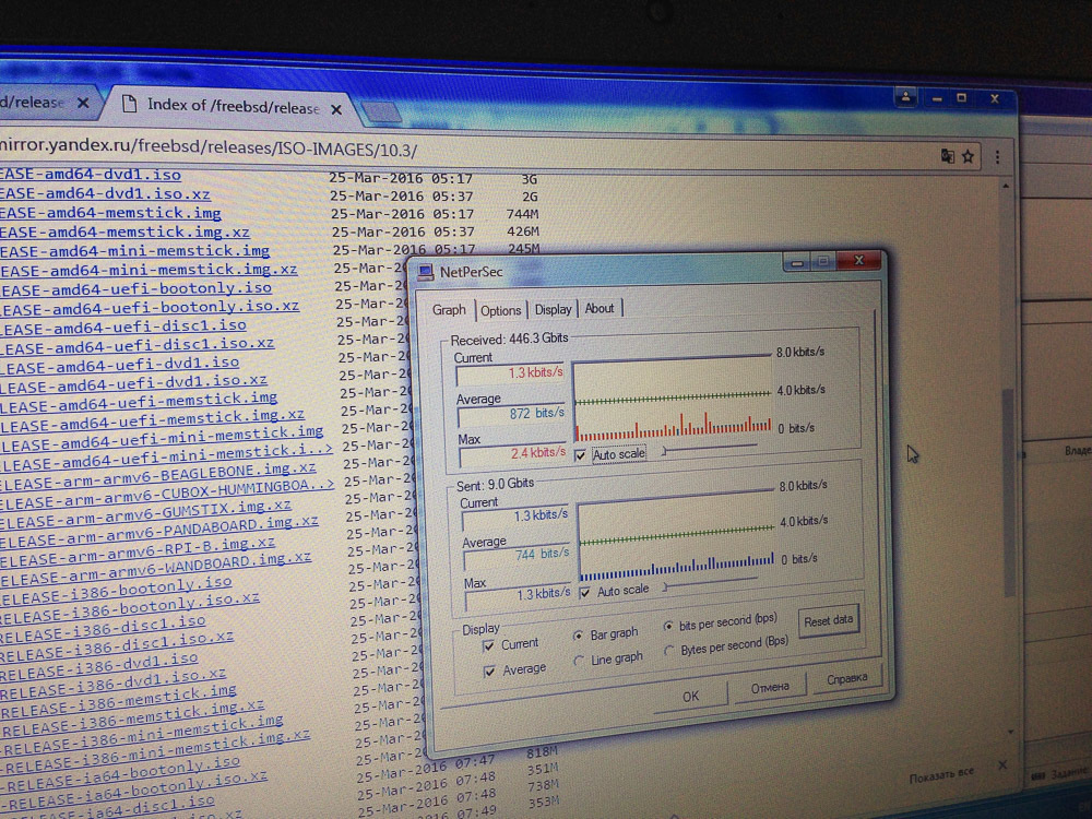
Usually for testing just download some big file.
But debugging by the Chinese manufacturers of their new WiFi-modem looks like:

On the router, placed in the shield box, the test firmware is flooded, and the router itself is connected to the computer on which the Chinese conjure with the parameters through TeamViewer
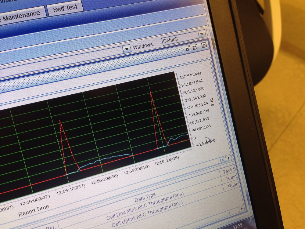
From the shieldbox we return to the screened rooms. Today, the iPhone 7 is being tested there - the first of the iPhone on the Russian market, which supports the aggregation of three carriers. 6S supported only two.
What is it for? To increase speed, of course. All previous devices supported the aggregation of a maximum of two channels of 20 MHz each, which gave a theoretical ceiling with a maximum speed of 300 mbps. In reality, there were less - about 280. The 10 MHz band is about 70 Mbit speed. Two carriers at 20 MHz, plus a third one with a width of 10 MHz, it turns out (70 + 70) * 2 + 70 = 350mbits. Here, for example, it turned out 330mbit:

If the speed is above 300 Mbps, then it is already above the theoretical limit for two carriers
In general, as I said, this speed is needed not so much by users as an operator - a person doesn’t have much difference, a movie will be downloaded in half an hour or 10 minutes, it’s not difficult to wait, but the operator has it, increasing the speed allows you to provide more subscribers with communication.
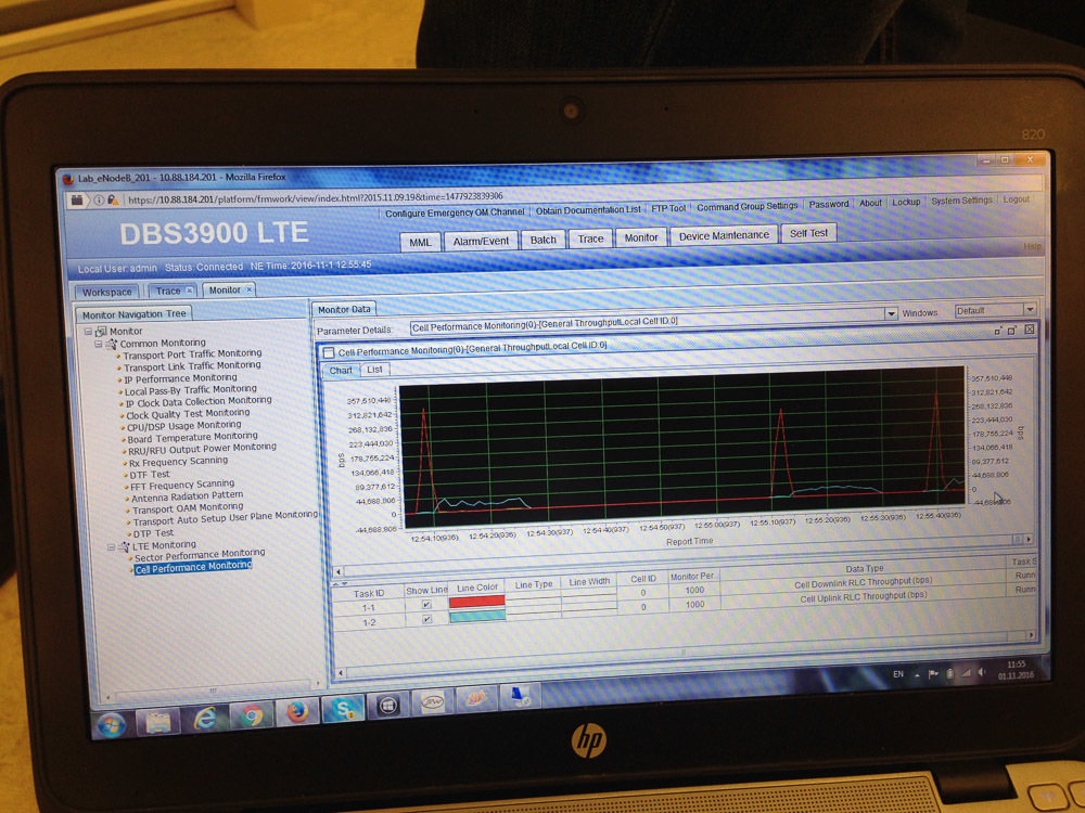
BS control panel confirms record
Leave the shielded rooms and go along thick coaxial cables that go out of each room. They lead to a separate room in which the holy of saints Laboratories are located - base stations and radio heads. Here, for example, BS:
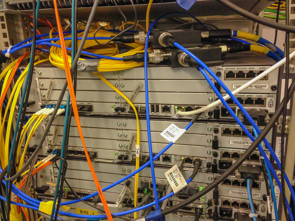
In the racks are BS for 3G and LTE
Thick blue cables are paths from GPS receivers on the roof:
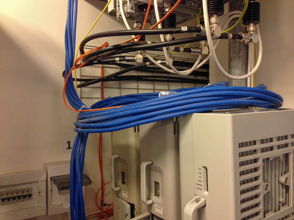
It would seem, why to know the coordinates of the building standing in place?
GPS is used for accurate time synchronization at neighboring base stations - for synchronizing between them the start time of receiving and transmitting. The absence of this synchronization creates interference and interference, even the lack of communication at all.
Yellow wires are fiber, CPRI is an interface for BS communication and a radio head (transmitter). And here are the transmitters themselves:
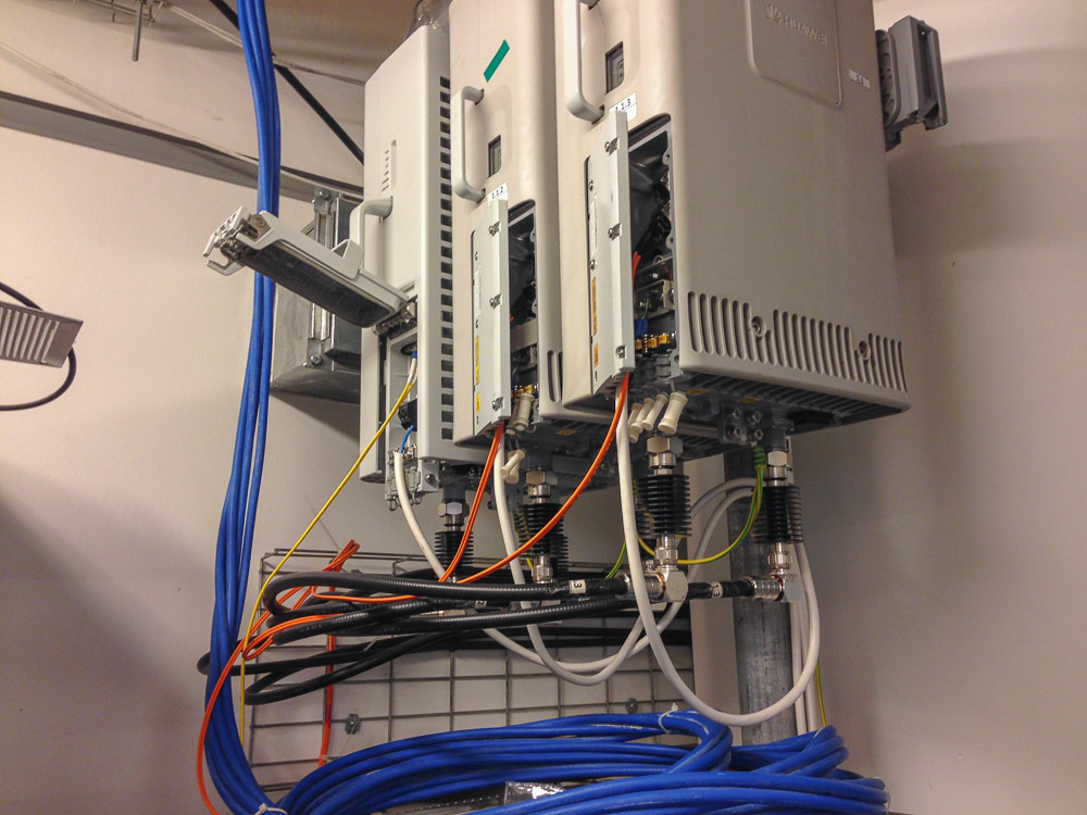
Transmitters of new type, which can be installed next to the antennas
The system is usually divided into a BS control module (pictured above), a transmitter, and an antenna. In older systems, the control module and transmitter were usually in the same rack, and the antenna was connected to the transmitter with a long-long feeder path. In new systems, the transmitter, if obtained, is installed next to the antenna, and is connected to the antenna by a short path. Due to this, the length of the feeder path is saved, the installation is simplified, losses are reduced, and this means that the transmission / reception distance increases.
There are also micro-cells - this is when the control, the transmitter and the antenna are in the same package:
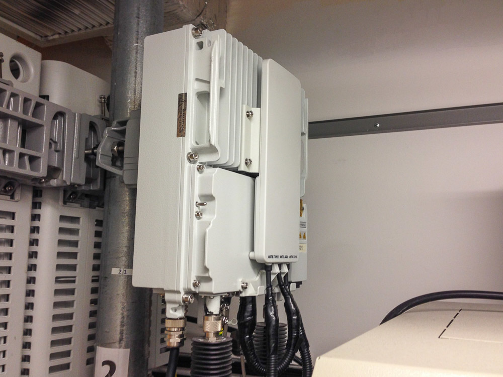
The antenna, however, is disabled so that it can be brought to the shield box
It remains to connect the power, communication, and a full network is ready. Of course, the performance of such a microcell is less than that of a conventional one, but sometimes it suffices.
At the exit of the radio heads are black things - these are attenuators that reduce the signal power.
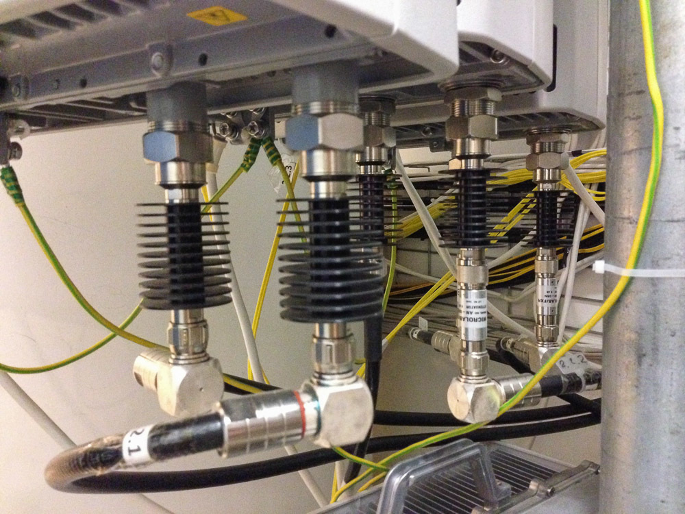
This attenuator reduces the signal power by 10db - 10 times.
The rooms are small, and the BS is powerful, and in order not to become bald ahead of time and not overload the input paths of the devices under test, the output of the transmitter is immediately reduced.
Attenuators are not only small:
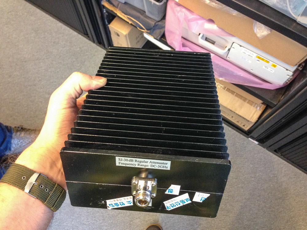
This attenuator reduces the signal power by 30db - 1000 times.
The difference in input and output power is emitted on it in the form of heat, therefore, the larger the rating, the larger the radiator. These attenuators in the first approximation can be considered as resistors for electronics.
After attenuators, the signal goes to the cross-panel, where you can connect the transmitter outputs to the inputs in rooms or shield boxes:
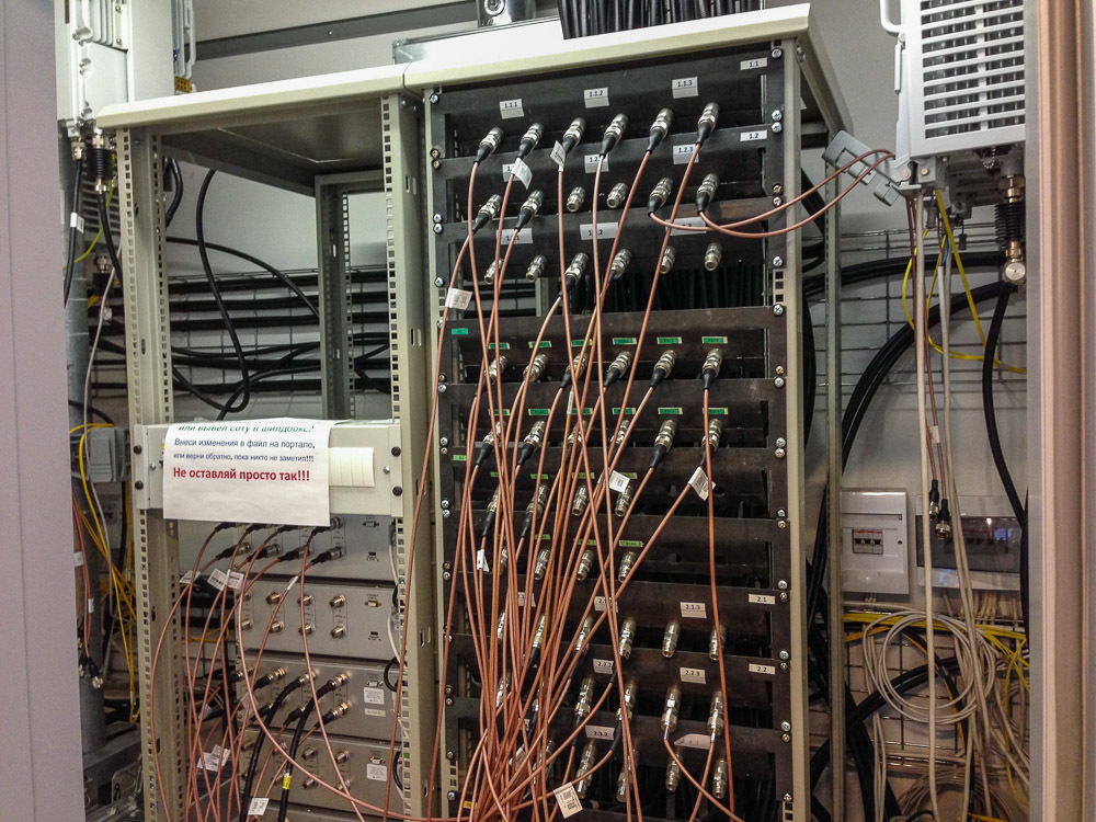
The cross-panel, in fact, is just a set of connectors interconnected by cables
The panel allows you to quickly switch devices between different receivers, without crawling between base stations and without touching their connectors once again.
But the cross-panel allows not only to connect the selected radio head and room. It allows you to switch between them ... another attenuator. Only not simple:
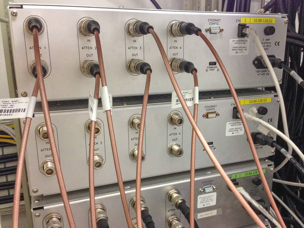
This is a customizable programmable attenuator with control.
It has an Ethernet port, through which it can be commanded, how much it is necessary to reduce the signal level. This allows you to make very complex test patterns, such as smooth switching from one BS to another in poor reception conditions.
For example, this was used when debugging the technology of switching a subscriber device to a more free cell, even if with a worse signal - if the current cell does not cope with such a number of subscribers. It sounds quite simple, but in fact there are a thousand and one subtleties, starting from setting the thresholds of this switch itself, and cell load calculation algorithms (to understand what percentage of subscribers need to be transferred if necessary), ending with explaining the phone why it cannot be returned on this attractive close cell with a strong signal. Such things are very difficult to debug in a real network, and with such tools - easily.
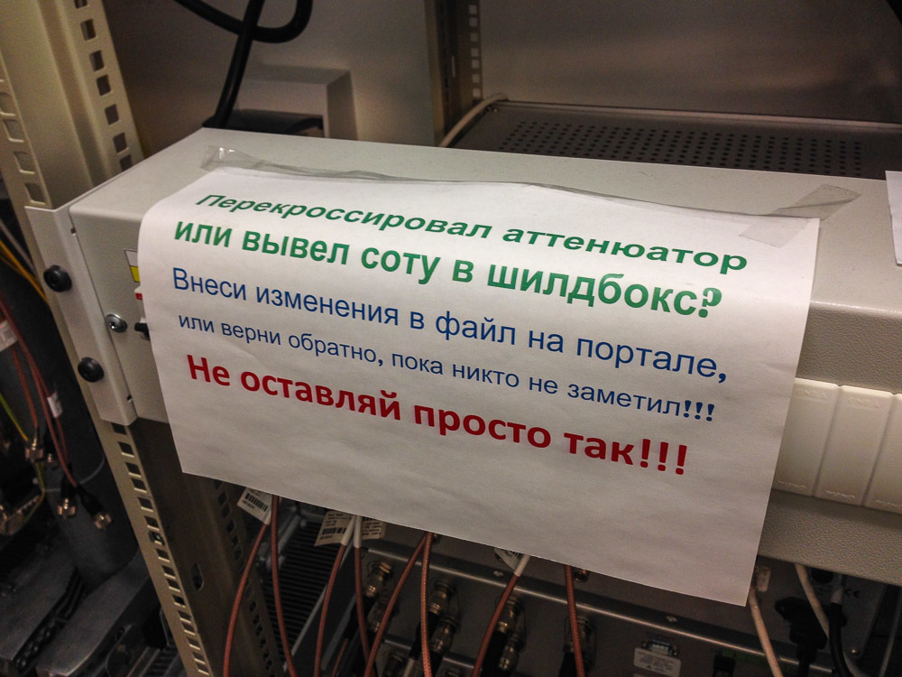
Now you understand the meaning of the ads in the title picture?
And here is the file from the portal in printed form:
By the way, full size is available by clicking
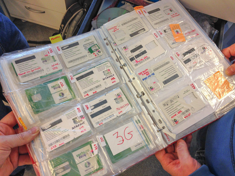
At the end of the story I will show several iron artifacts that we met at the Laboratory.
Entire collections of sim cards:
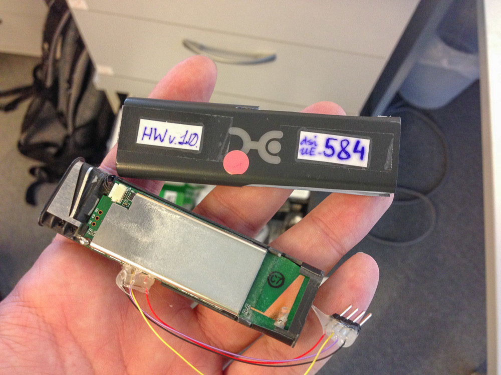
And this is how the early-early prototype of the 3G modem looks like:
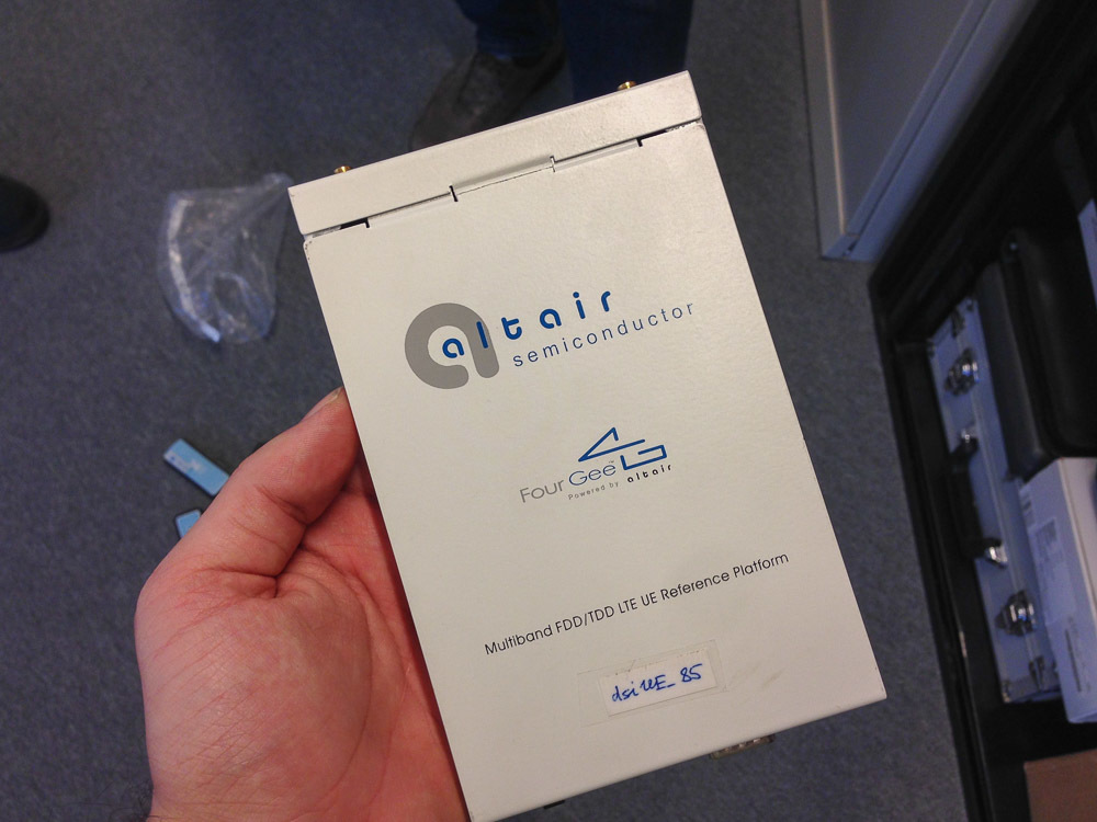
This is only a platform on which different manufacturers can develop their devices.
Unlike them, it has debugging interfaces:

However, sometimes these interfaces have to be connected to release devices:
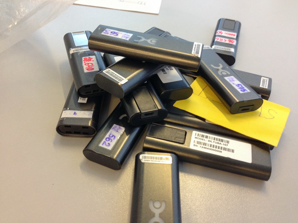
But most often they are tested just like that, and then they fold onto a shelf:
On this tour of the Laboratory can be considered complete. Irina Krylova, a subscriber equipment testing engineer, giggles and says goodbye to you:
Do not understand anything? Nothing, after reading the article will be!
If you are interested - please under the cat!
In general, why does a cellular operator need a laboratory? First of all, such a Laboratory allows reducing maintenance costs without compromising its quality. How is this achieved? In several ways:
')
1) Testing the majority of new mobile technology, before it hits the shelves. According to the results of this testing, firstly, a dialogue begins with the manufacturer, the result of which is fine tuning (as a rule, software) of the radio part of the device to improve its work on the network. Secondly, the decision is made on the admission of devices in their own retail Megafon (all these brand-name stores).
Test world for checking the quality of the phone's cameras, included in the list of 250 tests for any device sold in
2) Studying the device support for new data transfer functions. The fact is that manufacturers of devices (hardware) and programs (so-called device firmware) sell their solutions to telecom operators in very different configurations: from the cheapest with the minimum of functions to sophisticated, with full support for all possible communication standards.
Thus, a small telecom operator somewhere in Indonesia buys a low-cost solution that will be enough for him for a long time - because most of his subscribers still go with push-button dialers, and a large operator in a million-plus city takes a decision with the support of modern standards, otherwise he cannot keep up with race speeds and ensure their subscribers sane quality of work.
In addition, the constant increase in speed is a vital way in the face of increasing number of devices and increasing traffic. The fact is that the bandwidth is divided into all subscribers who are in range. And the faster the subscriber downloads the file he needs, the faster the channel will free up and increase the speed for other subscribers.
BS control panel (base station). In the control panel, you can configure the BS with supported protocols and modesBy the way, the same goal is pursued by the first direction of the Laboratory's work - the better the client device is configured, the less it will interfere with neighboring devices, the less it will consume network capacity, and the faster it will transmit data, which means it will improve the quality of communication for all others subscribers
Thus, the Laboratory saves the operator’s money, allowing him, instead of building additional base stations, to improve communication devices and protocols. And saving the operator’s money is reducing the rate of growth of tariffs for its users.
What is a laboratory?
First, it is infrastructure.
For example, three screened rooms for testing, in which you can create any conditions and combinations of existing networks.
The door to the shielded room. You are the captain yourself.A lot of shield boxes (these are the same things as rooms, only small ones and are put on the table).
Shield box, placed inside the test device
Several base stations: LTE, 3G, 2G.
Radio head BS production Huawei
Secondly, this is an understanding of how to test devices.
For example, when surveying subscribers in stores across the country, it turned out that what matters most for the average customer is not the amount of memory, and not the processor speed, and not the quality of the camera. In the half hour that usually passes from entering the store to buying a phone, the most important thing is how smoothly the interface works and how well the sensor perceives pressing.
It’s not clear how to know it, but how to measure it, because the assessment of “well, norms like” cannot be conveyed to the manufacturers.
Therefore, the Laboratory had to develop from scratch a procedure for testing the phone's sensor, which allowed the subjective assessment to be quantified - points. The procedure tests both the surface mark, the absence of dead zones, the speed of response, positioning accuracy, and so on.
A small part of the devices that have been tested
In the future, this procedure will be included in the global document on the Requirements of the Operator for devices, dedicated to testing protocols and test results, which will be available to mobile device vendors - they will be able to carry out tests on their equipment in advance, saving time. The cycle of passing all tests in the Laboratory ranges from two weeks to a month, after each cycle, the manufacturer sends a test document, he corrects the flaws, and sends them back to testing. Usually, such iterations require from 3 to 10, the Lab hopes that the document will reduce this number at least a couple of times.
Third, these are people. In the process of working here, employees acquire a unique experience with a specific hardware, which is very much appreciated - one person has already left to work at Apple, the other two have been hired by equipment manufacturers - Nokia and Huawei, another one is currently working at Qualcomm. The competence of employees allows them to create such protocols and documents for testing, as described above, which ultimately helps the entire mobile communications industry. In addition, cuties work here:
Maria - Subscriber Equipment Testing Engineer
We were led around the Lab and told more about what is in it.
This is one of the screened rooms (there are three of them).
Rooms differ in the color of the walls - this is the "yellow room"
Do not be deceived by the quite usual appearance - under the layer of finishing there is a shielding metal mesh and special plaster that provide almost complete shielding of the interior of the room from any radiation outside. It does not accept the building's WiFi, you cannot talk on the radio, radio receivers do not work, cellular networks are not caught. An ideal place for people who are “ allergic ” to radio-radiation . Only one problem - the construction of such a room will cost about $ 100,000.
In order to be in this room, you can talk on the phone, here is installed femtocell:
The black block is the femto cell. Such a device in the presence of the Internet to create a network operator anywhere. To ensure that they are not taken away to the resorts of Turkey, they are provided with protection and GPS trackers.
However, by itself, the screened room is useless - if there is no connection, then there is nothing to test. In order to create test conditions in it, radio paths from base stations are entered into it:
In each room there are 4 inputs that can be switched to any BS and their combinations using the cross panel
These pins are connected to the antennas, creating an
Antennas - Gray Quarter Cylinders
Inside the room, usually the current configuration is written on the blackboard, what and where is connected:
Green lab configuration, inter freq, intra freq, sweets for April ... WHAT?
We ask what happened to the candy for April.
They say they were in March. OK. Let's return to our BS
Conclusions from the BS can be connected not only to the rooms, but also to the shieldboxes:
It is written on the shieldbox to which BS it is connected
Shieldbox - this is the same room, only in miniature. It also has several antenna inputs and the antennas themselves inside:
In this box, there are three inputs for antennas, as well as input power, Ethernet, USB, COM-port and PS / 2
The antenna of the shieldbox itself looks like this:
An antenna grid is needed to accurately position it on the device under test, for example, when a radiation pattern is measured.
Some shieldboxes are quite small:
True, they are still expensive
If rooms are used for multiple testing (when a dozen or two devices are hung up on the BS, and they look at how they digest each other), tests on people (talk, hold in hands, test the Internet speed while surfing) Shield boxes are mainly used to test and configure single devices. For example, load testing of Zyxel CPE with LTE-Advanced:
In the photo: Alexander Jakonia (head of the Laboratory), Zyxel (router). Zyxel on the left.
466 Gbit already downloaded:
Usually for testing just download some big file.
But debugging by the Chinese manufacturers of their new WiFi-modem looks like:
On the router, placed in the shield box, the test firmware is flooded, and the router itself is connected to the computer on which the Chinese conjure with the parameters through TeamViewer
From the shieldbox we return to the screened rooms. Today, the iPhone 7 is being tested there - the first of the iPhone on the Russian market, which supports the aggregation of three carriers. 6S supported only two.
Why aggregation?
The meaning of all this carrier aggregation is that at a fixed frequency band it is impossible to increase the speed to infinity - all sorts of MIMOs allow you to stick more data into the range, but at the cost of spending additional processor resources on signal processing, both on the BS and on the phone, and these costs increase exponentially. As a result, to increase the speed it remains only to expand the available frequency band.
True, simply stretching it several times, making 60 MHz from 20 MHz does not work out - first, broadband receivers will cost more (or will require more resources for processing), and second, this is hampered by the fact that the frequencies purchased by operators As a rule, they are distributed over the whole range - 20 MHz there, 10 MHz there. Therefore, the only available way is aggregation of several carriers (Carrier Aggregation - CA), when the BS sends data to the phone in several bands at once in parallel, summing the bandwidth of the channels. By the way, the BS may not spread all the data into several channels, but duplicate the data, thereby improving reception in difficult conditions - where 2.6GHz does not go through, 1800MHz at least somehow, but it will. It all depends on the settings of the BS.
True, simply stretching it several times, making 60 MHz from 20 MHz does not work out - first, broadband receivers will cost more (or will require more resources for processing), and second, this is hampered by the fact that the frequencies purchased by operators As a rule, they are distributed over the whole range - 20 MHz there, 10 MHz there. Therefore, the only available way is aggregation of several carriers (Carrier Aggregation - CA), when the BS sends data to the phone in several bands at once in parallel, summing the bandwidth of the channels. By the way, the BS may not spread all the data into several channels, but duplicate the data, thereby improving reception in difficult conditions - where 2.6GHz does not go through, 1800MHz at least somehow, but it will. It all depends on the settings of the BS.
What is it for? To increase speed, of course. All previous devices supported the aggregation of a maximum of two channels of 20 MHz each, which gave a theoretical ceiling with a maximum speed of 300 mbps. In reality, there were less - about 280. The 10 MHz band is about 70 Mbit speed. Two carriers at 20 MHz, plus a third one with a width of 10 MHz, it turns out (70 + 70) * 2 + 70 = 350mbits. Here, for example, it turned out 330mbit:
If the speed is above 300 Mbps, then it is already above the theoretical limit for two carriers
In general, as I said, this speed is needed not so much by users as an operator - a person doesn’t have much difference, a movie will be downloaded in half an hour or 10 minutes, it’s not difficult to wait, but the operator has it, increasing the speed allows you to provide more subscribers with communication.
BS control panel confirms record
Leave the shielded rooms and go along thick coaxial cables that go out of each room. They lead to a separate room in which the holy of saints Laboratories are located - base stations and radio heads. Here, for example, BS:
In the racks are BS for 3G and LTE
Thick blue cables are paths from GPS receivers on the roof:
It would seem, why to know the coordinates of the building standing in place?
GPS is used for accurate time synchronization at neighboring base stations - for synchronizing between them the start time of receiving and transmitting. The absence of this synchronization creates interference and interference, even the lack of communication at all.
Yellow wires are fiber, CPRI is an interface for BS communication and a radio head (transmitter). And here are the transmitters themselves:
Transmitters of new type, which can be installed next to the antennas
The system is usually divided into a BS control module (pictured above), a transmitter, and an antenna. In older systems, the control module and transmitter were usually in the same rack, and the antenna was connected to the transmitter with a long-long feeder path. In new systems, the transmitter, if obtained, is installed next to the antenna, and is connected to the antenna by a short path. Due to this, the length of the feeder path is saved, the installation is simplified, losses are reduced, and this means that the transmission / reception distance increases.
There are also micro-cells - this is when the control, the transmitter and the antenna are in the same package:
The antenna, however, is disabled so that it can be brought to the shield box
It remains to connect the power, communication, and a full network is ready. Of course, the performance of such a microcell is less than that of a conventional one, but sometimes it suffices.
At the exit of the radio heads are black things - these are attenuators that reduce the signal power.
This attenuator reduces the signal power by 10db - 10 times.
The rooms are small, and the BS is powerful, and in order not to become bald ahead of time and not overload the input paths of the devices under test, the output of the transmitter is immediately reduced.
Attenuators are not only small:
This attenuator reduces the signal power by 30db - 1000 times.
The difference in input and output power is emitted on it in the form of heat, therefore, the larger the rating, the larger the radiator. These attenuators in the first approximation can be considered as resistors for electronics.
After attenuators, the signal goes to the cross-panel, where you can connect the transmitter outputs to the inputs in rooms or shield boxes:
The cross-panel, in fact, is just a set of connectors interconnected by cables
The panel allows you to quickly switch devices between different receivers, without crawling between base stations and without touching their connectors once again.
But the cross-panel allows not only to connect the selected radio head and room. It allows you to switch between them ... another attenuator. Only not simple:
This is a customizable programmable attenuator with control.
It has an Ethernet port, through which it can be commanded, how much it is necessary to reduce the signal level. This allows you to make very complex test patterns, such as smooth switching from one BS to another in poor reception conditions.
For example, this was used when debugging the technology of switching a subscriber device to a more free cell, even if with a worse signal - if the current cell does not cope with such a number of subscribers. It sounds quite simple, but in fact there are a thousand and one subtleties, starting from setting the thresholds of this switch itself, and cell load calculation algorithms (to understand what percentage of subscribers need to be transferred if necessary), ending with explaining the phone why it cannot be returned on this attractive close cell with a strong signal. Such things are very difficult to debug in a real network, and with such tools - easily.
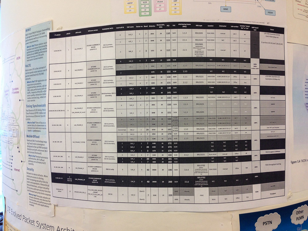
Now you understand the meaning of the ads in the title picture?
And here is the file from the portal in printed form:
By the way, full size is available by clicking
At the end of the story I will show several iron artifacts that we met at the Laboratory.
Entire collections of sim cards:
And this is how the early-early prototype of the 3G modem looks like:
This is only a platform on which different manufacturers can develop their devices.
Unlike them, it has debugging interfaces:
However, sometimes these interfaces have to be connected to release devices:
But most often they are tested just like that, and then they fold onto a shelf:
On this tour of the Laboratory can be considered complete. Irina Krylova, a subscriber equipment testing engineer, giggles and says goodbye to you:
Source: https://habr.com/ru/post/315262/
All Articles