Networks for the harshest. Part twelfth. MPLS L2VPN
How long is it short, but the gears were once again turned around and the linkmeup got up to Tier 2 level. And several sufficient solvency of enterprises showed interest in organizing communication between their branches through the linkmeup network.
L3VPN, which we reviewed in the last release, covers a huge number of scenarios that most customers need. Huge, but not all. It allows communication only at the network level and for only one protocol - IP. How to deal with telemetry data, for example, or traffic from base stations operating via the E1 interface? There are also services that use Ethernet, but also require communication on the data link layer. Again, data centers love to communicate in the L2 language.
Here and our customers take out and put L2.
')
Traditionally, before everything was simple: L2TP, PPTP and all, by and large. Well, in the GRE it was still possible to hide Ethernet. For everything else, they built separate networks, led dedicated lines at the cost of a tank (monthly).
However, in our century of convergent networks, distributed data centers and international companies, this is not a way out, and a number of scalable channel-based Wi-Fi technologies have spilled onto the market.
This time we will focus on MPLS L2VPN.

Before diving into the warm MPLS, take a look at what types of L2VPNs exist at all.
Why is he a winner? The main reason, of course, is the ability of routers that transmit MPLS packets to abstract from their contents, but at the same time distinguish traffic from different services.
For example, an E1 frame comes to PE, is immediately encapsulated in MPLS, and no one along the way will even suspect that there is inside - it is only important to change the label in time.
And the Ethernet frame comes to another port and it can go over the network using the same LSP, only with a different VPN label.
In addition, MPLS TE allows you to build channels based on traffic requirements for network parameters.
In conjunction with LDP and BGP, it becomes easier to configure VPN and automatically find neighbors.
The ability to encapsulate traffic of any data link layer in MPLS is called AToM - Any Transport over MPLS .
Here is a list of AToM supported protocols:
To build any L2VPN there are two conceptually different approaches.
Traditionally, terms will be entered as needed. But about some at once.
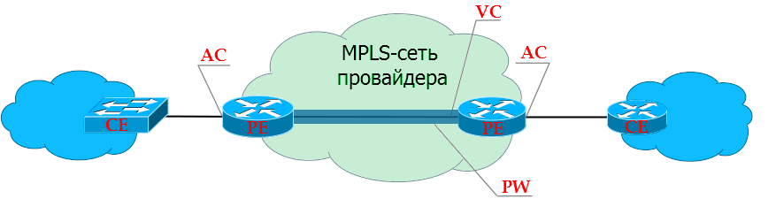
PE - Provider Edge - provider's MPLS network edge routers to which client devices (CE) are connected.
CE - Customer Edge - customer equipment that directly connects to the provider's routers (PE).
AC - Attached Circuit - PE interface for client connection.
VC - Virtual Circuit is a virtual unidirectional connection through a common network that simulates the original environment for the client. Connects to each other AC-interfaces of different PE. Together they make up a one-piece channel: AC → VC → AC.
PW - PseudoWire - a virtual bidirectional data link between two PEs - consists of a pair of unidirectional VCs. This is the difference between PW and VC.
VPWS - Virtual Private Wire Service .
At the heart of any MPLS L2VPN solution is the idea of PW - PseudoWire - a virtual cable that is routed from one end of the network to the other. But for VPWS, this PW itself is already a service.
A kind of L2-tunnel through which you can safely pass anything you want.
Well, for example, the client has a 2G base station in Kotelniki, and a controller in Mitino. And this BS can only connect via E1. In ancient times, I would have to stretch this E1 with the help of cable, radio circuits and all kinds of converters.
Today, one common MPLS network can be used for both E1 and L3VPN, the Internet, telephony, television, and so on.
(Someone will say that instead of MPLS for PW, you can use L2TPv3, but who needs it with its scalability and lack of Traffic Engineering?)
VPWS is relatively simple, both in terms of traffic transmission and the work of service protocols.
The tunnel tag is the same as the transport tag, just the long word “transport” did not fit into the heading.
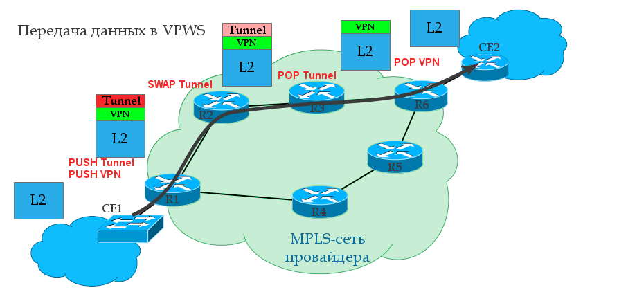
0. A transport LSP is already built between R1 and R6 using the LDP or RSVP TE protocol. That is, R1 is known transport label and output interface to R6.
1. R1 receives from the client CE1 some L2 frame on the AC interface (it may be Ethernet, TDM, ATM, etc. - it does not matter).
2. This interface is tied to a specific client identifier — the VC ID — in a sense, an analog of the VRF in L3VPN. R1 gives the frame a service tag, which remains unchanged until the end of the path. The VPN label is internal to the stack.
3. R1 knows the destination point - the IP address of the remote PE router is R6, finds out the transport label and inserts it into the MPLS label stack. It will be external - transport label.
4. An MPLS packet travels through the operator’s network through P-routers. The transport tag is changed to a new one at each node, the service tag remains unchanged.
5. On the penultimate router, the transport tag is removed — PHP happens. R6 comes with a single VPN service tag.
6. PE2, having received the packet, analyzes the service tag and determines which interface to transfer the unpacked frame to.
If you read the previous release about L3VPN , then you will not see anything new in the issue of the transmission of user traffic - a pair of MPLS tags and transmission over the transport LSP. Ingress PE checks which tags to put and which interface to send, P changes the transport label, and Egress PE takes the VPN label to decide which AC interface to send the received frame to.
The transport label can be assigned as LDP (see the MPLS release ), and RSVP-TE (still waiting in the wings).
For example, take LDP — this protocol is launched across the entire network, which for each Loopback address of each MPLS router will distribute tags over the network.
In our case, R1 after LDP operation will, roughly speaking, know 5 tags: how to get to each of the remaining routers.
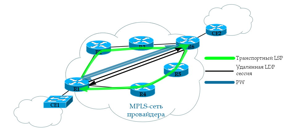
We are interested in LSP R1 → R6 and back. Note that in order for the VC to transition to the UP state, both LSPs must be forward and reverse.
There are several different ways to implement a VPWS service. We will talk about this below, and for example we will analyze the one that is most often used now.
For the distribution of service tags is the same LDP, only genetically modified - Targeted LDP . Now he can establish a connection with remote routers and exchange tags with them.
In our example, clients are connected to R1 and R6. R1 through LDP will report its label to this R6 client and vice versa.
At both ends, we manually configure a remote LDP session. It is not tied to the VPN. That is, the same session can be used to exchange tags with any amount of VPN.
A regular LDP is a link-local protocol and looks for neighbors among directly connected routers, that is, the TTL of its packets is 1. However, tLDP has sufficient IP connectivity.
As soon as AC-interfaces with the same VC-ID appear on both sides, the LDP will help them communicate the tags to each other.
What is the difference between tLDP and LDP?
In order not to run far away, immediately practice.
Simplify the topology to four trunk nodes. By clicking, you can open it in a new tab, to look at it with Alt + Tab, rather than turning the page up and down.

Our task is to run Ethernet from Linkmeup_R1 (port Gi3) to Linkmeup_R4 (port Gi3).
In step 0, IP addressing, IGP routing, and basic MPLS are already configured (see how ).
Let's follow what was going on behind the scenes of the protocols (the dump was removed from the GE1 Linkmeup_R1 interface). There are major milestones:
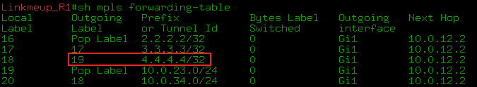
0) IGP converged, LDP identified neighbors, raised the session and distributed transport tags. As you can see, Linkmeup_R4 allocated a transport label 19 for FEC 4.4.4.4.
1) But tLDP has begun its work.
--BUT. First, we configured it to Linkmeup_R1 and tLDP began to periodically send its Hello to the address 4.4.4.4
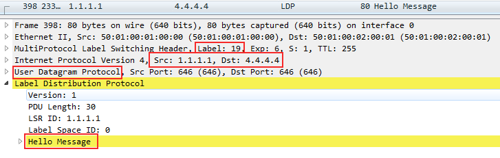
As you can see, this is a unicast IP packet that is sent from the address of the Loopback interface 1.1.1.1 to the address of the same Loopback of the remote PE - 4.4.4.4.
Packed in UDP and transmitted with one MPLS - transport tag - 19. Pay attention to the priority - the EXP field - 6 is one of the highest, since it is a service protocol packet. We'll talk more about this in the QoS issue.
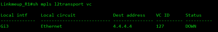
The PW status is still in DOWN, because there is nothing on the back side.
--B. After setting up xconnect on the Linkmeup_R4 side, immediately Hello and establishing a TCP connection.
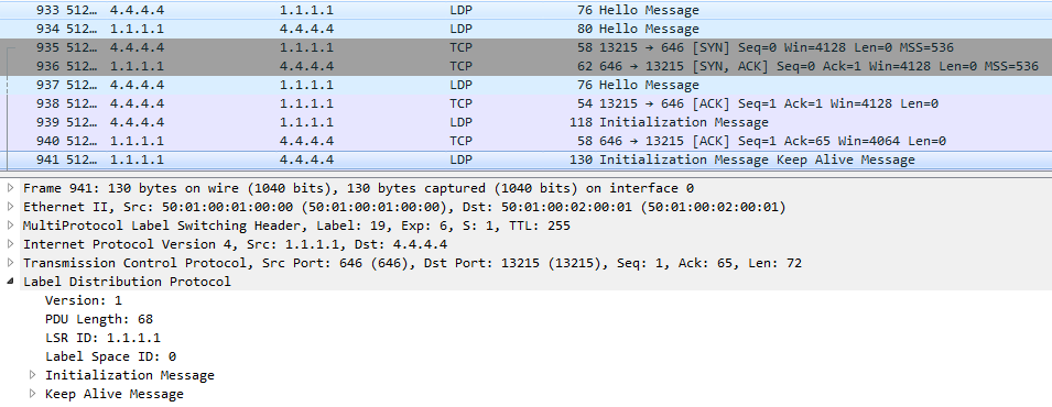
At this point, the LDP-neighborhood is established:
--AT. I went exchange tags:
At the very bottom, you can see that the FEC in the case of VPWS is the VC ID that we specified in the xconnect command — this is our VPN identifier - 127 .
And just below it, the Linkmeup_R4 tag allocated to it is 0x16 or 22 in the decimal system.
That is, with this message Linkmeup_R4 reported Linkmeup_R1, they say, if you want to transfer a frame to a VPN with VCID 127, then use the service tag 22.
Linkmeup_R1 does the same thing - Linkmeup_R4 informs its label:
After that, the VCs are raised and we can see the labels and current statuses:
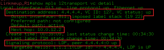
The show mpls l2transport vc detail and show l2vpn atom vc detail commands are generally identical for our examples.
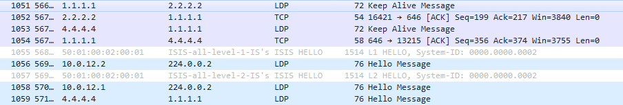
2) Next, the neighbors will only maintain contact:
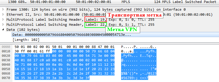
3) Now everything is ready to transfer user data. At this moment we launch ping. Everything is predictable simply: two tags that we have already seen above.
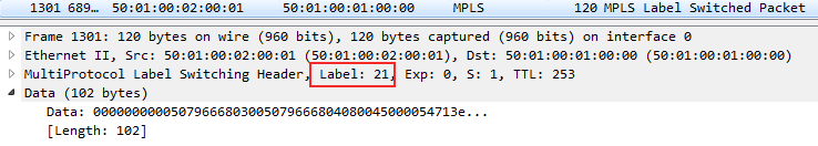
Accordingly, ICMP-Reply is returned only with the VPN label, because PHP has taken the place of Linkmeup_R2 and the transport tag has been removed.
If the VPWS is just a wire, then he should calmly transmit a frame with a VLAN tag? Yes, and for this we do not have to reconfigure anything. Here is an example of a frame labeled VLAN:

Here you see the Ethertype 8100 - 802.1q and a VLAN tag of 0x3F, or 63 in the decimal system.
If we transfer the xconnect configuration to the subinterface with the VLAN indication, then it will terminate this VLAN and send a frame without the 802.1q header to the PW.
The considered example is EoMPLS (Ethernet over MPLS). It is part of the PWE3 technology, which is the essence of the development of VLL Martini Mode. And all this together is VPWS. The main thing is not to get lost in the definitions. Let me be your guide.
So, VPWS is the common name for point-to-point solutions for L2VPN.
PW is a virtual L2 channel that underlies any L2VPN technology and serves as a tunnel for data transmission.
VLL (Virtual Leased Line) is already a technology that allows you to encapsulate frames of various data link layer protocols in MPLS and transfer them through the provider's network.
PWE3 - Pseudo Wire Emulation Edge to Edge . Strictly speaking, the scope of this technology is wider than just MPLS. However, in the modern world in 100% of cases they work in conjunction. Therefore, PWE3 can be considered as an analogue of Martini VLL with enhanced functionality - LDP + tLDP is also engaged in signaling.
Briefly, its differences from Martini VLL can be represented as follows:
Now PWE3 is a de facto standard and it was he who was in the example above.
I really like the term point-multipoint. There is something childish in it, playful. And this is what we will talk about now.
VPLS - Virtual Private LAN Service. At its core, it is a switch. The provider connects several customer points to its network at its different ends and provides L2 connectivity. And now it’s the task of the provider’s transport network to take care of correct frame switching, that is, learning MAC addresses.
VPLS-domain is an isolated L2 virtual network, that is, roughly speaking, one separate L2VPN. Two different clients - two different VPLS domains.
VSI - Virtual Switching Instance . Virtual switch within one node.
For each client (or service) he has his own. That is, traffic from different VSIs cannot migrate from one to another.
Analog VRF / VPN-instance in L3VPN.
In Cisco terms, this is VFI - Virtual Forwarding Instance . I allow myself to be free to use the terms VPLS-domain, VSI and VFI, sometimes using them as synonyms.
VE - VPLS Edge - PE node, member of the VPLS domain.
In general terms, the transmission of user traffic looks the same as for the VPWS case, but a step is added to study MAC 's and check the MAC table during traffic transmission.
As in a conventional switch, the records in the MAC table of the VSI periodically fade and delete.
When it comes to learning MAC addresses in the VPLS, there is one thing that makes it very different from L3VPN. PE should not just know the physical port where the frame came from - it is important to define a neighbor or, more precisely, PW as a virtual interface. The fact is that the client frame needs to be sent not just to some physical port, but to the correct PW, in other words, to the right neighbor.
For this purpose, each neighbor is given a personal tag with which he will send a frame to this PE in this VPLS domain. And later on the VPN tag, looking at the LFIB, PE finds out which neighbor the frame came from.
Let me remind you that L3VPN no matter where the IP packet came from, so the same tag is reported to all neighbors for the prefix in the VRF.
The delivery scheme for user traffic is straightforward. But what about the notorious Control Plane? Again, have to break the brains or small victims?
Sorry, but then begins trash and sodomy. Not immediately - later, but there will be. You act at your own risk.
From the work of Data Plane, it is already clear that VPLS requires a fully connected PE topology for each VSI. Moreover, not all PE MPLS networks of the provider will be neighbors, but only those with the same VSI.
Therefore, one of the main issues in VPLS is the detection of all PEs where the clients of this VSI are connected. There are two approaches here: manual tuning and automatic detection . The first way was originally proposed by Cisco (Draft Martini), the father of the second is Juniper (Draft Compell).
11 issues SDSM promoted the simplification of the engineer’s life and the automation of everything. And so, that moment came when you need to forget everything that you were taught. This is the first case (if you don’t raise holivar around VTP) when the solution with manual configuration of the neighbors is more popular.
Became interesting?
Before we open the scenes, I want to make a remark: no matter what we get up with VPN tags, transport LSPs are built as usual LDP or RSVP-TE. Therefore, further we will deal with transport only in passing.
Likewise, regardless of the mode used, the VPLS falls apart at a point-to-point PW. That is, we do not have some kind of centralized cloud switching, but simply a set of virtual lines between all neighbors. The frame transfer decision is made by Ingress PE or, more simply, selects the desired PW.
At the beginning of the two thousandth industry strenuously took up the search for solutions for L2VPN across the operator. The criteria were as follows:
Luca Martini - a former Cisco employee - provided this unannounced tender with an LDP-based solution.
It will work over the MPLS network.
Label signaling will use LDP, which is already part of MPLS. VPLS Martini Mode is described in RFC4762 standard.
It is this laconic solution that has become the de facto standard in most networks around the world. We already met about how the Martini-mode works in the part about VPWS. Exactly the same here, only remote LDP sessions are created for each VSI, not with one neighbor, but with several.
LDP is used to distribute service tags. Remote sessions with each neighbor in the VPLS domain are configured manually. Since all the participants of this VPLS are known in advance, each of them has an LDP assigned an individual label in the LDP Label Mapping Message.
If a new PE is added to the VPLS domain, you need to configure the LDP neighborhood with all existing PEs of this VPLS. After that, with each of them a new PE will exchange tags.
At all times, the LDP checks the availability of its neighbors. If one of the neighbors leaves the group or becomes unavailable, the session is broken and all the studied MACs in PW to this neighbor are cleared.
If the state of any of the AC ports of the VPLS domain goes to the Down state, or another event occurs that causes the MAC addresses to be cleared from the AC port, then PE notifies all its neighbors by insisting that the MAC addresses be removed in the LDP message MAC Withdraw (Unfortunately, CSR1000V on the test bench does not do this).
Let us analyze the work of the VPLS in practice in steps here according to this scheme. This is still the same network, but now the client has decided that two points are not enough for him, he wants four and combine them all into one network.

Clickable
So at step 0 , we have the necessary transport LSPs ready and, accordingly, the routing and so on.
What happened?
1. LDP . LDP bridge-domain — , AC- ( .).
Linkmeup_R1 Linkmeup_R3:
FEC 63 — VPN. 0x18 ( 24).
, Linkmeup_R3 VFI AC-, Linkmeup_R1, VPN- 24. — 17.

, Linkmeup_R1 — , MAC- .
2. Blue-A, ( Gi1 Linkmeup_R1) ARP-:
Since it is broadcast, after it you can see its exact copy with only one difference - VPN and transport tags:
One frame was sent to Linkmeup_R3, the other - to Linkmeup_R4.
3. In the MAC table we can see the MAC address of the Blue-A node (AABB-CC00-0700) - it is located behind the GE3.EFP10 port (Ethernet Flow Point and Service instance 10 ) - and the MAC corresponding to the IP address 192.168.0.2 (AABB -CC00-0300) - for the Pseudoport Blue.100401a interface .
, . — VPLS MAC' PE, Data Plane.
:
Martini mode:
— Juniper. , , MBGP , L3VPN, .
, VPNv4 , VPLS. Route Target . - , Martini Mode.
VPLS Kompella-mode — VPLS Auto-Discovery, Martini. VPLS BGP Signaling.
Control Plane :
—
- Transfer route information and the exchange of tags.
There was nothing new to invent. The neighbor discovery scheme already used in L3VPN works great here.
Route Target, which is the Extended Community - the main sign of belonging to a particular VSI. Roughly speaking - if the RTs match up - it means in one VSI.
Strictly speaking: If the RT of the received announcement coincides with that configured in VSI, then this VSI wants to know the information from the announcement.
As in L3VPN, you can flexibly organize interaction between different VSIs. But so rarely does anyone do.
VSI RT.
BGP VPLS Address Family: L2VPN AFI (25) VPLS SAFI (65)
PE, - VPLS-. , VSI.
RR, .
BGP L2- PE VSI, BGP Update , , . , L3VPN — vpnv4- PE.
PE BGP Update, RT NLRI , VSI.
, PE VSI. — .
Auto-Discovery.
- , VPLS- , - .
In general, the L2VPN prefix is a rather artificial thing - PE, with its BGP Update, rather, reports the fact of its participation in the VPLS domain and the label of this fact. But it does not play a big role.
Any addresses, especially MAC, in the NLRI field of the message BGP Update VPLS does not transmit. Remember that learning MAC addresses is a complete Data Plane feature .
However, it is still necessary to distinguish between announcements of different VSI, so the familiar Route Distinguisher is also present. Usually it is made automatically from the AS number and VPN ID.
However, what is passed to the NLRI? Only label and RD? Not really:

Formally, the prefix is an RD + node sequence number in the VPLS domain + tag box .
" — . — "? VPLS Kompella mode . PE — .
, - , — . , , , — .
, :
Let me remind you that VE - VPLS Edge - the boundary of the network VPLS - PE-router on which VPLS is running.
Before I hit upon all the serious about formulas and values, I consider myself obliged to explain on the fingers in general how it works, because I spent a lot of time and nerves to figure it out.
When a L2VPN frame arrives at the PE from the MPLS network, you need to know exactly which neighbor it is from — it’s necessary to learn the MAC address, so as in the case of the Martini mode, the basic idea is that each neighbor's PE is in a specific VSI must report a unique tag to see who the frame came from.
Look at this simple picture in more detail:
Let R1 be the main one.
0. In Kompella mode, R1 does not explicitly pass the label to its neighbors R2 and R3.
1. Instead, he informs them from which range the labels should be selected to identify the given VC.
2. Each PE has its own sequence number n in the VPLS domain. Knowing yournumber and range of tags, neighbors calculate the outgoing service tag: count n-th in a row from the beginning. That is, R2 took the second (2), and R3 - the third (3).
3. R2 and R3 communicate their R1 numbers, and it also calculates which incoming service tag will be from R2, which is from R3, counting from the beginning of the range 2 and 3.
4. Similarly, R2 and R3 define their own ranges and communicate them to each other and R1. And the cycle of calculations is repeated.
5. In the end, everyone will know the outgoing tags for this VPLS and incoming tags.
Now the second iteration : digging deeper, what kind of matan lies under this simple idea.
The VE ID is manually configured - this is the PE router ID in the VPLS domain (its sequence number). Must be unique within one VSI.
LB - Label Base is the beginning of the range, the first label that can be used.
VBS - VE Block Size is the length of the block of tags - or, more simply, the minimum number of tags in this VSI. For Cisco, the default is 10. For Juniper - 8 (may be reduced to 2 or increased).
This is what the label set will look like: {LB, LB + 1, .., LB + VBS-1}.
In general, the scheme is simple:
VE ID 100-109 is taken from the balda for example
. This animation shows the process of label distribution on PE1: If PE Xwants to send traffic to PE1, it must use the appropriate X label .
Here's another example for PE5:
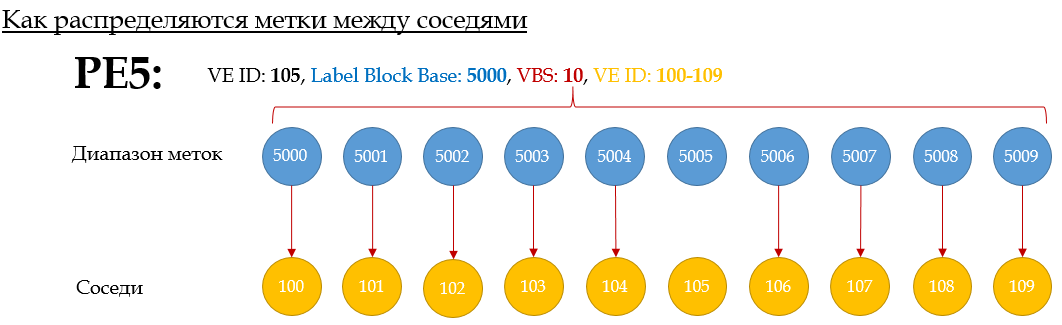
Tags are allocated in order — the first of the block — to the neighbor with the lowest VE-ID. The second - the second largest, and so on.
That is, such a situation is impossible :
However, if the allocated number of labels is small, then the VBO - VE Block Offset parameter - the block offset - will help . It allows you to create multiple blocks. And those neighbors who did not have enough, tags are distributed on the same principle, but from a new unit, with a new LB.
The required VBO is calculated using the formula: VBO = WHOLE (VE-ID / VBS) * VBS.
, VBO — , , VE. — , — .
, , {LB, LB+1,… LB+VBS-1}, LB VBO. <LB, VBO, VBS>

: VE ID (VBO+n) (LB+n).
— .
. VBS — 10. VE-ID : PE1 — 101, PE2-102,… PE 10 — 110. PE1 PE5.
1. PE1 Label Base 1000 — 1000-1009 — , .
2. PE1 VBO. VBO=(101/10)*10=100 .
3. PE1 BGP Update : LB: 1000, VBS:10, VBO:100, VE-ID:101 . RD, RT, . PE1 — Update .
4. BGP Update PE1 PE5. VE-ID: 105 . VSI ( RT BGP Update) PE1.
5. , PE5 — , , PE1. VBO. VBO ≤ PE5 VE-ID ≤ VBO+VBS-1. 100≤105≤109. I will explain. PE1 , ID 100-109 ( 100 10) — VE ID .
6. PE5 , (PE1 LB + PE5 VE-ID — VBO) = (1000 + 105 — 100) = 1005 . , , LB , VE-ID VBO. , PE5, L2 VSI PE1 MPLS- VPN- 1005. PE1 , 1005 — , PE5. VE ID.
7. PE5 BGP Update (, 7 — . PE5 BGP Update ).
8. PE1 VE-ID ( BGP Update), VSI. :
9. But that's not all. PE1 should now calculate the outgoing label to PE5. And all the data he has for this.
(PE5 LB + PE1 VE-ID - VBO) = (5000 + 101 - 100) = 5001 . That is, when sending frames to this VSI to PE5, PE1 will insert a 5001 VPN tag into them
. 10. PE5 calculates incoming: (PE5 LB + PE1 VE-ID - VBO) = (5000 + 101 - 100) = 5001 .
This is what I call mutual assistance!
Unfortunately, quite obvious and at the root of my logical mechanism I can only describe in such a complex language.
PE10, PE. , 100-109 VE ID 110 . VBO 110=(110/10)*10 . LB 10000 .
PE10 PE5, : 110 ≤ 105 ≤ 119.
.
1. PE5 LB 5030 , VBS PE10 — 10 .
2. PE10,
3. PE5 PE10 BGP Update, : — , — LB: 5030, VE ID: 105, VBS:10, VBO:110 .
4. VE-ID PE10 110-119,
5. PE , PE10. .
Label Block : Juniper .
. - 10 PE (9 — PE). -, , VE-ID, , . -, VE-ID VE-range! , MPLS !
, , LDP MBGP L3VPN.
, , RFC 4761 ?
, Control Plane.
, . , , , , . , , CCIE .
- Auto-discovery ( ) L2, MAC-. L3VPN, .
So how does Auto-Discovery work in L3VPN? Some PEs try to tell the whole world about two things - firstly, what prefixes he knows, secondly, to whom they are intended. And he wants to tell everyone about it at once indiscriminately - everyone who is his MBGP neighbors will receive his Update, and RT will see if these announcements are interesting to them. To no - and no trial - will be discarded. And if they are interesting, then the received prefix and its VPN tag will be placed in their VPN routing table.
All the same is true for L2VPN. Except for one: learn MAC addresses . BGP in L3VPN tells everyone the same label — it makes no difference to him where the data packet comes from, his main concern is to transfer it to the correct client interface.
VPLS. , MAC- , . , .
- . BGP Auto-Discovery , .
, -, BGP , Update VPLS-, , .
, «-» (), , «-». -, . when there is no RR, and one PE can send another Update addressable. Then each PE will receive only its message and only its own label. But the reality is that RR has become its (reality) part and, having a neighborhood only with RR, PE sends Update to it, and it sends to all its customers. And if PE sends several Update'ov, then they all scatter on all. It turns out that each of his neighbors will receive not only their own label, but also all the others who have not surrendered to him for nothing.
Just imagine a dump in which you see a hundred Update'ov for left devices.
And here the mechanism of automatic calculation of tags comes to the fore, as a very elegant solution to this problem. It is worth paying tribute to the flexibility of Kiriti Compell’s thought.
And you know, until this concept of a block of tags formed into a consistent set of synapses in my brain, I disregarded it. She seemed clumsy and outdated to me. Something like DVMRP . But now I was inspired by the idea and even somewhat surprised that there is no intelligible explanation anywhere.
I would also note that the situation with the lost labels was somewhat revised with the release of RFC 6624 (in which, by the way, Compella also took direct part)
, LDP-Signalling + BGP Auto-Discovery . — , .
:
What happened?
0. CE
1. BGP Update'.
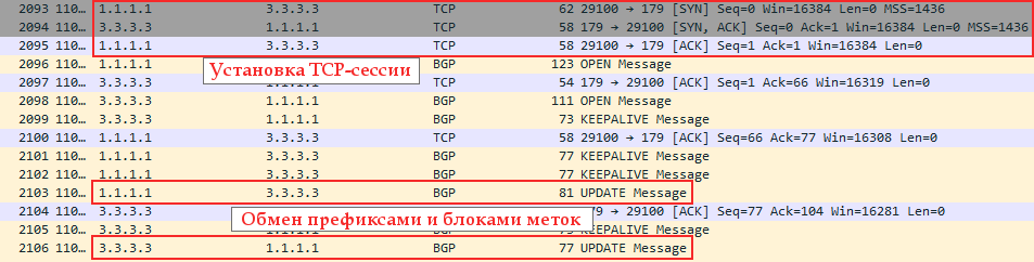
Update NLRI
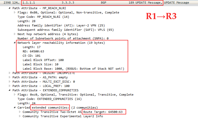
Linkmeup_R1 Linkmeup_R3, VPN- , VPLS RT 65400:63. CE-ID ( VE ID)=101, VBO=100, VBS=10, LB=1000.
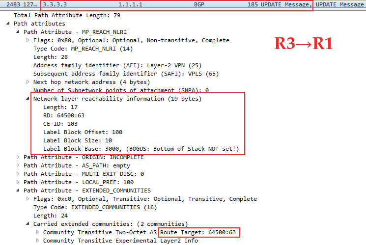
Linkmeup_R3 Linkmeup_R1: CE-ID=103, VBO=100,VBS=10, LB=3000
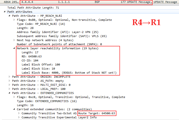
Linkmeup_R4 Linkmeup_R1: CE-ID=104, VBO=100,VBS=10, LB=4000
Linkmeup_R1 Linkmeup_R4 , Linkmeup_R3 .
, PE, , ?
2. PE.
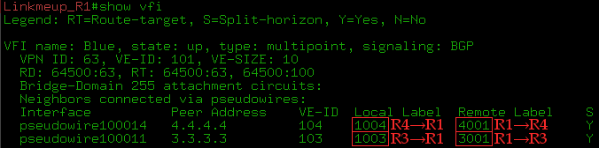
, , . , , . , — , , , .
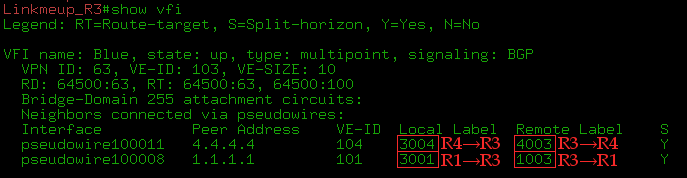
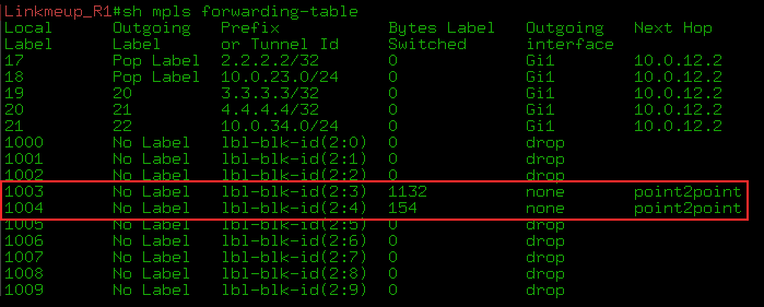
3. , ping Blue-A Blue-D, VPN- 3001 ICMP-Request 1003 ICMP-Reply:
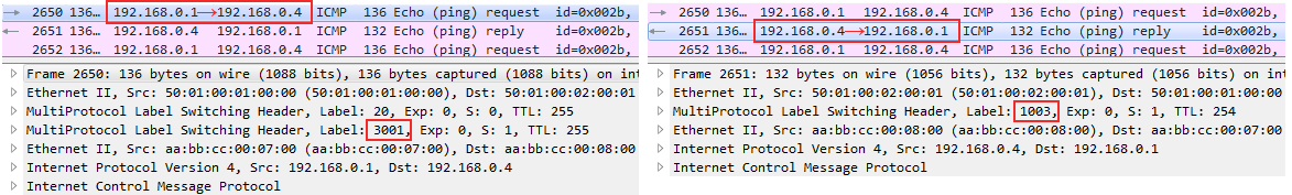
Wireshark - ICMP MPLS
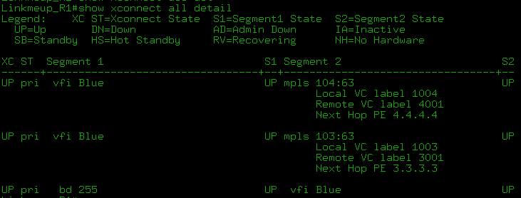
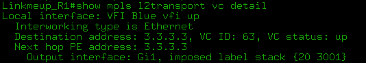
- show mpls l2transport vc detail show l2vpan atom vc detail :
show bgp l2vpn vpls rd X ve-id Y block-offset Z .
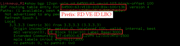
:
, Martini, , :
1) . PE VPLS-, ( RR). Martini PE VPLS-.
2) — VE ID. BGP ( RR).
:
VPLS Kompella mode Juniper: . : cisco .
, BGP Kompella mode Martini Mode?
? .
(Inter-AS) VPN Martini VPLS — PE- VPLS-. H-VPLS . .
Auto-Discovery Kompella , :
- , . , , .
. , NMS.
- , RFC 4762 Auto-Discovery Martini. RADIUS BGP.
, cisco LDP + BGP Autodiscovery autodiscovery LDP signaling BGP l2vpn vfi . , ( BGP ).
Martini .
, , Martini Mode , , - . .
VPLS, .
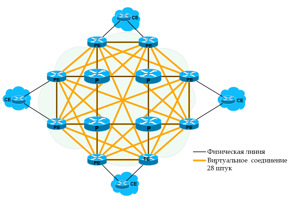
VPLS — — . Kompella mode RR , Martini Mode — LDP-. O(n^2): n*(n-1)/2 — n — .
— Ethernet — , PE.
- BGP- Route Reflector'?
. — H-VPLS (Hierarchical VPLS), RFC 4762 .
H-VPLS VPLS- : PE-rs MTU-s.
PE-rs — PE — routing and switching . VPLS. , PE. PE-rs: PE-POP , n-PE .
MTU-s — Multi-Tenant Unit — switching . , PE-rs . CE. MTU-s: u-PE , PE-CLE .
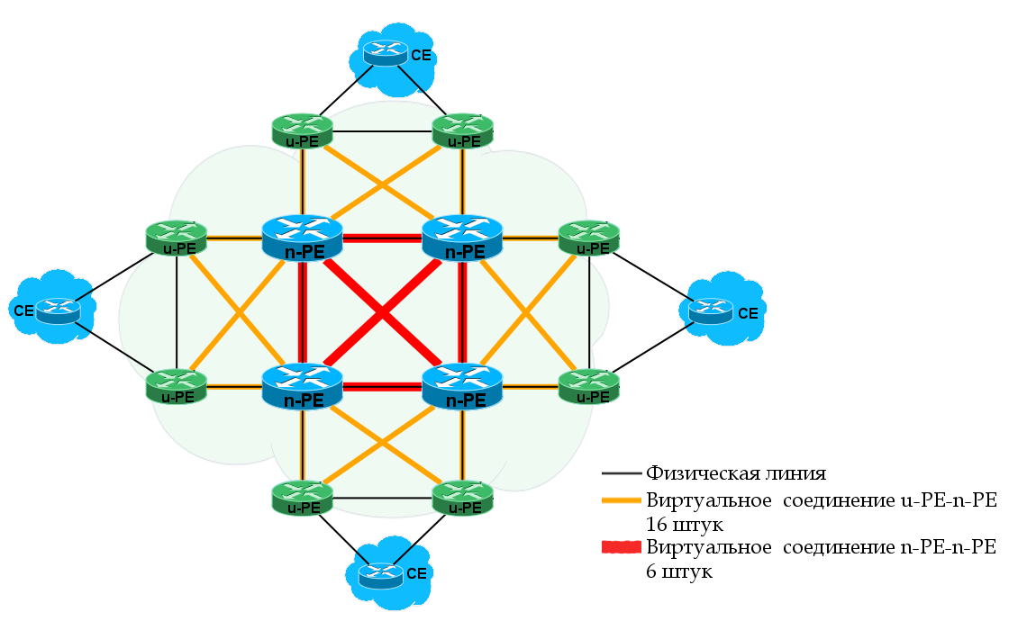
MTU-s PE-rs — . . MTU-s PE-rs: MPLS PW QinQ. MPLS, .
PE-rs PE, .
PE-rs MTU-s, PE-rs PW MTU-s AC-, , . :
— , PE-rs MTU-s PE-rs MTU-s,
— , PE-rs PE-rs MTU-s, PE-rs.
, MTU-s ( ) , PE-rs , . PE-rs.
Inter-AS VPN H-VPLS . , ASBR PE-rs .
H-VPLS — :
! , MAC- PE-rs? , VPLS P, H-VPLS PE, , — MAC-. MTU-s, . .
, , Control Plane Data Plane. , H-VPLS . MAC- , , CPU . H-VPLS .
, , , .
, ?
Dual-Homing'. , Linkmeup_R1 MTU-s, Linkmeup_R2 — PE-rs.
H-VPLS Kompella, , Martini.
What happened? PW :
VFI Linkmeup_R2 :
MAC' :
H-VPLS , :
: H-VPLS PE-rs Redundancy for QinQ Access VPLS Multihoming Juniper tutorial .
L2 c .
- — , .
, . - , MAC- . VPLS-. , , --.
, , QoS, , . , .
- , . . :
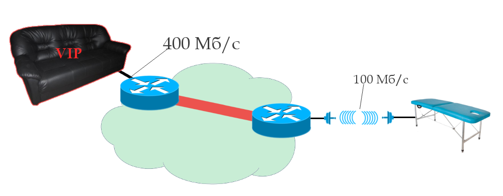
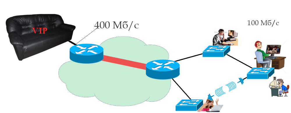
, 100 /. .
, - MAC- . VSI, MAC- , . , , 400 /, 400 / , 100 / . MAC-. .
. , . -. , , , , .
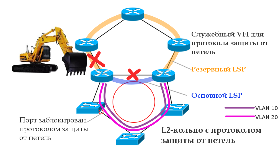
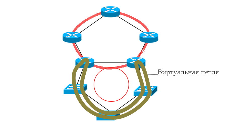
, , , - : STP - . — . - , , .
— , . CS6/CS7, . — , , , ? 100 / , .
, .
. . .
, PE PW ( ). — , MPLS-.
, .
— , , VSI.
, . , .
, , PE , PW Down, . , ( ) . ? , PE , VSI. . PE , .
VPLS PE. , DCI . 1 PE — Dual-Homing — Active/Active — . — .
, . . , 1 , .
, . L2. PE1 MAC- — , 1 PE2, MAC-. , -.
, — . , «», , Ethernet — — . — — , .
, , , L2, , , L3VPN. , - . , , .
, . Ethernet, .
— EVPN. , MAC- Control Plane BGP.
, . : .
Luc De Ghein. MPLS Fundamentals 1st Edition . Ina Minei, Julian Lucek. MPLS-Enabled Applications: Emerging Developments and New Technologies 3rd Edition .
, .
, , linkmeup .
Thanks
» , JDima .
» .
» .
» , , .
L3VPN, which we reviewed in the last release, covers a huge number of scenarios that most customers need. Huge, but not all. It allows communication only at the network level and for only one protocol - IP. How to deal with telemetry data, for example, or traffic from base stations operating via the E1 interface? There are also services that use Ethernet, but also require communication on the data link layer. Again, data centers love to communicate in the L2 language.
Here and our customers take out and put L2.
')
Traditionally, before everything was simple: L2TP, PPTP and all, by and large. Well, in the GRE it was still possible to hide Ethernet. For everything else, they built separate networks, led dedicated lines at the cost of a tank (monthly).
However, in our century of convergent networks, distributed data centers and international companies, this is not a way out, and a number of scalable channel-based Wi-Fi technologies have spilled onto the market.
This time we will focus on MPLS L2VPN.
So, today in the program:
- About L2VPN technology
- VPWS
- Data plane
- Control plane
- Practice
- Types of VPWS
- VPLS
- Data plane
- Control plane
- VPLS Martini Mode (targeted LDP)
- Practice
- VPLS Kompella Mode (BGP)
- Neighbor Discovery or Auto-Discovery
- Pass Prefixes
- Label Block Label Distribution and Mechanism
- Practice
- Hierarchical VPLS (H-VPLS)
- Practice H-VPLS
- VPLS problems
- useful links
L2VPN technology
Before diving into the warm MPLS, take a look at what types of L2VPNs exist at all.
- VLAN / QinQ - they can be attributed here, since the basic requirements of a VPN are fulfilled - a virtual L2 network between several points is organized, the data of which are isolated from others. Essentially, VLAN per-user organizes Hub-n-Spoke VPN.
- L2TPv2 / PPTP - obsolete and boring things.
- L2TPv3 along with GRE have problems scaling.
- VXLAN, EVPN - options for data centers. Very interesting, but DCI is not included in the plans for this release. But there was a separate podcast about them (listen to the recording on November 25th)
- MPLS L2VPN is a set of various technologies for which MPLS LSP is used. It is he who is now the most widely spread in the networks of providers.
Why is he a winner? The main reason, of course, is the ability of routers that transmit MPLS packets to abstract from their contents, but at the same time distinguish traffic from different services.
For example, an E1 frame comes to PE, is immediately encapsulated in MPLS, and no one along the way will even suspect that there is inside - it is only important to change the label in time.
And the Ethernet frame comes to another port and it can go over the network using the same LSP, only with a different VPN label.
In addition, MPLS TE allows you to build channels based on traffic requirements for network parameters.
In conjunction with LDP and BGP, it becomes easier to configure VPN and automatically find neighbors.
The ability to encapsulate traffic of any data link layer in MPLS is called AToM - Any Transport over MPLS .
Here is a list of AToM supported protocols:
- ATM Adaptation Layer Type-5 (AAL5) over MPLS
- ATM Cell Relay over MPLS
- Ethernet over MPLS
- Frame Relay over MPLS
- PPP over MPLS
- High-Level Data Link Control (HDLC) over MPLS
Two worlds L2VPN
To build any L2VPN there are two conceptually different approaches.
- Point-to-Point . Apply to any types of data link layer protocols and, in principle, fully exhaust all L2VPN application scenarios. Supports all conceivable and inconceivable protocols. Moreover, some of them can also be implemented in different ways.
It is based on the concept of PW - PseudoWire - pseudowire.
You want to connect two nodes with each other. Then the provider’s network for you will be like one virtual cable - what entered it at one end is sure to come out on the other without any changes.
The general name of the service: VPWS - Virtual Private Wire Service .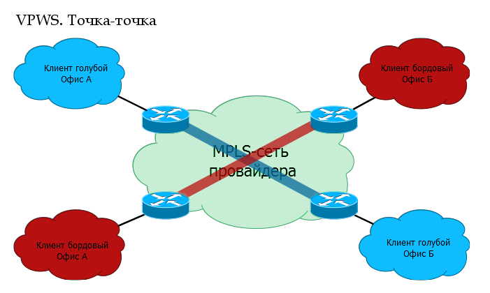
- Point-to-Multipoint . This mode is only for Ethernet, because only in it there is actually such a need. In this case, the client may have three to five to ten to one hundred connection points / branches, and all of them must transfer data to each other, and both to one specific branch and to all at once. This is painfully reminiscent of a regular Ethernet switch , but it would be terrible to talk about it.
Technology Name: VPLS - Virtual Private LAN Service .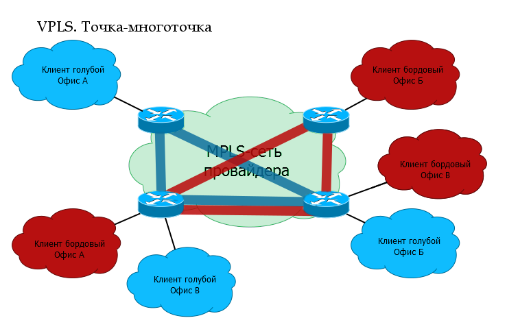
Terminology
Traditionally, terms will be entered as needed. But about some at once.
PE - Provider Edge - provider's MPLS network edge routers to which client devices (CE) are connected.
CE - Customer Edge - customer equipment that directly connects to the provider's routers (PE).
AC - Attached Circuit - PE interface for client connection.
VC - Virtual Circuit is a virtual unidirectional connection through a common network that simulates the original environment for the client. Connects to each other AC-interfaces of different PE. Together they make up a one-piece channel: AC → VC → AC.
PW - PseudoWire - a virtual bidirectional data link between two PEs - consists of a pair of unidirectional VCs. This is the difference between PW and VC.
VPWS. Point to point
VPWS - Virtual Private Wire Service .
At the heart of any MPLS L2VPN solution is the idea of PW - PseudoWire - a virtual cable that is routed from one end of the network to the other. But for VPWS, this PW itself is already a service.
A kind of L2-tunnel through which you can safely pass anything you want.
Well, for example, the client has a 2G base station in Kotelniki, and a controller in Mitino. And this BS can only connect via E1. In ancient times, I would have to stretch this E1 with the help of cable, radio circuits and all kinds of converters.
Today, one common MPLS network can be used for both E1 and L3VPN, the Internet, telephony, television, and so on.
(Someone will say that instead of MPLS for PW, you can use L2TPv3, but who needs it with its scalability and lack of Traffic Engineering?)
VPWS is relatively simple, both in terms of traffic transmission and the work of service protocols.
VPWS Data Plane or user traffic transmission
The tunnel tag is the same as the transport tag, just the long word “transport” did not fit into the heading.
0. A transport LSP is already built between R1 and R6 using the LDP or RSVP TE protocol. That is, R1 is known transport label and output interface to R6.
1. R1 receives from the client CE1 some L2 frame on the AC interface (it may be Ethernet, TDM, ATM, etc. - it does not matter).
2. This interface is tied to a specific client identifier — the VC ID — in a sense, an analog of the VRF in L3VPN. R1 gives the frame a service tag, which remains unchanged until the end of the path. The VPN label is internal to the stack.
3. R1 knows the destination point - the IP address of the remote PE router is R6, finds out the transport label and inserts it into the MPLS label stack. It will be external - transport label.
4. An MPLS packet travels through the operator’s network through P-routers. The transport tag is changed to a new one at each node, the service tag remains unchanged.
5. On the penultimate router, the transport tag is removed — PHP happens. R6 comes with a single VPN service tag.
6. PE2, having received the packet, analyzes the service tag and determines which interface to transfer the unpacked frame to.
If you read the previous release about L3VPN , then you will not see anything new in the issue of the transmission of user traffic - a pair of MPLS tags and transmission over the transport LSP. Ingress PE checks which tags to put and which interface to send, P changes the transport label, and Egress PE takes the VPN label to decide which AC interface to send the received frame to.
VPWS Control Plane or service protocols
The transport label can be assigned as LDP (see the MPLS release ), and RSVP-TE (still waiting in the wings).
For example, take LDP — this protocol is launched across the entire network, which for each Loopback address of each MPLS router will distribute tags over the network.
In our case, R1 after LDP operation will, roughly speaking, know 5 tags: how to get to each of the remaining routers.
We are interested in LSP R1 → R6 and back. Note that in order for the VC to transition to the UP state, both LSPs must be forward and reverse.
There are several different ways to implement a VPWS service. We will talk about this below, and for example we will analyze the one that is most often used now.
For the distribution of service tags is the same LDP, only genetically modified - Targeted LDP . Now he can establish a connection with remote routers and exchange tags with them.
In our example, clients are connected to R1 and R6. R1 through LDP will report its label to this R6 client and vice versa.
At both ends, we manually configure a remote LDP session. It is not tied to the VPN. That is, the same session can be used to exchange tags with any amount of VPN.
A regular LDP is a link-local protocol and looks for neighbors among directly connected routers, that is, the TTL of its packets is 1. However, tLDP has sufficient IP connectivity.
As soon as AC-interfaces with the same VC-ID appear on both sides, the LDP will help them communicate the tags to each other.
What is the difference between tLDP and LDP?
| LDP | tTLDP |
| Only directly connected routers can be neighbors. | A neighbor in the network with which there is IP connectivity can be a neighbor. |
| Search all possible neighbors | Neighbors already defined by configuration. |
| Discovery message broadcast | Address sending a Discovery message to specific neighbors. |
| The FEC is usually the IP address. | VC ID is usually FEC. |
In order not to run far away, immediately practice.
How to build a lab for MPLS L2VPN?
UnetLab + CSR1000V bundle was used as a test bench. Both of these can be obtained absolutely free and legal.
UnetLab OVA .
Cisco CSR1000V IOS-XE .
Instructions for installing UNL and adding images CSR1000V: Tyts.
Accordingly, all the instructions for configuring MPLS L2VPN are given in Cisco IOS-XE notation.
Note: each CSR1000V node requires 2.5 GB of RAM. Otherwise, the image will either not start, or there will be various problems, such as the fact that ports do not rise or losses are observed.
VPWS practice
Simplify the topology to four trunk nodes. By clicking, you can open it in a new tab, to look at it with Alt + Tab, rather than turning the page up and down.
Our task is to run Ethernet from Linkmeup_R1 (port Gi3) to Linkmeup_R4 (port Gi3).
In step 0, IP addressing, IGP routing, and basic MPLS are already configured (see how ).
Initial configuration file.
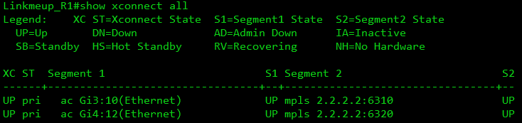
- We configure xconnect at both ends on AC interfaces (PE-CE), note that the VC-ID must be the same.
Linkmeup_R1(config)#interface Gi 3 Linkmeup_R1(config-if)#xconnect 4.4.4.4 127 encapsulation mplsLinkmeup_R4(config)#interface Gi 3 Linkmeup_R4(config-if)#xconnect 1.1.1.1 127 encapsulation mpls
The xconect 4.4.4.4 127 encapsulation mpls command causes the LDP to raise the remote session with the 4.4.4.4 node and creates the MPLS PW with VC ID 127. It is important that the VC ID match on the two opposite AC interfaces - this is a pointer to the fact that they need to be spliced. - Profit
This completes the VPWS configuration.
VPWS configuration file .
Let's follow what was going on behind the scenes of the protocols (the dump was removed from the GE1 Linkmeup_R1 interface). There are major milestones:
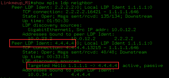
0) IGP converged, LDP identified neighbors, raised the session and distributed transport tags. As you can see, Linkmeup_R4 allocated a transport label 19 for FEC 4.4.4.4.
1) But tLDP has begun its work.
--BUT. First, we configured it to Linkmeup_R1 and tLDP began to periodically send its Hello to the address 4.4.4.4
As you can see, this is a unicast IP packet that is sent from the address of the Loopback interface 1.1.1.1 to the address of the same Loopback of the remote PE - 4.4.4.4.
Packed in UDP and transmitted with one MPLS - transport tag - 19. Pay attention to the priority - the EXP field - 6 is one of the highest, since it is a service protocol packet. We'll talk more about this in the QoS issue.
The PW status is still in DOWN, because there is nothing on the back side.
--B. After setting up xconnect on the Linkmeup_R4 side, immediately Hello and establishing a TCP connection.
At this point, the LDP-neighborhood is established:
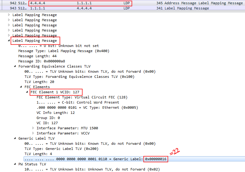
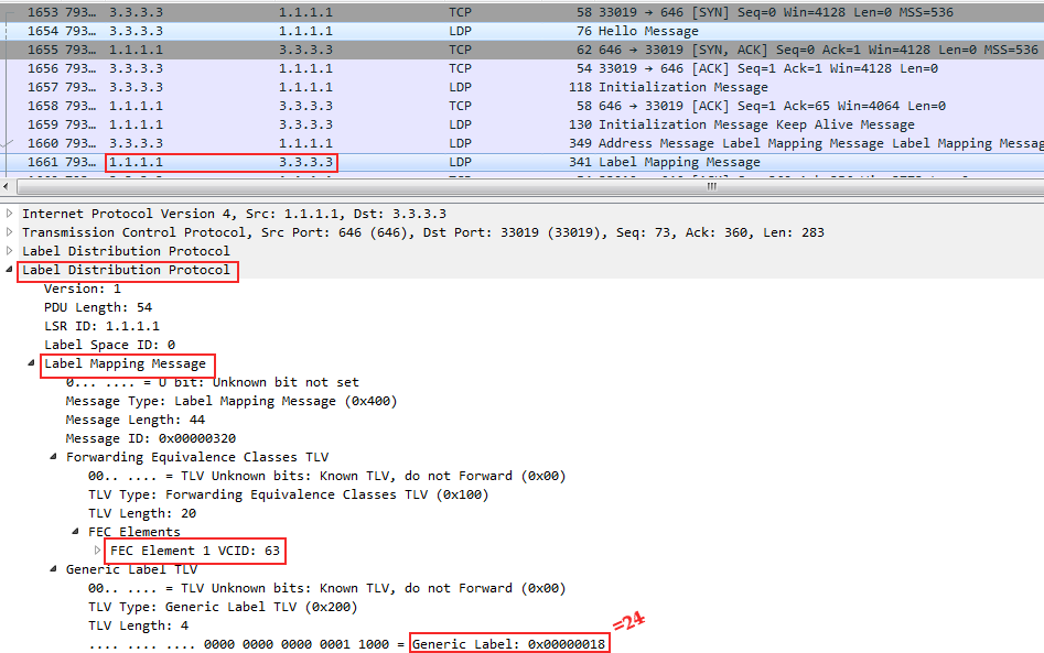
--AT. I went exchange tags:
At the very bottom, you can see that the FEC in the case of VPWS is the VC ID that we specified in the xconnect command — this is our VPN identifier - 127 .
And just below it, the Linkmeup_R4 tag allocated to it is 0x16 or 22 in the decimal system.
That is, with this message Linkmeup_R4 reported Linkmeup_R1, they say, if you want to transfer a frame to a VPN with VCID 127, then use the service tag 22.
Here you can also see a bunch of other Label Mapping messages - this LDP shares everything it has gained - information about all the FECs. It interests us a little, well, and Lilnkmeup_R1 and even more so.
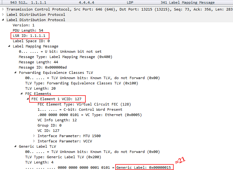
Linkmeup_R1 does the same thing - Linkmeup_R4 informs its label:
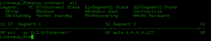
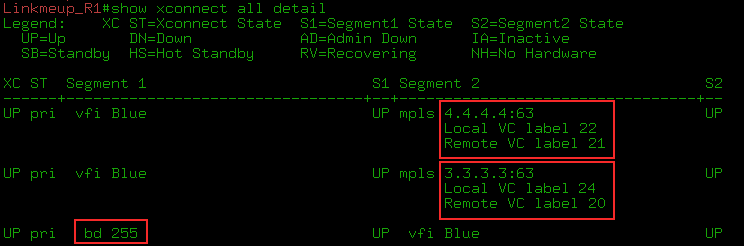
After that, the VCs are raised and we can see the labels and current statuses:
The show mpls l2transport vc detail and show l2vpn atom vc detail commands are generally identical for our examples.
2) Next, the neighbors will only maintain contact:
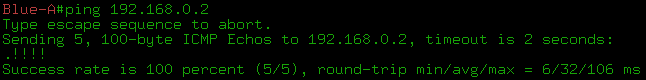
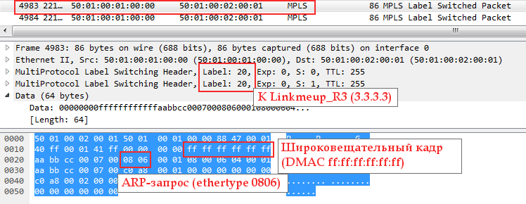
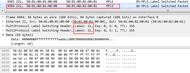
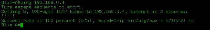
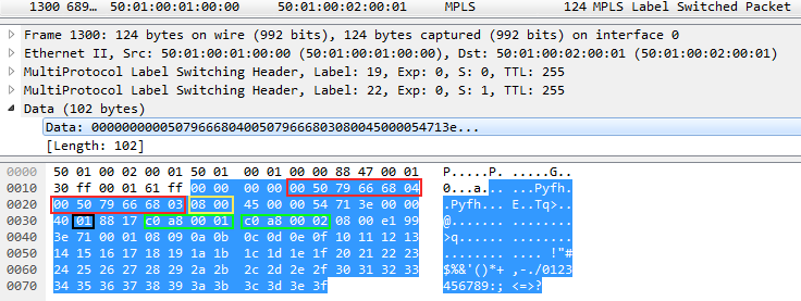
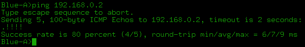
3) Now everything is ready to transfer user data. At this moment we launch ping. Everything is predictable simply: two tags that we have already seen above.
For some reason, Wireshark did not understand the inside of MPLS, but I'll show you how to read the attachment:
The two blocks highlighted in red are the MAC addresses. DMAC and SMAC respectively. The yellow block 0800 — the Ethertype field of the Ethernet header — means within IP.
Next, the black block 01 - the Protocol field of the IP header is the ICMP protocol number. And two green blocks - SIP and DIP, respectively.
Now you can in Wireshark!
Accordingly, ICMP-Reply is returned only with the VPN label, because PHP has taken the place of Linkmeup_R2 and the transport tag has been removed.
If the VPWS is just a wire, then he should calmly transmit a frame with a VLAN tag? Yes, and for this we do not have to reconfigure anything. Here is an example of a frame labeled VLAN:
Here you see the Ethertype 8100 - 802.1q and a VLAN tag of 0x3F, or 63 in the decimal system.
If we transfer the xconnect configuration to the subinterface with the VLAN indication, then it will terminate this VLAN and send a frame without the 802.1q header to the PW.
Types of VPWS
The considered example is EoMPLS (Ethernet over MPLS). It is part of the PWE3 technology, which is the essence of the development of VLL Martini Mode. And all this together is VPWS. The main thing is not to get lost in the definitions. Let me be your guide.
So, VPWS is the common name for point-to-point solutions for L2VPN.
PW is a virtual L2 channel that underlies any L2VPN technology and serves as a tunnel for data transmission.
VLL (Virtual Leased Line) is already a technology that allows you to encapsulate frames of various data link layer protocols in MPLS and transfer them through the provider's network.
There are the following types of VLL:
VLL CCC - Circuit Cross Connect . In this case, there is no VPN label, and the transport is manually assigned (static LSP) on each node, including the swap rules. That is, there will always be only one label per stack, and each such LSP can carry only one VC traffic. I have never met him in my life. Its main advantage is that it can provide connectivity between two nodes connected to the same PE.
VLL TCC - Translational Cross Connect . Same as CCC, but allows using different data link layer protocols from different ends.
It only works with IPv4. PE removes the data link header when received, and inserts a new one into the AC interface.
Interesting? Start from here .
VLL SVC - Static Virtual Circuit . The transport LSP is built using conventional mechanisms (LDP or RSVP-TE), and the VPN service tag is manually assigned. tLDP is not needed in this case. Cannot provide local connectivity (if two nodes are connected to the same PE).
Martini VLL is just about what we dealt with above. The transport LSP is constructed in the usual way, the VPN labels are distributed by the tLDP. Beauty! Does not support local connectivity.
Kompella VLL - Transport LSP in the usual way, for distributing VPN tags - BGP (as it should be with RD / RT). Wow! Supports local connectivity. Well, okay.
PWE3 - Pseudo Wire Emulation Edge to Edge . Strictly speaking, the scope of this technology is wider than just MPLS. However, in the modern world in 100% of cases they work in conjunction. Therefore, PWE3 can be considered as an analogue of Martini VLL with enhanced functionality - LDP + tLDP is also engaged in signaling.
Briefly, its differences from Martini VLL can be represented as follows:
- Reports the status of the PW using the LDP Notification message.
- Supports Multi-Segment PW, when the end-to-end channel consists of several smaller pieces. In this case, the same PW can become segments for several channels.
- Supports TDM interfaces.
- Provides a mechanism for negotiating fragmentation.
- Other ...
Now PWE3 is a de facto standard and it was he who was in the example above.
I’m talking about Ethernet everywhere to show the most obvious example. All that concerns the other channel protocols, it is for self-study, please.
VPLS. Point-to-multipoint
I really like the term point-multipoint. There is something childish in it, playful. And this is what we will talk about now.
VPLS - Virtual Private LAN Service. At its core, it is a switch. The provider connects several customer points to its network at its different ends and provides L2 connectivity. And now it’s the task of the provider’s transport network to take care of correct frame switching, that is, learning MAC addresses.
Terminology
VPLS-domain is an isolated L2 virtual network, that is, roughly speaking, one separate L2VPN. Two different clients - two different VPLS domains.
VSI - Virtual Switching Instance . Virtual switch within one node.
For each client (or service) he has his own. That is, traffic from different VSIs cannot migrate from one to another.
Analog VRF / VPN-instance in L3VPN.
In Cisco terms, this is VFI - Virtual Forwarding Instance . I allow myself to be free to use the terms VPLS-domain, VSI and VFI, sometimes using them as synonyms.
VE - VPLS Edge - PE node, member of the VPLS domain.
VPLS Data Plane
In general terms, the transmission of user traffic looks the same as for the VPWS case, but a step is added to study MAC 's and check the MAC table during traffic transmission.
- A user frame has arrived at the AC port of the PE router.
- The PE router looks at the Ethernet header and checks the MAC address of the sender.
A) If it is already in the MAC table of this VSI, PE immediately proceeds to step 3.
B) If this address is not yet present, it writes the corresponding MAC port to the table and also proceeds to step 3. - The PE router looks at the Ethernet header and checks the destination MAC address.
A) if present in the MAC table of a given VSI:- PE is looking for an output interface for a frame with this MAC. This can be a physical interface or PW.
- If the destination port is a physical interface, it simply sends to that port.
If it is PW, then add the appropriate label - service. This label will be unchanged until the end of the path. - PW is always a channel between two IP nodes, so knowing the IP address of a remote PE, the local PE extracts the transport PE from the label table and puts it on top of the stack — it will change on each P router.
B) If the MAC address is unknown, then as a decent switch, our PE should perform a frame broadcast over all PEs of a given VSI. And he does, scoundrel.- The local PE makes a list of all the remote PEs of this VSI, and, having made copies of this frame, inserts service tags into them - each with its own.
- Next to each copy of the frame is also hung a transport label (also its own for each PE).
- All this bunch of frames sent over the network provider.
- Also copies of the broadcast frame are sent to the AC interfaces, if any, without MPLS headers.
- Remote PE after receiving a frame and unchecking tags (that is, when it has already defined VSI) also acts as a regular switch:
A) If the source MAC address is not yet known, add it to the table. PW for Ingress PE will be specified as the input interface.
B) If the destination MAC address is known to it, it sends the frame to the port behind which it is learned. An already clean Ethernet frame is being sent, without any MPLS headers.
Q) If this MAC could not be found in the table? Broadcast to all the AC ports of this VSI. Note that PE will not send this frame to the PW of this VSI , because all other PEs have already received a copy of this frame from the input PE. This is all the same split-horizon rule (Split Horizon), and so the absence of commutation loops and broadcast storms is achieved. (Oh, if everything was so simple ...)
There is just a hyphae , which shows what is happening. And there is the same hyphae, only with a voice.
As in a conventional switch, the records in the MAC table of the VSI periodically fade and delete.
When it comes to learning MAC addresses in the VPLS, there is one thing that makes it very different from L3VPN. PE should not just know the physical port where the frame came from - it is important to define a neighbor or, more precisely, PW as a virtual interface. The fact is that the client frame needs to be sent not just to some physical port, but to the correct PW, in other words, to the right neighbor.
For this purpose, each neighbor is given a personal tag with which he will send a frame to this PE in this VPLS domain. And later on the VPN tag, looking at the LFIB, PE finds out which neighbor the frame came from.
Let me remind you that L3VPN no matter where the IP packet came from, so the same tag is reported to all neighbors for the prefix in the VRF.
The delivery scheme for user traffic is straightforward. But what about the notorious Control Plane? Again, have to break the brains or small victims?
Sorry, but then begins trash and sodomy. Not immediately - later, but there will be. You act at your own risk.
VPLS Control Plane
From the work of Data Plane, it is already clear that VPLS requires a fully connected PE topology for each VSI. Moreover, not all PE MPLS networks of the provider will be neighbors, but only those with the same VSI.
Therefore, one of the main issues in VPLS is the detection of all PEs where the clients of this VSI are connected. There are two approaches here: manual tuning and automatic detection . The first way was originally proposed by Cisco (Draft Martini), the father of the second is Juniper (Draft Compell).
11 issues SDSM promoted the simplification of the engineer’s life and the automation of everything. And so, that moment came when you need to forget everything that you were taught. This is the first case (if you don’t raise holivar around VTP) when the solution with manual configuration of the neighbors is more popular.
Became interesting?
Before we open the scenes, I want to make a remark: no matter what we get up with VPN tags, transport LSPs are built as usual LDP or RSVP-TE. Therefore, further we will deal with transport only in passing.
Likewise, regardless of the mode used, the VPLS falls apart at a point-to-point PW. That is, we do not have some kind of centralized cloud switching, but simply a set of virtual lines between all neighbors. The frame transfer decision is made by Ingress PE or, more simply, selects the desired PW.
The word "draft", firmly entrenched in these two approaches, has long been illegal and is used by historical inertia. Draft offer can be only six months.
At the moment, the draft-martini has been reborn in RFC 4447 - the Internet standard about PWE3, and the Draft-Compell is outdated and dead.
If we talk specifically about VPLS, then there are two standards:
“Virtual Private LAN Service (VPLS) Using BGP for Auto-discovery and Signaling”. RFC 4761 .
“Virtual Private LAN Service (VPLS) Signaling Protocol Distribution Protocol (LDP) Signaling” RFC 4762 .
Historical background on methods.
VPLS Martini Mode (LDP)
At the beginning of the two thousandth industry strenuously took up the search for solutions for L2VPN across the operator. The criteria were as follows:
- Ease of implementation (obvious requirement)
- On existing hardware (protocols should not require hardware revision)
- Support for existing protocols on the networks of operators.
- The principle of operation of the new mechanism should not be radically different from the existing models.
Luca Martini - a former Cisco employee - provided this unannounced tender with an LDP-based solution.
It will work over the MPLS network.
Label signaling will use LDP, which is already part of MPLS. VPLS Martini Mode is described in RFC4762 standard.
It is this laconic solution that has become the de facto standard in most networks around the world. We already met about how the Martini-mode works in the part about VPWS. Exactly the same here, only remote LDP sessions are created for each VSI, not with one neighbor, but with several.
LDP is used to distribute service tags. Remote sessions with each neighbor in the VPLS domain are configured manually. Since all the participants of this VPLS are known in advance, each of them has an LDP assigned an individual label in the LDP Label Mapping Message.
If a new PE is added to the VPLS domain, you need to configure the LDP neighborhood with all existing PEs of this VPLS. After that, with each of them a new PE will exchange tags.
At all times, the LDP checks the availability of its neighbors. If one of the neighbors leaves the group or becomes unavailable, the session is broken and all the studied MACs in PW to this neighbor are cleared.
If the state of any of the AC ports of the VPLS domain goes to the Down state, or another event occurs that causes the MAC addresses to be cleared from the AC port, then PE notifies all its neighbors by insisting that the MAC addresses be removed in the LDP message MAC Withdraw (Unfortunately, CSR1000V on the test bench does not do this).
There are cases when, in the event of a change in the status of an AC port, PE sends a LDP MAC withdraw message without specifying which MACs it is. This means that each neighbor must clear the entire MAC table of the given VPLS domain.
Now imagine that the bill goes to hundreds, perhaps thousands of records. And across the entire network, all PEs start learning MAC addresses. And what do they do with the frame when they do not find the recipient MAC? Send to all. A short-term broadcast storm occurs without a switching loop.
Without a loop yet. The irony is that such an explosion of Broadcast can clog data transmission channels, especially narrow, for example, RRL. And then the user data will start to get lost. And if the priority traffic queues CS6-CS7, in which the protocol packets are transmitted, are clogged, then the STP can break and ERPS close the ring - and quite a real switching loop is formed with an increasing effect.
If the VPLS domain is not limited to a small part of the network (and usually this is not so) everything can lie down. There is no sadder story in the world than the storm in the VPLS network. Please do not do this.
In the end I will talk about other unpleasant situations that may arise in the VPLS network.
VPLS practice
Let us analyze the work of the VPLS in practice in steps here according to this scheme. This is still the same network, but now the client has decided that two points are not enough for him, he wants four and combine them all into one network.
Clickable
Forgot that we had VPWS service before - this configuration no longer exists. Initial configuration file.
So at step 0 , we have the necessary transport LSPs ready and, accordingly, the routing and so on.
- Create a VFI - Virtual Forwarding Instance
Linkmeup_R1(config)#l2vpn vfi context Blue Linkmeup_R1(config-vfi)#vpn id 63 Linkmeup_R1(config-vfi)#member 3.3.3.3 encapsulation mpls Linkmeup_R1(config-vfi)#member 4.4.4.4 encapsulation mpls
The default mode is LDP signaling. VPN ID - analogue of VCID from the previous example - unique identifier of VPN. It must match on all nodes. The next two teams, we indicate the neighborsthat interfere with sleep,which are also members of this VPLS-domain. Essentially, this is an indication to the LDP to establish a remote session with them, after which it starts sending LDP Hello to the configured neighbors.Similar commands are executed on Linkmeup_R3 and Linkmeup_R4 ...
Linkmeup_R3Linkmeup_R3(config)#l2vpn vfi context Blue Linkmeup_R3(config-vfi)#vpn id 63 Linkmeup_R3(config-vfi)#member 1.1.1.1 encapsulation mpls Linkmeup_R3(config-vfi)#member 3.3.3.3 encapsulation mpls
Linkmeup_R4Linkmeup_R4(config)#l2vpn vfi context Blue Linkmeup_R4(config-vfi)#vpn id 63 Linkmeup_R4(config-vfi)#member 1.1.1.1 encapsulation mpls Linkmeup_R4(config-vfi)#member 4.4.4.4 encapsulation mpls - We create Service Instance on AC interfaces.
Linkmeup_R1(config)#interface gigabitEthernet 3 Linkmeup_R1(config-if)#service instance 10 ethernet Linkmeup_R1(config-if-srv)#description Blue-A Linkmeup_R1(config-if-srv)#encapsulation defaultLinkmeup_R1(config)#interface gigabitEthernet 4 Linkmeup_R1(config-if)#service instance 12 ethernet Linkmeup_R1(config-if-srv)#description Blue-C Linkmeup_R1(config-if-srv)#encapsulation default
In the interface configuration mode, we create a Service Instance - this is the interface binding to the services. How exactly - set up later. The Service Instance number is arbitrary - it is locally significant for the interface (as is the case of the classic subinterface).
encapsulation default means that we grab all the frames indiscriminately (and could choose by the VLAN tag or by the presence of two labels - QinQ, for example), that is, we attach the entire physical interface to the VFI.I want to know more about Service Instance ...
A reasonable question from Occam's razor supporters - why should any service instance - is it not enough just to register a bridge-domain?
The thought is correct, but the service-instance is a “new” approach to the concept of processing tagged traffic and it is called EVC - Ethernet Virtual Circuit.
Here we will switch to Ethernet switches for a moment to understand the origins of this idea.
Traditionally, the VLAN tag has been used both to separate traffic on trunks and to decide on its switching within the device.
802.1q 10, VLAN 10 , . 4094 VLAN ( QinQ).
EVC — 802.1q - , Service instance.
Service-instance — VLAN .
VLAN 10 PW , VLAN 10 VLAN 10 .
10, xconnect . VLAN .
Service Instance VLAN, QinQ CoS. VLAN, , , .
: xconnect bridge-domain.
- ( GE1/1 .1234 ) Service instance .
, EVC, : Cisco . - AC- (service instance) VFI. bridge-domain.
Linkmeup_R1(config)#bridge-domain 255 Linkmeup_R1(config-bdomain)# member vfi Blue Linkmeup_R1(config-bdomain)# member gigabitEthernet 3 service-instance 10 Linkmeup_R1(config-bdomain)# member gigabitEthernet 4 service-instance 12
255 - (0-4096). VLAN, . .
member bridge-domain . VFI, AC- — .Bridge-domain...
Bridge-domain - . brdige-domain , . VLAN, . , , L2- . VPLS.PE...
Linkmeup_R3Linkmeup_R3(config)#interface gigabitEthernet 3 Linkmeup_R3(config-if)#service instance 13 ethernet Linkmeup_R3(config-if-srv)#description Blue-D Linkmeup_R3(config-if-srv)#encapsulation defaultLinkmeup_R3(config)#bridge-domain 255 Linkmeup_R3(config-bdomain)# member vfi Blue Linkmeup_R3(config-bdomain)# member gigabitEthernet 3 service-instance 13
Linkmeup_R4Linkmeup_R4(config)#interface gigabitEthernet 3 Linkmeup_R4(config-if)#service instance 11 ethernet Linkmeup_R4(config-if-srv)#description Blue-B Linkmeup_R4(config-if-srv)#encapsulation defaultLinkmeup_R4(config)#bridge-domain 255 Linkmeup_R4(config-bdomain)# member vfi Blue Linkmeup_R4(config-bdomain)# member gigabitEthernet 3 service-instance 11
VPLS Martini Mode .
VPLS Martini Mode .VPLS Martini Mode. , . l2vpn vfi context Blue l2 vfi Blue . , member neighbor , Bridge-domain bridge-domain, vfi Service instance.
a VPLS Martini Mode .
What happened?
1. LDP . LDP bridge-domain — , AC- ( .).
Linkmeup_R1 Linkmeup_R3:
FEC 63 — VPN. 0x18 ( 24).
, Linkmeup_R3 VFI AC-, Linkmeup_R1, VPN- 24. — 17.
, Linkmeup_R1 — , MAC- .
2. Blue-A, ( Gi1 Linkmeup_R1) ARP-:
Since it is broadcast, after it you can see its exact copy with only one difference - VPN and transport tags:
One frame was sent to Linkmeup_R3, the other - to Linkmeup_R4.
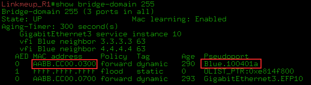
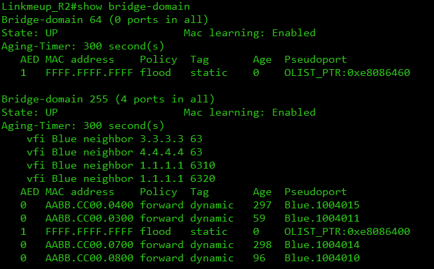
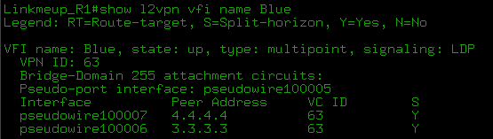
3. In the MAC table we can see the MAC address of the Blue-A node (AABB-CC00-0700) - it is located behind the GE3.EFP10 port (Ethernet Flow Point and Service instance 10 ) - and the MAC corresponding to the IP address 192.168.0.2 (AABB -CC00-0300) - for the Pseudoport Blue.100401a interface .
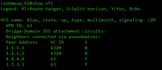
, Pseudoport pseudowire . , PW MAC-? show l2vpn vfi , .
- Pseudoport pseudowire, .
, . — VPLS MAC' PE, Data Plane.
:
- VFI, VPN ID PE .
- AC- Service Instance.
- VFI Service Instance Bridge-domain.
Martini mode:
- VPN LDP ( DU ).
- — - . , .
- . ( — ).
- Martini, , — . .
VPLS Kompella Mode (BGP)
— Juniper. , , MBGP , L3VPN, .
, VPNv4 , VPLS. Route Target . - , Martini Mode.
VPLS Kompella-mode — VPLS Auto-Discovery, Martini. VPLS BGP Signaling.
Control Plane :
—
- Transfer route information and the exchange of tags.
Neighbor Discovery or Auto-Discovery
There was nothing new to invent. The neighbor discovery scheme already used in L3VPN works great here.
Route Target, which is the Extended Community - the main sign of belonging to a particular VSI. Roughly speaking - if the RTs match up - it means in one VSI.
Strictly speaking: If the RT of the received announcement coincides with that configured in VSI, then this VSI wants to know the information from the announcement.
As in L3VPN, you can flexibly organize interaction between different VSIs. But so rarely does anyone do.
Slightly more
VSI RT.
BGP VPLS Address Family: L2VPN AFI (25) VPLS SAFI (65)
PE, - VPLS-. , VSI.
RR, .
BGP L2- PE VSI, BGP Update , , . , L3VPN — vpnv4- PE.
PE BGP Update, RT NLRI , VSI.
, PE VSI. — .
Auto-Discovery.
- , VPLS- , - .
In general, the L2VPN prefix is a rather artificial thing - PE, with its BGP Update, rather, reports the fact of its participation in the VPLS domain and the label of this fact. But it does not play a big role.
Any addresses, especially MAC, in the NLRI field of the message BGP Update VPLS does not transmit. Remember that learning MAC addresses is a complete Data Plane feature .
However, it is still necessary to distinguish between announcements of different VSI, so the familiar Route Distinguisher is also present. Usually it is made automatically from the AS number and VPN ID.
However, what is passed to the NLRI? Only label and RD? Not really:
Formally, the prefix is an RD + node sequence number in the VPLS domain + tag box .
Tag distribution
" — . — "? VPLS Kompella mode . PE — .
, - , — . , , , — .
, .
, :
- VSI RD RT — , L3VPN. CSR1000V , . RD VSI . RT - , VSI . RD RT BGP Update.
- BGP - L2VPN VPLS, PE.
- . , Route-Reflector' , RR ( RR)? - Each VSI PE router allocates a block from the label space. And this is where the interesting begins. The following information is sent to BGP Update from the local PE to the remote:
- RD
- RT
- The sequence number of the node in the VPLS domain.
- MPLS Tag Block
- VE ID
- VE Block Offset
- VE block size
- Label base
Let me remind you that VE - VPLS Edge - the boundary of the network VPLS - PE-router on which VPLS is running.
Before I hit upon all the serious about formulas and values, I consider myself obliged to explain on the fingers in general how it works, because I spent a lot of time and nerves to figure it out.
I sincerely believe that the RFC is a source of unconditional clarity, but sometimes in the same form in which it is the formula for the equivalence of mass and energy for Newton.
When a L2VPN frame arrives at the PE from the MPLS network, you need to know exactly which neighbor it is from — it’s necessary to learn the MAC address, so as in the case of the Martini mode, the basic idea is that each neighbor's PE is in a specific VSI must report a unique tag to see who the frame came from.
Look at this simple picture in more detail:
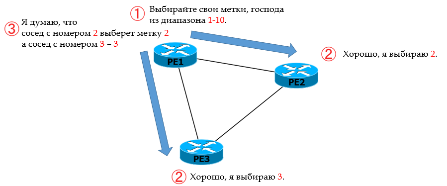
Let R1 be the main one.
0. In Kompella mode, R1 does not explicitly pass the label to its neighbors R2 and R3.
1. Instead, he informs them from which range the labels should be selected to identify the given VC.
2. Each PE has its own sequence number n in the VPLS domain. Knowing yournumber and range of tags, neighbors calculate the outgoing service tag: count n-th in a row from the beginning. That is, R2 took the second (2), and R3 - the third (3).
3. R2 and R3 communicate their R1 numbers, and it also calculates which incoming service tag will be from R2, which is from R3, counting from the beginning of the range 2 and 3.
4. Similarly, R2 and R3 define their own ranges and communicate them to each other and R1. And the cycle of calculations is repeated.
5. In the end, everyone will know the outgoing tags for this VPLS and incoming tags.
Now the second iteration : digging deeper, what kind of matan lies under this simple idea.
The VE ID is manually configured - this is the PE router ID in the VPLS domain (its sequence number). Must be unique within one VSI.
LB - Label Base is the beginning of the range, the first label that can be used.
VBS - VE Block Size is the length of the block of tags - or, more simply, the minimum number of tags in this VSI. For Cisco, the default is 10. For Juniper - 8 (may be reduced to 2 or increased).
This is what the label set will look like: {LB, LB + 1, .., LB + VBS-1}.
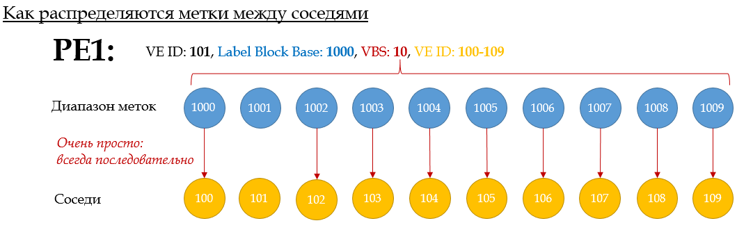
In general, the scheme is simple:
VE ID 100-109 is taken from the balda for example
. This animation shows the process of label distribution on PE1: If PE Xwants to send traffic to PE1, it must use the appropriate X label .
Here's another example for PE5:
Tags are allocated in order — the first of the block — to the neighbor with the lowest VE-ID. The second - the second largest, and so on.
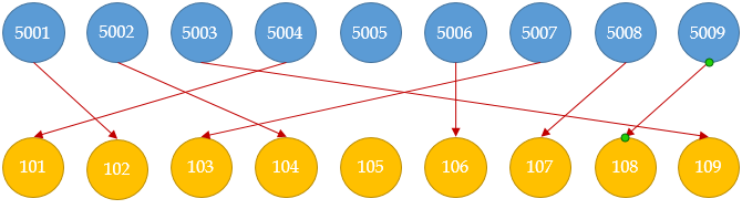
That is, such a situation is impossible :
However, if the allocated number of labels is small, then the VBO - VE Block Offset parameter - the block offset - will help . It allows you to create multiple blocks. And those neighbors who did not have enough, tags are distributed on the same principle, but from a new unit, with a new LB.
The required VBO is calculated using the formula: VBO = WHOLE (VE-ID / VBS) * VBS.
, VBO — , , VE. — , — .
, , {LB, LB+1,… LB+VBS-1}, LB VBO. <LB, VBO, VBS>
: VE ID (VBO+n) (LB+n).
— .
. VBS — 10. VE-ID : PE1 — 101, PE2-102,… PE 10 — 110. PE1 PE5.
1. PE1 Label Base 1000 — 1000-1009 — , .
2. PE1 VBO. VBO=(101/10)*10=100 .
3. PE1 BGP Update : LB: 1000, VBS:10, VBO:100, VE-ID:101 . RD, RT, . PE1 — Update .
4. BGP Update PE1 PE5. VE-ID: 105 . VSI ( RT BGP Update) PE1.
5. , PE5 — , , PE1. VBO. VBO ≤ PE5 VE-ID ≤ VBO+VBS-1. 100≤105≤109. I will explain. PE1 , ID 100-109 ( 100 10) — VE ID .
6. PE5 , (PE1 LB + PE5 VE-ID — VBO) = (1000 + 105 — 100) = 1005 . , , LB , VE-ID VBO. , PE5, L2 VSI PE1 MPLS- VPN- 1005. PE1 , 1005 — , PE5. VE ID.
7. PE5 BGP Update (, 7 — . PE5 BGP Update ).
- but. LB , , 5000 .
- b. VBO = RND(105/10)*10=100 .
- at. BGP Update. LB: 5000, VBS:10, VBO:100, VE-ID: 105 .
- . PE.
8. PE1 VE-ID ( BGP Update), VSI. :
- but. VBO VBS: VBO ≤ PE1 VE-ID ≤ VBO+VBS. 100≤101≤109. Fine.
- b. : (PE1 LB + PE5 VE-ID — VBO) = (1000 + 105 — 100) = 1005 — , PE5 . PE1 VPN 1005, , VPN , MAC, .
9. But that's not all. PE1 should now calculate the outgoing label to PE5. And all the data he has for this.
(PE5 LB + PE1 VE-ID - VBO) = (5000 + 101 - 100) = 5001 . That is, when sending frames to this VSI to PE5, PE1 will insert a 5001 VPN tag into them
. 10. PE5 calculates incoming: (PE5 LB + PE1 VE-ID - VBO) = (5000 + 101 - 100) = 5001 .
This is what I call mutual assistance!
Unfortunately, quite obvious and at the root of my logical mechanism I can only describe in such a complex language.
If you have not yet evolved to understand the mechanism of the Label Block, go back to the video four screens above .
PE10, PE. , 100-109 VE ID 110 . VBO 110=(110/10)*10 . LB 10000 .
PE10 PE5, : 110 ≤ 105 ≤ 119.
.
1. PE5 LB 5030 , VBS PE10 — 10 .
2. PE10,
- . PE5 PE10: (PE10 LB + PE5 VE-ID — PE5 VBO) = 5 — 100) = 10005 . , VBO .
- . PE10: (PE5 New LB + PE10 VE-ID — PE10 VBO) = (5030 + 110 — 110) = 5030 . LB VBO PE10.
3. PE5 PE10 BGP Update, : — , — LB: 5030, VE ID: 105, VBS:10, VBO:110 .
4. VE-ID PE10 110-119,
- . : (PE5 LB + PE10 VE-ID — PE10 VBO) = (5030 + 110 — 110) = 5030 . PE10 VSI PE5 VPN- 5030.
- . PE5: (PE10 LB + PE5 VE-ID — PE5 VBO) = (10000 + 105 — 100) = 10005 . VBO, PE5, PE10.
5. PE , PE10. .
Label Block : Juniper .
. - 10 PE (9 — PE). -, , VE-ID, , . -, VE-ID VE-range! , MPLS !
, , LDP MBGP L3VPN.
, , RFC 4761 ?
Using a distinct BGP Update message to send a demultiplexor to each
remote PE would require the originating PE to send N such messages
for N remote PEs. The solution described in this document allows a
PE to send a single (common) Update message that contains
demultiplexors for all the remote PEs, instead of N individual
messages. Doing this reduces the control plane load both on the
originating PE as well as on the BGP Route Reflectors that may be
involved in distributing this Update to other PEs.
, Control Plane.
, . , , , , . , , CCIE .
- Auto-discovery ( ) L2, MAC-. L3VPN, .
So how does Auto-Discovery work in L3VPN? Some PEs try to tell the whole world about two things - firstly, what prefixes he knows, secondly, to whom they are intended. And he wants to tell everyone about it at once indiscriminately - everyone who is his MBGP neighbors will receive his Update, and RT will see if these announcements are interesting to them. To no - and no trial - will be discarded. And if they are interesting, then the received prefix and its VPN tag will be placed in their VPN routing table.
All the same is true for L2VPN. Except for one: learn MAC addresses . BGP in L3VPN tells everyone the same label — it makes no difference to him where the data packet comes from, his main concern is to transfer it to the correct client interface.
VPLS. , MAC- , . , .
- . BGP Auto-Discovery , .
, -, BGP , Update VPLS-, , .
, «-» (), , «-». -, . when there is no RR, and one PE can send another Update addressable. Then each PE will receive only its message and only its own label. But the reality is that RR has become its (reality) part and, having a neighborhood only with RR, PE sends Update to it, and it sends to all its customers. And if PE sends several Update'ov, then they all scatter on all. It turns out that each of his neighbors will receive not only their own label, but also all the others who have not surrendered to him for nothing.
Just imagine a dump in which you see a hundred Update'ov for left devices.
And here the mechanism of automatic calculation of tags comes to the fore, as a very elegant solution to this problem. It is worth paying tribute to the flexibility of Kiriti Compell’s thought.
And you know, until this concept of a block of tags formed into a consistent set of synapses in my brain, I disregarded it. She seemed clumsy and outdated to me. Something like DVMRP . But now I was inspired by the idea and even somewhat surprised that there is no intelligible explanation anywhere.
I would also note that the situation with the lost labels was somewhat revised with the release of RFC 6624 (in which, by the way, Compella also took direct part)
Label blocks and label values are managed by the PEs. As sites get
added and removed, labels are allocated and released. The easiest
way to manage these is to use fixed-size label blocks rather than
variable-size blocks, although the signaling described here supports
either. If an implementation uses fixed-size blocks, then allocating
a label for a new site may requiring allocating a new block;
similarly, freeing a label may require freeing a block.
If the implementation requires fixed-size blocks, there is probably a
default block size, but the implementation SHOULD allow the
administrator to choose a size. Larger label block sizes mean more
potential «wasted» labels but less signaling overhead, a trade-off
that the administrator might want to control.
, LDP-Signalling + BGP Auto-Discovery . — , .
VPLS Kompella (BGP Signalling)
:
.
.
- VFI, Martini:
Linkmeup_R1(config)#l2vpn vfi context Blue Linkmeup_R1(config-vfi)#vpn id 63 Linkmeup_R1(config-vfi)#autodiscovery bgp signaling bgp Linkmeup_R1(config-vfi-autodiscovery)#ve id 101
VFI: Martini . BGP Autodiscovery + BGP Signalling , BGP Autodiscovery + LDP Signalling . — BGP.
VPLS-. cisco — 10. ve range 11 100 ( ). Huawei — 10, (1-16000). Juniper — 8, (2,4,8, 16...)
Route Distinguisher Route Target — . — VFI.
mpls label range 1000 1999 . . , MPLS (LDP, TE, BGP) ,, - -. .Linkmeup_R1(config)#mpls label range 1000 1999 Label range change will cause 5 labels in the old dynamic range [16-1048575] to go out of range
, . - Service Instance:
Linkmeup_R1(config)#interface gigabitEthernet 3 Linkmeup_R1(config-if)#service instance 10 ethernet Linkmeup_R1(config-if-srv)#description Blue-A Linkmeup_R1(config-if-srv)#encapsulation default Linkmeup_R1(config)#interface gigabitEthernet 4 Linkmeup_R1(config-if)#service instance 12 ethernet Linkmeup_R1(config-if-srv)#description Blue-C Linkmeup_R1(config-if-srv)#encapsulation default - VFI Service Instance.
Linkmeup_R3(config)#bridge-domain 255 Linkmeup_R1(config-bdomain)#member vfi Blue Linkmeup_R1(config-bdomain)#member gigabitEthernet 3 service-instance 10 Linkmeup_R1(config-bdomain)#member gigabitEthernet 4 service-instance 12 - , — BGP.
Linkmeup_R3 Linkmeup_R4.Linkmeup_R1(config)#router bgp 64500 Linkmeup_R1(config-router)#neighbor 3.3.3.3 remote-as 64500 Linkmeup_R1(config-router)#neighbor 3.3.3.3 update-source Loopback 0 Linkmeup_R1(config-router)#neighbor 4.4.4.4 remote-as 64500 Linkmeup_R1(config-router)#neighbor 4.4.4.4 update-source Loopback 0
Address-Family L2VPN VPLS , L2VPN. , VFI Blue, .Linkmeup_R1(config-router)#address-family l2vpn vpls Linkmeup_R1(config-router-af)#neighbor 3.3.3.3 activate Linkmeup_R1(config-router-af)#neighbor 3.3.3.3 send-community extended Linkmeup_R1(config-router-af)#neighbor 3.3.3.3 suppress-signaling-protocol ldp Linkmeup_R1(config-router-af)#neighbor 4.4.4.4 activate Linkmeup_R1(config-router-af)#neighbor 4.4.4.4 send-community extended Linkmeup_R1(config-router-af)#neighbor 4.4.4.4 suppress-signaling-protocol ldp
, Route Reflector' — , Auto-Discovery . PE- MPLS — 100, VPLS- — 20, L2VPN RR — 2, PE RR. , ?
send-community extended — L3VPN Extended Community (RT).
suppress-signaling-protocol ldp — LDP.
BGP VPLS, :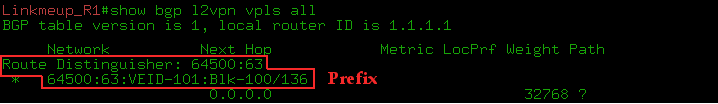
— RD, : AS:VPN ID. — , .
Linkmeup_R3 Linkmeup_R4.PE
Linkmeup_R1Linkmeup_R1(config)#l2vpn vfi context Blue Linkmeup_R1(config-vfi)#vpn id 63 Linkmeup_R1(config-vfi)#autodiscovery bgp signaling bgp Linkmeup_R1(config-vfi-autodiscovery)#ve id 101 Linkmeup_R1(config)#mpls label range 1000 1999 Linkmeup_R1(config)#bridge-domain 255 Linkmeup_R1(config-bdomain)#member vfi Blue Linkmeup_R1(config-bdomain)#member gigabitEthernet 3 service-instance 10 Linkmeup_R1(config-bdomain)#member gigabitEthernet 4 service-instance 12 Linkmeup_R1(config)#interface gigabitEthernet 3 Linkmeup_R1(config-if)# service instance 10 ethernet Linkmeup_R1(config-if-srv)#description Blue-A Linkmeup_R1(config-if-srv)#encapsulation default Linkmeup_R1(config)#interface gigabitEthernet 4 Linkmeup_R1(config-if)# service instance 12 ethernet Linkmeup_R1(config-if-srv)#description Blue-C Linkmeup_R1(config-if-srv)#encapsulation default Linkmeup_R1(config)#router bgp 64500 Linkmeup_R1(config-router)#neighbor 3.3.3.3 remote-as 64500 Linkmeup_R1(config-router)#neighbor 3.3.3.3 update-source Loopback 0 Linkmeup_R1(config-router)#neighbor 4.4.4.4 remote-as 64500 Linkmeup_R1(config-router)#neighbor 4.4.4.4 update-source Loopback 0 Linkmeup_R1(config-router)#address-family l2vpn vpls Linkmeup_R1(config-router-af)#neighbor 3.3.3.3 activate Linkmeup_R1(config-router-af)#neighbor 3.3.3.3 send-community extended Linkmeup_R1(config-router-af)#neighbor 3.3.3.3 suppress-signaling-protocol ldp Linkmeup_R1(config-router-af)#neighbor 4.4.4.4 activate Linkmeup_R1(config-router-af)#neighbor 4.4.4.4 send-community extended Linkmeup_R1(config-router-af)#neighbor 4.4.4.4 suppress-signaling-protocol
Linkmeup_R3Linkmeup_R3(config)#l2vpn vfi context Blue Linkmeup_R3(config-vfi)#vpn id 63 Linkmeup_R3(config-vfi)#autodiscovery bgp signaling bgp Linkmeup_R3(config-vfi-autodiscovery)#ve id 103 Linkmeup_R3(config)#mpls label range 3000 3999 Linkmeup_R3(config)#bridge-domain 255 Linkmeup_R3(config-bdomain)#member vfi Blue Linkmeup_R3(config-bdomain)#member gigabitEthernet 3 service-instance 13 Linkmeup_R3(config)#interface gigabitEthernet 3 Linkmeup_R3(config-if)#service instance 13 ethernet Linkmeup_R3(config-if-srv)#description Blue-D Linkmeup_R3(config-if-srv)#encapsulation default Linkmeup_R3(config)#router bgp 64500 Linkmeup_R3(config-router)#neighbor 1.1.1.1 remote-as 64500 Linkmeup_R3(config-router)#neighbor 1.1.1.1 update-source Loopback 0 Linkmeup_R3(config-router)#neighbor 4.4.4.4 remote-as 64500 Linkmeup_R3(config-router)#neighbor 4.4.4.4 update-source Loopback 0 Linkmeup_R3(config-router)#address-family l2vpn vpls Linkmeup_R3(config-router-af)#neighbor 1.1.1.1 activate Linkmeup_R3(config-router-af)#neighbor 1.1.1.1 send-community extended Linkmeup_R3(config-router-af)#neighbor ppress-signaling-protocol ldp Linkmeup_R3(config-router-af)#neighbor 4.4.4.4 activate Linkmeup_R3(config-router-af)#neighbor 4.4.4.4 send-community extended Linkmeup_R3(config-router-af)#neighbor 4.4.4.4 suppress-signaling-protocol ldp
Linkmeup_R4Linkmeup_R4(config)#l2vpn vfi context Blue Linkmeup_R4(config-vfi)#vpn id 63 Linkmeup_R4(config-vfi)#autodiscovery bgp signaling bgp Linkmeup_R4(config-vfi-autodiscovery)#ve id 104 Linkmeup_R4(config)#mpls label range 4000 4999 Linkmeup_R4(config)#bridge-domain 255 Linkmeup_R4(config-bdomain)#member vfi Blue Linkmeup_R4(config-bdomain)#member gigabitEthernet 3 service-instance 131 Linkmeup_R4(config)#interface gigabitEthernet 3 Linkmeup_R4(config-if)#service instance 11 ethernet Linkmeup_R4(config-if-srv)#description Blue-B Linkmeup_R4(config-if-srv)#encapsulation default Linkmeup_R4(config)#router bgp 64500 Linkmeup_R4(config-router)#neighbor 1.1.1.1 remote-as 64500 Linkmeup_R4(config-router)#neighbor 1.1.1.1 update-source Loopback 0 Linkmeup_R4(config-router)#neighbor 3.3.3.3 remote-as 64500 Linkmeup_R4(config-router)#neighbor 3.3.3.3 update-source Loopback 0 Linkmeup_R4(config-router)#address-family l2vpn vpls Linkmeup_R4(config-router-af)#neighbor 1.1.1.1 activate Linkmeup_R4(config-router-af)#neighbor 1.1.1.1 send-community extended Linkmeup_R4(config-router-af)#neighbor 1.1.1 suppress-signaling-protocol ldp Linkmeup_R4(config-router-af)#neighbor 3.3.3.3 activate Linkmeup_R4(config-router-af)#neighbor 3.3.3.3 send-community extended Linkmeup_R4(config-router-af)#neighbor 3.3.3 suppress-signaling-protocol ldp
mpls label range, .
MPLS Kompella Mode .
VPLS Kompella Mode . , Martini .
What happened?
0. CE
1. BGP Update'.
Update NLRI
Linkmeup_R1 Linkmeup_R3, VPN- , VPLS RT 65400:63. CE-ID ( VE ID)=101, VBO=100, VBS=10, LB=1000.
Linkmeup_R3 Linkmeup_R1: CE-ID=103, VBO=100,VBS=10, LB=3000
Linkmeup_R4 Linkmeup_R1: CE-ID=104, VBO=100,VBS=10, LB=4000
Linkmeup_R1 Linkmeup_R4 , Linkmeup_R3 .
, PE, , ?
Linkmeup_R3→Linkmeup_R1
VBO ≤ Local VE ID ≤ VBO+VBS-1 : 100≤103≤109.
: LB + Local VE ID — VBO = 1000+103-100=1003.
1003 Linkmeup_R3 , Linkmeup_R1 VFI.
Linkmeup_R1→Linkmeup_R3
VBO ≤ Local VE ID ≤ VBO+VBS-1 : 100≤101≤109.
: LB + Local VE ID — VBO = 3000+101-100=3001.
3001 Linkmeup_R1 , Linkmeup_R3 VFI.
Linkmeup_R1→Linkmeup_R4
VBO ≤ Local VE ID ≤ VBO+VBS-1 : 100≤101≤109.
: LB + Local VE ID — VBO = 4000+101-100=4001.
Linkmeup_R4→Linkmeup_R1
VBO ≤ Local VE ID ≤ VBO+VBS-1 : 100≤104≤109.
: LB + Local VE ID — VBO = 1000+104-100=1004.
Linkmeup_R4→Linkmeup_R3 Linkmeup_R3→Linkmeup_R4.
Linkmeup_R4→Linkmeup_R3
VBO ≤ Local VE ID ≤ VBO+VBS-1 : 100≤104≤109.
: LB + Local VE ID — VBO = 3000+104-100=3004.
Linkmeup_R3→Linkmeup_R4
VBO ≤ Local VE ID ≤ VBO+VBS-1 : 100≤103≤109.
: LB + Local VE ID — VBO = 4000+103-100=4003.
2. PE.
, , . , , . , — , , , .
3. , ping Blue-A Blue-D, VPN- 3001 ICMP-Request 1003 ICMP-Reply:
Wireshark - ICMP MPLS
- show mpls l2transport vc detail show l2vpan atom vc detail :
show bgp l2vpn vpls rd X ve-id Y block-offset Z .
:
, Martini, , :
1) . PE VPLS-, ( RR). Martini PE VPLS-.
2) — VE ID. BGP ( RR).
:
- VFI, VPN ID, , VE ID.
- Service Instance AC-.
- VFI Service Instance bridge-domain.
- BGP RR Address-family L2VPN VPLS.
VPLS Kompella mode Juniper: . : cisco .
Matini vs Kompella
, BGP Kompella mode Martini Mode?
- Auto-Discovery. PE LDP- VPLS-. RR .
- Auto-Discovery BGP /. , . , , , BGP, L2VPN BGP . , , .
- BGP Inter-AS VPN. Option C (seamless) MPLS AS PW.
? .
(Inter-AS) VPN Martini VPLS — PE- VPLS-. H-VPLS . .
Auto-Discovery Kompella , :
- , . , , .
. , NMS.
- , RFC 4762 Auto-Discovery Martini. RADIUS BGP.
, cisco LDP + BGP Autodiscovery autodiscovery LDP signaling BGP l2vpn vfi . , ( BGP ).
Martini .
, , Martini Mode , , - . .
VPLS, .
VPLS (H-VPLS)
VPLS — — . Kompella mode RR , Martini Mode — LDP-. O(n^2): n*(n-1)/2 — n — .
— Ethernet — , PE.
- BGP- Route Reflector'?
. — H-VPLS (Hierarchical VPLS), RFC 4762 .
H-VPLS VPLS- : PE-rs MTU-s.
PE-rs — PE — routing and switching . VPLS. , PE. PE-rs: PE-POP , n-PE .
MTU-s — Multi-Tenant Unit — switching . , PE-rs . CE. MTU-s: u-PE , PE-CLE .
MTU-s PE-rs — . . MTU-s PE-rs: MPLS PW QinQ. MPLS, .
PE-rs PE, .
PE-rs MTU-s, PE-rs PW MTU-s AC-, , . :
— , PE-rs MTU-s PE-rs MTU-s,
— , PE-rs PE-rs MTU-s, PE-rs.
, MTU-s ( ) , PE-rs , . PE-rs.
Inter-AS VPN H-VPLS . , ASBR PE-rs .
H-VPLS — :
- Contol Plane.
- Data Plane .
- VPLS- .
! , MAC- PE-rs? , VPLS P, H-VPLS PE, , — MAC-. MTU-s, . .
, , Control Plane Data Plane. , H-VPLS . MAC- , , CPU . H-VPLS .
, , , .
, ?
H-VPLS
Dual-Homing'. , Linkmeup_R1 MTU-s, Linkmeup_R2 — PE-rs.
.
.
H-VPLS Kompella, , Martini.
- — PE-rs. Linkmeup_R2, Linkmeup_R3 Linkmeup_R4 PE-rs — VFI.
Linkmeup_R2(config)#l2vpn vfi context Blue Linkmeup_R2(config-vfi)# vpn id 63 Linkmeup_R2(config-vfi)# member 3.3.3.3 encapsulation mpls Linkmeup_R2(config-vfi)# member 4.4.4.4 encapsulation mpls
Linkmeup_R2 , bridge-domain .Linkmeup_R3 Linkmeup_R4
Linkmeup_R3Linkmeup_R3(config)#l2vpn vfi context Blue Linkmeup_R3(config-vfi)# vpn id 63 Linkmeup_R3(config-vfi)# member 2.2.2.2 encapsulation mpls Linkmeup_R3(config-vfi)# member 4.4.4.4 encapsulation mpls Linkmeup_R3(config-vfi)#bridge-domain 255 Linkmeup_R3(config-bdomain)# member vfi Blue Linkmeup_R3(config-bdomain)# member gigabitEthernet 3 service-instance 13 Linkmeup_R3(config-bdomain)#interface GigabitEthernet3 Linkmeup_R3(config-if)# service instance 13 ethernet Linkmeup_R3(config-if-srv)# description Blue-D Linkmeup_R3(config-if-srv)# encapsulation default
Linkmeup_R4Linkmeup_R4(config)#l2vpn vfi context Blue Linkmeup_R4(config-vfi)# vpn id 63 Linkmeup_R4(config-vfi)# member 2.2.2.2 encapsulation mpls Linkmeup_R4(config-vfi)# member 3.3.3.3 encapsulation mpls Linkmeup_R4(config-vfi)#bridge-domain 255 Linkmeup_R4(config-bdomain)# member vfi Blue Linkmeup_R4(config-bdomain)# member gigabitEthernet 3 service-instance 11 Linkmeup_R4(config-bdomain)#interface GigabitEthernet3 Linkmeup_R4(config-if)# service instance 13 ethernet Linkmeup_R4(config-if-srv)# description Blue-D Linkmeup_R4(config-if-srv)# encapsulation default - Linkmeup_R1 PW Linkmeup_R2.
Linkmeup_R1(config)#l2vpn xconnect context Blue_10 Linkmeup_R1(config-xconnect)# member GigabitEthernet3 service-instance 10 Linkmeup_R1(config-xconnect)# member 2.2.2.2 6310 encapsulation mpls
xconnect, AC- VC-.
ID 6310 , , PE-rs. 63 — VPN ID, 11 — VC MTU-s.
:Linkmeup_R1(config-xconnect)#interface GigabitEthernet3 Linkmeup_R1(config-if)# service instance 10 ethernet Linkmeup_R1(config-if-srv)#encapsulation defaultGi4Linkmeup_R1(config)#l2vpn xconnect context Blue_10 Linkmeup_R1(config-xconnect)# member GigabitEthernet4 service-instance 12 Linkmeup_R1(config-xconnect)# member 2.2.2.2 6320 encapsulation mpls Linkmeup_R1(config-xconnect)#interface GigabitEthernet4 Linkmeup_R1(config-if)# service instance 12 ethernet Linkmeup_R1(config-if-srv)#encapsulation default - PW Linkmeup_R2:
Linkmeup_R2(config)#bridge-domain 255 Linkmeup_R2(config-bdomain)# member vfi Blue Linkmeup_R2(config-bdomain)# member 1.1.1.1 6310 encapsulation mpls Linkmeup_R2(config-bdomain)# member 1.1.1.1 6320 encapsulation mpls
H-VPLS Martini Mode .
H-VPLS
What happened? PW :
VFI Linkmeup_R2 :
MAC' :
H-VPLS , :
- Reservation. Dual-Homing MTU-s PE-rs. .
- H-VPLS QinQ , MPLS PW.
- STP BPDU VPLS.
: H-VPLS PE-rs Redundancy for QinQ Access VPLS Multihoming Juniper tutorial .
L2 c .
- — , .
, . - , MAC- . VPLS-. , , --.
, , QoS, , . , .
- , . . :
, 100 /. .
, - MAC- . VSI, MAC- , . , , 400 /, 400 / , 100 / . MAC-. .
. , . -. , , , , .
, , , - : STP - . — . - , , .
— , . CS6/CS7, . — , , , ? 100 / , .
, .
. . .
, PE PW ( ). — , MPLS-.
, .
, , . , . , , .
— , , VSI.
, . , .
, , PE , PW Down, . , ( ) . ? , PE , VSI. . PE , .
VPLS PE. , DCI . 1 PE — Dual-Homing — Active/Active — . — .
, . . , 1 , .
, . L2. PE1 MAC- — , 1 PE2, MAC-. , -.
, — . , «», , Ethernet — — . — — , .
, , , L2, , , L3VPN. , - . , , .
, . Ethernet, .
— EVPN. , MAC- Control Plane BGP.
useful links
, . : .
- MPLS : .
- AToM': .
- : .
- Juniper , Label Block: .
- VPLS BGP Cisco : .
- : .
- : .
- : .
- H-VPLS: .
- H-VPLS , : .
- H-VPLS Multihoming STP -: .
- — EVPN: .
Luc De Ghein. MPLS Fundamentals 1st Edition . Ina Minei, Julian Lucek. MPLS-Enabled Applications: Emerging Developments and New Technologies 3rd Edition .
, .
, , linkmeup .
Thanks
» , JDima .
» .
» .
» , , .
Source: https://habr.com/ru/post/315028/
All Articles