Random number generator without programming and even computer: how to surprise a young programmer?
Now, when the Arduino continues the triumphal march across the planet, it is unlikely anyone will be surprised by the schemes on the breadboard. White solderless design boards have already become an indispensable element of sets for geeks. Nevertheless, I decided to try to interest young programmers from GoToCamp summer school: to hold for them a master class on the basics of digital circuitry, ending with assembling an interesting device - a random number generator.
When you press a button, a random number is displayed on the indicator. What is the accident, where does it come from? Immediately reveal the secret. The numbers are generated in order: 0, then 1, 2, and so on. The trick is this: a very high frequency of pulses. They are issued so quickly that the numbers merge into one on the indicator. And it is absolutely impossible to guess the number!
Next, you will read about how such a generator is arranged, and how to assemble it yourself.
 I work as a methodologist at the Center for Innovative Educational Technologies (CIOT) at MIPT, and more specifically , I represent the direction of supporting the development of technical creativity. And also participate in the development of products of the company " Cyberphysics " .
')
At the moment, we are actively developing two courses: fundamentals of electronics and programming on the Arduino. For each course we make videos, write guidelines, collect ready-made kits.
The Arduino course is already well developed: a wonderful online course is ready for it, which recently received the EdCrunch OOC Award in the category “Natural and Technical Sciences”.
But the direction of the fundamentals of electronics has great prospects: it is not as well known and popular as the Arduino, which means there is a lot of room for methodical work. At our GoToCamp friendly school, for example, the Arduino has been around for a long time, but nobody has been engaged in the "clean" electronics. I was invited to hold a small master class with senior children. It is worth noting that the guys were already engaged in Arduino by that time, which means it was not worth counting on the wow effect from the flashing LED. Therefore, I thought about the program of the master class, I will write about the result further.

A photo report about the camp itself and my event was published on the website “Entertaining Robotics”, and in this material I would like to reveal a little technical details.
We collected schemes from the Cyber Physics kits that I brought with me:

Here is the scheme of the random number generator, which I proposed to collect (clickable):
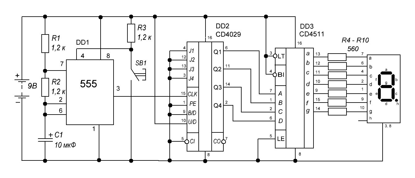
Looks hard? In fact, it is close to the heart of any programmer. After all, it is made of four separate elements - as a program of four functions. Then the components simply fit together: the output of one element is redirected to the input of the next.

Those who like to program in Linux will surely remember the concept of a pipe - such “pipes”, which are indicated by a dash “|” and allow you to quickly create a working script from many small programs (even written in different programming languages). Personally, I simply adore these “pipes” and often use them. Feel like a plumber Mario
Now let's take a closer look at the elements of this scheme.
The most popular timer 555 acts as a pulse generator. At the output, the timer produces a series of pulses that will “push” the counter and make it add value.
The internal device of the timer chip is not very easy to explain to a beginner. But on the other hand, this chip is very convenient to use as programmers like - in the “black box” mode. Conclusions of the timer 555:
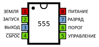
In this figure, the power pins are marked in red, the inputs are green, and the outputs are blue. I liked this way of displaying the chipset pinout, I took it from the English-language Wikipedia.
And this is how this chip is used in our particular scheme. Nothing complicated - absolutely standard way, according to a typical scheme.
 The timer mode is set by three elements: resistors R1 and R2 and capacitor C1.

Simply substituting values into this formula (or using an online calculator , if lazy to count), we get a frequency of 40 Hz - that is, 40 oscillations per second. Accordingly, the period will be 25 milliseconds, and the human eye will never notice such a frequent change of the number on the indicator.
The fourth conclusion is responsible for the reset and works in the inverse mode: for the reset to occur, you need to close it to the "minus". Therefore, through a pull-up resistor, it is connected to the “plus” of the power, and through a button with a “minus”. As long as we hold the reset button, the timer stands still and does not give out anything - at this time you can admire the number on the indicator.
A counter is a very simple thing, almost like a variable i in programming. The counter accumulates in itself a number, that's all. And the increment of the counter occurs on an external impulse. You can do it by pressing a button, but you can, as in our case, from a timer.
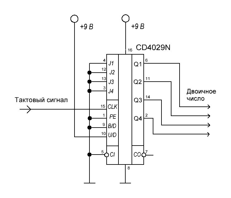
The counter chip is arranged as follows:

In our scheme, the meter is also connected quite simply:
If we again draw an analogy with programming, then a decoder is like a library function that associates a binary number with a set of luminous segments on an object of the type “standard seven-segment indicator”. There are some geeks who prescribe all this themselves through a microcontroller - I saw examples on both the Arduino and the “pure” ATMega. Do not do this! There is a special convenient microcircuit for this!

Here the most important are the inputs for the binary number (A, B, C, D) and the outputs (“a” ... “f”), which are directly connected to the corresponding segments, which are also labeled with letters. Service Inputs:
Everything is quite simple here. A seven-segment indicator with a common cathode is used. Each of the LEDs is connected via a current limiting resistor. It happens that some try to save on resistors and connect the seven-segment through only one resistor - in this case there is a special picture in the documentation for the indicator:
 On the left - “connecting a healthy person.” Each LED is through its own resistor. On the right is a “smoker connection”, only one resistor at all. Failure to comply with this rule leads to the fact that some LEDs take more current than others, and because of this, the segments glow unevenly.
That's all! Now, for those who want to assemble such a scheme themselves:

And the list of components to it:
Scheme assembled (clickable photo):

Many may ask: why do we need an “iron” random number generator at all? Isn't it easier to take a microcontroller, program it ... After all, the random number generator is a ready-made solution that has long been known to all!
Then I remembered the story of how I, in a group of comrades, participated in the technical equipment of the field role-playing game "Aliens under the ground" (of course, based on the famous film). An important element of the game was the lanterns, which should have been “knock up” some time after switching on and off for a while - to create a terrible and hopeless atmosphere. For small flashlights, a tiny board with a microcontroller, so small that a standard random number generator library along with the program did not fit into it, was divorced! There was no time to optimize, in no case was it possible to replace the microcontroller either.
As a result, I began to seriously look in the direction of an alternative option - to take the value from the freely “hanging” input of the microcontroller, from the ADC. I even tested it, and I remember that the result was not completely random (some values were systematically met more often than others), but it was quite suitable for the needs of the game. It’s funny that creating a pseudo-random number from the depths of a microcontroller turned out to be more difficult in a purely mathematical way than taking uncertainty directly from the outside world ...
Pro hardware random number generators have a good Wikipedia article.
The master class I conducted at GoToCamp showed that high school students can quite easily compile and understand such a scheme if they explain in detail all the steps and give a preliminary “load” in the form of 10 more simple entry level schemes.

The guys got an important experience of combining several simple schemes into one complex. We have combined a pulse generator, a counter, a decoder and a seven-segment indicator into a scheme - a random number generator. Notice how easy this happened because of the clear interfaces between the small circuits. The first scheme - a pulse generator - has a square wave at the output, that is, a square wave. The frequency of this meander sets the speed of the counter. The counter, in turn, "talks" with the decoder in the language of binary code. And that, in turn, transmits data in a form already convenient for the seven-segment indicator.

In the photo - testing of generators for randomness using a stopwatch on the phone :)
The simplicity and consistency of this scheme due to the fact that the chips in it are chosen so that they are most easily joined to each other. Hence the conclusion for the future for both engineers and programmers: try to be well aware of the interaction of the components with each other and select them so that they “communicate” in the language that is as simple and understandable as possible.
And most importantly - learn ready-made solutions and successful practices! Much has been invented before us. Learn the alphabet of digital electronics, even if you are already a confident arduinschik or hardcore microcontroller. You never know why these or other cases can be useful.
 The scheme is borrowed from Tronix Book 2 of the remarkable American circuitry popularizer Gary Gibson. And no less remarkable graduate of MIPT, engineer, microprocessor developer Yuri Panchul told us about this book, for which he thanks a lot!
The author is Tatyana Volkova , a specialist in educational and methodical work at CIET MIPT (direction of supporting the development of technical creativity), developer of Cyber Physics products .
When you press a button, a random number is displayed on the indicator. What is the accident, where does it come from? Immediately reveal the secret. The numbers are generated in order: 0, then 1, 2, and so on. The trick is this: a very high frequency of pulses. They are issued so quickly that the numbers merge into one on the indicator. And it is absolutely impossible to guess the number!
Next, you will read about how such a generator is arranged, and how to assemble it yourself.
Prehistory
I work as a methodologist at the Center for Innovative Educational Technologies (CIOT) at MIPT, and more specifically , I represent the direction of supporting the development of technical creativity. And also participate in the development of products of the company " Cyberphysics " .')
At the moment, we are actively developing two courses: fundamentals of electronics and programming on the Arduino. For each course we make videos, write guidelines, collect ready-made kits.
The Arduino course is already well developed: a wonderful online course is ready for it, which recently received the EdCrunch OOC Award in the category “Natural and Technical Sciences”.
But the direction of the fundamentals of electronics has great prospects: it is not as well known and popular as the Arduino, which means there is a lot of room for methodical work. At our GoToCamp friendly school, for example, the Arduino has been around for a long time, but nobody has been engaged in the "clean" electronics. I was invited to hold a small master class with senior children. It is worth noting that the guys were already engaged in Arduino by that time, which means it was not worth counting on the wow effect from the flashing LED. Therefore, I thought about the program of the master class, I will write about the result further.
A photo report about the camp itself and my event was published on the website “Entertaining Robotics”, and in this material I would like to reveal a little technical details.
We collected schemes from the Cyber Physics kits that I brought with me:
How does the "iron" random number generator
Here is the scheme of the random number generator, which I proposed to collect (clickable):
Looks hard? In fact, it is close to the heart of any programmer. After all, it is made of four separate elements - as a program of four functions. Then the components simply fit together: the output of one element is redirected to the input of the next.
Those who like to program in Linux will surely remember the concept of a pipe - such “pipes”, which are indicated by a dash “|” and allow you to quickly create a working script from many small programs (even written in different programming languages). Personally, I simply adore these “pipes” and often use them. Feel like a plumber Mario
Now let's take a closer look at the elements of this scheme.
Pulse generator
The most popular timer 555 acts as a pulse generator. At the output, the timer produces a series of pulses that will “push” the counter and make it add value.
The internal device of the timer chip is not very easy to explain to a beginner. But on the other hand, this chip is very convenient to use as programmers like - in the “black box” mode. Conclusions of the timer 555:
In this figure, the power pins are marked in red, the inputs are green, and the outputs are blue. I liked this way of displaying the chipset pinout, I took it from the English-language Wikipedia.
And this is how this chip is used in our particular scheme. Nothing complicated - absolutely standard way, according to a typical scheme.
Simply substituting values into this formula (or using an online calculator , if lazy to count), we get a frequency of 40 Hz - that is, 40 oscillations per second. Accordingly, the period will be 25 milliseconds, and the human eye will never notice such a frequent change of the number on the indicator.
The fourth conclusion is responsible for the reset and works in the inverse mode: for the reset to occur, you need to close it to the "minus". Therefore, through a pull-up resistor, it is connected to the “plus” of the power, and through a button with a “minus”. As long as we hold the reset button, the timer stands still and does not give out anything - at this time you can admire the number on the indicator.
Counter
A counter is a very simple thing, almost like a variable i in programming. The counter accumulates in itself a number, that's all. And the increment of the counter occurs on an external impulse. You can do it by pressing a button, but you can, as in our case, from a timer.
The counter chip is arranged as follows:
- The digit is displayed as a binary number at the outputs Q1 ... Q4
- On a signal at the 15th pin (“Clock signal”), the counter adds one
- In decimal mode, after the digit 9, the counter is reset and starts again from 0
In our scheme, the meter is also connected quite simply:
- The U / D input (counting direction) is connected to the “plus” of the power supply so that the score goes upwards.
- PE (preset resolution), J1 ... J4 (data inputs for preset counter), B / D (binary counting mode), CI and CO (transfer input and output) are all connected to ground as their functionality in this circuit we do not need
Decoder
If we again draw an analogy with programming, then a decoder is like a library function that associates a binary number with a set of luminous segments on an object of the type “standard seven-segment indicator”. There are some geeks who prescribe all this themselves through a microcontroller - I saw examples on both the Arduino and the “pure” ATMega. Do not do this! There is a special convenient microcircuit for this!
Here the most important are the inputs for the binary number (A, B, C, D) and the outputs (“a” ... “f”), which are directly connected to the corresponding segments, which are also labeled with letters.
- the input for testing the indicator (LT) and for its extinguishing (Bl) is set to “plus”
- input for "freezing" the numbers (LE) - to "minus".
Seven-segment indicator
Everything is quite simple here. A seven-segment indicator with a common cathode is used.
Wiring diagram of the random number generator
That's all! Now, for those who want to assemble such a scheme themselves:
And the list of components to it:
- NE555 Timer Chip
- Chip Counter CD 4029
- CD 4511 Decoder Chip
- Clock Button
- Seven-segment indicator with a common cathode (for example, Kingbright SC56-11SRWA)
- Electrolytic capacitor 10 microfarad, operating voltage not less than 25 V
- 1.2 kΩ resistor: 3 pcs.
- 560 ohm resistor: 7 pcs
- Jumpers
- Solderless Breadboard
- Battery (in our case, 9 volts, but the circuit also works in a wider range - from 5 to 12 volts, you only need to adjust the values of the resistors)
- Battery Connector
Scheme assembled (clickable photo):
Why do you need it?
Many may ask: why do we need an “iron” random number generator at all? Isn't it easier to take a microcontroller, program it ... After all, the random number generator is a ready-made solution that has long been known to all!
Then I remembered the story of how I, in a group of comrades, participated in the technical equipment of the field role-playing game "Aliens under the ground" (of course, based on the famous film). An important element of the game was the lanterns, which should have been “knock up” some time after switching on and off for a while - to create a terrible and hopeless atmosphere. For small flashlights, a tiny board with a microcontroller, so small that a standard random number generator library along with the program did not fit into it, was divorced! There was no time to optimize, in no case was it possible to replace the microcontroller either.
As a result, I began to seriously look in the direction of an alternative option - to take the value from the freely “hanging” input of the microcontroller, from the ADC. I even tested it, and I remember that the result was not completely random (some values were systematically met more often than others), but it was quite suitable for the needs of the game. It’s funny that creating a pseudo-random number from the depths of a microcontroller turned out to be more difficult in a purely mathematical way than taking uncertainty directly from the outside world ...
Pro hardware random number generators have a good Wikipedia article.
Results
The master class I conducted at GoToCamp showed that high school students can quite easily compile and understand such a scheme if they explain in detail all the steps and give a preliminary “load” in the form of 10 more simple entry level schemes.
The guys got an important experience of combining several simple schemes into one complex. We have combined a pulse generator, a counter, a decoder and a seven-segment indicator into a scheme - a random number generator. Notice how easy this happened because of the clear interfaces between the small circuits. The first scheme - a pulse generator - has a square wave at the output, that is, a square wave. The frequency of this meander sets the speed of the counter. The counter, in turn, "talks" with the decoder in the language of binary code. And that, in turn, transmits data in a form already convenient for the seven-segment indicator.
In the photo - testing of generators for randomness using a stopwatch on the phone :)
The simplicity and consistency of this scheme due to the fact that the chips in it are chosen so that they are most easily joined to each other. Hence the conclusion for the future for both engineers and programmers: try to be well aware of the interaction of the components with each other and select them so that they “communicate” in the language that is as simple and understandable as possible.
And most importantly - learn ready-made solutions and successful practices! Much has been invented before us. Learn the alphabet of digital electronics, even if you are already a confident arduinschik or hardcore microcontroller. You never know why these or other cases can be useful.
The scheme is borrowed from Tronix Book 2 of the remarkable American circuitry popularizer Gary Gibson. And no less remarkable graduate of MIPT, engineer, microprocessor developer Yuri Panchul told us about this book, for which he thanks a lot! The author is Tatyana Volkova , a specialist in educational and methodical work at CIET MIPT (direction of supporting the development of technical creativity), developer of Cyber Physics products .
Source: https://habr.com/ru/post/314446/
All Articles