LED Management Tutorial with the Robotics Development Kit
This tutorial demonstrates how to manage GPIO contacts with a simple example, similar to writing the simplest “Hello World” program: by setting the UP card so that you can blink with an external LED.

The Intel RealSense Robotics Development Kit (RDK) consists of an Intel RealSense R200 depth camera and an Aaeon * UP card. The UP board in this system is the computing core. For connecting external devices, this board is equipped with a 40-pin I / O terminal shown in the figure above. A total of 28 independent GPIO pins are placed on the I / O terminal on the UP board. The Ubuntu 14.04 kernel platform drivers have been developed for the UP card, providing for the numbering of GPIO contacts in Linux in the range from 0 to 27 with emulation of the capabilities of the Raspberry Pi board.
Access to GPIO hardware in this tutorial will be at a low level using Linux sysfs. With Sysfs, Linux users (or code in user space) can interact with devices at the system (kernel) level.
')
For this tutorial, no special libraries are needed because the sysfs interface is used.
Important! Note that the Linux GPIO numbers in Figure 1 differs from both physical contact numbers and wiring on the UP board . Linux GPIO numbers are assigned according to the Raspberry Pi BCM GPIO numbering scheme.
For comparison with the layout on the Raspberry Pi board, visit the site .
It is enough to configure the UP board as part of the RDK according to the Quick Start Guide From Zero to Hero: Getting up and running with the Intel RealSense Robotic Development Kit , and everything is ready to work on the first real project. We will control the switching on of the LED using the C programming language and GPIO pins on the UP board.
You will assemble the simplest circuitry and connect it to the GPIO pins of the UP card.
Before writing the code, you should familiarize yourself with the numbering of contacts on the UP board and assemble a simple electrical circuit. To begin with, we simply turn on the LED using the 3.3 V contact and the ground contact on the UP board. The circuit of our electric circuit is as follows:

Before you start, turn off the UP board. If you work with it in the on state, there is a risk of a short circuit, and this should be avoided, especially if you consider that this is our first project.
Check again how everything is connected. When everything is ready, the electrical circuit should look like this:

Turn on the UP board. The LED should light up immediately.
So, the simplest electrical circuit has been tested, now it’s time to switch the positive wire from the permanently connected 3.3 V contact to one of the programmable GPIO contacts. Here is how the scheme will look like:

When everything is ready, the electrical circuit should look like this:

The following source code example will make the LED blink.
If the source file is called blink.c, you can compile the code with the following command:
In this tutorial for working with the UP board, a simple circuit diagram is created; the UP board and the C program using the Linux sysfs mechanism control the operation of the LED, which should flash 10 times.
In the next tutorial in this series, we will adjust the LED brightness using depth data from the R200 camera and Intel RealSense cross-platform API, for which we will have to re-work both the electrical capture and the C program.
UP fee in Robotics Development Kit
The Intel RealSense Robotics Development Kit (RDK) consists of an Intel RealSense R200 depth camera and an Aaeon * UP card. The UP board in this system is the computing core. For connecting external devices, this board is equipped with a 40-pin I / O terminal shown in the figure above. A total of 28 independent GPIO pins are placed on the I / O terminal on the UP board. The Ubuntu 14.04 kernel platform drivers have been developed for the UP card, providing for the numbering of GPIO contacts in Linux in the range from 0 to 27 with emulation of the capabilities of the Raspberry Pi board.
Access to GPIO hardware in this tutorial will be at a low level using Linux sysfs. With Sysfs, Linux users (or code in user space) can interact with devices at the system (kernel) level.
')
For this tutorial, no special libraries are needed because the sysfs interface is used.
Important! Note that the Linux GPIO numbers in Figure 1 differs from both physical contact numbers and wiring on the UP board . Linux GPIO numbers are assigned according to the Raspberry Pi BCM GPIO numbering scheme.
For comparison with the layout on the Raspberry Pi board, visit the site .
How to light up the LED using the UP board
It is enough to configure the UP board as part of the RDK according to the Quick Start Guide From Zero to Hero: Getting up and running with the Intel RealSense Robotic Development Kit , and everything is ready to work on the first real project. We will control the switching on of the LED using the C programming language and GPIO pins on the UP board.
What do you learn
You will assemble the simplest circuitry and connect it to the GPIO pins of the UP card.
What is needed
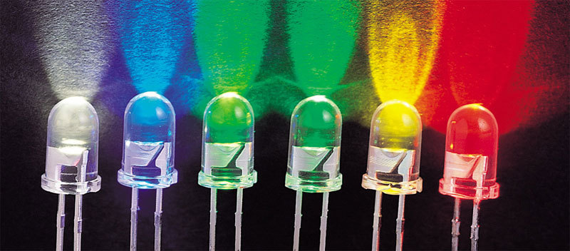
- 1 small LED of any color.
- 1 50 ohm resistor.
- Single core wire of small cross section.
- Dummy or crocodile clips (or both) for fixing the contacts.
Let there be light!
Before writing the code, you should familiarize yourself with the numbering of contacts on the UP board and assemble a simple electrical circuit. To begin with, we simply turn on the LED using the 3.3 V contact and the ground contact on the UP board. The circuit of our electric circuit is as follows:
Before you start, turn off the UP board. If you work with it in the on state, there is a risk of a short circuit, and this should be avoided, especially if you consider that this is our first project.
- Based on the available parts, assemble the electrical circuit either on the circuit board or using crocodile clips.
- Pin 1 (+3.3 V) must be connected to the long leg of the LED (anode). This contact supplies a voltage of 3.3 V. In contrast to the GPIO contacts on the UP board, this contact is not programmable: it is impossible to control it using software.
- Connect the short leg of the LED to the resistor. Then connect the second resistor pin to pin 6 (ground) on the UP board.
Check again how everything is connected. When everything is ready, the electrical circuit should look like this:
Turn on the UP board. The LED should light up immediately.
LED control using software code
So, the simplest electrical circuit has been tested, now it’s time to switch the positive wire from the permanently connected 3.3 V contact to one of the programmable GPIO contacts. Here is how the scheme will look like:
- Turn off the UP card again before changing anything in the connections.
- Transfer the positive wire from pin 1 to pin 7.
When everything is ready, the electrical circuit should look like this:
Source code to control blinking
The following source code example will make the LED blink.
Source
#include <sys/stat.h> #include <sys/types.h> #include <fcntl.h> #include <stdio.h> #include <stdlib.h> #include <unistd.h> #define IN 0 #define OUT 1 #define LOW 0 #define HIGH 1 #define PIN 24 /* physical pin 18 */ #define POUT 4 /* physical pin 7 */ static int GPIOExport(int pin); static int GPIOUnexport(int pin); static int GPIODirection(int pin, int dir); static int GPIORead(int pin); static int GPIOWrite(int pin, int value); int main(int argc, char *argv[]) { int repeat = 9; /* * Enable GPIO pins */ if (-1 == GPIOExport(POUT) || -1 == GPIOExport(PIN)) return(1); /* * Set GPIO directions */ if (-1 == GPIODirection(POUT, OUT) || -1 == GPIODirection(PIN, IN)) return(2); do { /* * Write GPIO value */ if (-1 == GPIOWrite(POUT, repeat % 2)) return(3); /* * Read GPIO value */ printf("I'm reading %d in GPIO %d\n", GPIORead(PIN), PIN); usleep(500 * 1000); } while (repeat--); /* * Disable GPIO pins */ if (-1 == GPIOUnexport(POUT) || -1 == GPIOUnexport(PIN)) return(4); return(0); } Int GPIOExport(int pin) { #define BUFFER_MAX 3 char buffer[BUFFER_MAX]; ssize_t bytes_written; int fd; fd = open("/sys/class/gpio/export", O_WRONLY); if (-1 == fd) { fprintf(stderr, "Failed to open export for writing!\n"); return(-1); } bytes_written = snprintf(buffer, BUFFER_MAX, "%d", pin); write(fd, buffer, bytes_written); close(fd); return(0); } Int GPIOUnexport(int pin) { char buffer[BUFFER_MAX]; ssize_t bytes_written; int fd; fd = open("/sys/class/gpio/unexport", O_WRONLY); if (-1 == fd) { fprintf(stderr, "Failed to open unexport for writing!\n"); return(-1); } bytes_written = snprintf(buffer, BUFFER_MAX, "%d", pin); write(fd, buffer, bytes_written); close(fd); return(0); } Int GPIODirection(int pin, int dir) { static const char s_directions_str[] = "in\0out"; #define DIRECTION_MAX 35 char path[DIRECTION_MAX]; int fd; snprintf(path, DIRECTION_MAX, "/sys/class/gpio/gpio%d/direction", pin); fd = open(path, O_WRONLY); if (-1 == fd) { fprintf(stderr, "Failed to open gpio direction for writing!\n"); return(-1); } if (-1 == write(fd, &s_directions_str[IN == dir ? 0 : 3], IN == dir ? 2 : 3)) { fprintf(stderr, "Failed to set direction!\n"); return(-1); } close(fd); return(0); } Int GPIORead(int pin) { #define VALUE_MAX 30 char path[VALUE_MAX]; char value_str[3]; int fd; snprintf(path, VALUE_MAX, "/sys/class/gpio/gpio%d/value", pin); fd = open(path, O_RDONLY); if (-1 == fd) { fprintf(stderr, "Failed to open gpio value for reading!\n"); return(-1); } if (-1 == read(fd, value_str, 3)) { fprintf(stderr, "Failed to read value!\n"); return(-1); } close(fd); return(atoi(value_str)); } Int GPIOWrite(int pin, int value) { static const char s_values_str[] = "01"; char path[VALUE_MAX]; int fd; snprintf(path, VALUE_MAX, "/sys/class/gpio/gpio%d/value", pin); fd = open(path, O_WRONLY); if (-1 == fd) { fprintf(stderr, "Failed to open gpio value for writing!\n"); return(-1); } if (1 != write(fd, &s_values_str[LOW == value ? 0 : 1], 1)) { fprintf(stderr, "Failed to write value!\n"); return(-1); } close(fd); return(0); } If the source file is called blink.c, you can compile the code with the following command:
gcc –Wall –o blink blink.c Conclusion
In this tutorial for working with the UP board, a simple circuit diagram is created; the UP board and the C program using the Linux sysfs mechanism control the operation of the LED, which should flash 10 times.
In the next tutorial in this series, we will adjust the LED brightness using depth data from the R200 camera and Intel RealSense cross-platform API, for which we will have to re-work both the electrical capture and the C program.
Source: https://habr.com/ru/post/313942/
All Articles