As we Wednesday Arduino on 8051, or OS on one process

In the summer of 2016, we released our new board for the development of Z-Wave devices - Z-Uno. This is an absolutely innovative device, which has no analogues in the world of Z-Wave yet. Given the large number of programmer chips, I decided to share some of the solutions used in Z-Uno.
In short, we made a simplified cooperative OS on 1 process on an 8051 microcontroller with an API like Arduino.
Let's answer the main question right away: WHY ?
')
As I already wrote , Z-Wave devices are made very difficult. Requires not only skills with microcontrollers, but also special software and programmers.
Our goal was to give the user a relatively simple means to create Z-Wave devices without using expensive and specific utilities and hardware. In addition, the Z-Wave protocol is not too obvious, and we wanted to “hide under the hood” all the details of the protocol, leaving the user only the main point.
Since we wanted to give the user the maximum amount of hardware capabilities of the Z-Wave chip (legs, tire hardware drivers, ...), it was decided to take the Arduino environment as a basis. It is popular, it just gives the opportunity to work with the hardware of the microcontroller and uses a slightly simplified C ++ (not all the pluses for pluses are available there). And not only the style of the API (a list of generally accepted functions for accessing hardware in Arduino), but also IDE. But we have a nuance - a lot of work needs to be done for the user, especially the radio exchange, i.e. you need to periodically take control and do all the “black work”, returning control when we are not busy with radio service and processing commands.
In addition, we cannot distribute the Z-Wave libraries as is (the protocol owner's requirement associated with the NDA), and even though the network is full of firmware in the .bin or .hex format (for OTA-update devices, for example), include libraries on wednesday arduino we couldn't. Given all this, we just needed to isolate the user code from the Z-Wave packet processing code.
So, we made the OS on 1 process, giving the user-developer a simple API in the style of Arduino.
About the use of Z-Uno (albeit the old version) I wrote in a separate article . There are also several other articles on GT. Here will also be described the details of the implementation of the internals Z-Uno. Dear reader, welcome to us behind the scenes.
Architecture
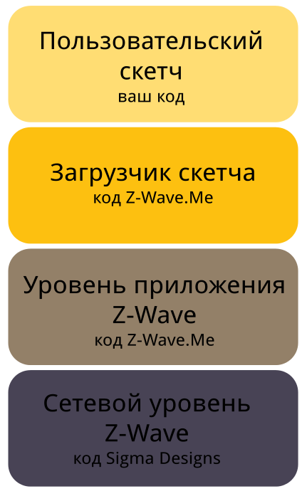 In short, Z-Uno consists of 4 parts:
- Bootloader (bootloader), allowing to change our firmware. Almost all devices with OTA-update have this.
- The Z-Wave stack from Sigma Designs is a library linked to the next level.
- Implementation of Z-Wave command classes, basic functions, as well as all work with the sketch (fill the sketch and the response side of the Arduino-like API). This part we will call the “sketch loader”.
- Custom sketch, downloaded by the user independently through the Arduino IDE - just like from any of the Arduino boards.
"Multitasking"
The transfer of control from the sketch to the sketch loader occurs voluntarily. However, a long stay in the sketch (more than 10 ms) can spoil the exchange of data on the radio. In the opposite direction (from the sketch loader to the sketch), control is also transferred when the sketch loader is idle. At the same time, even transferring control to the sketch, many interrupts occasionally return control to the sketch loader for a while. Such is the simple cooperative OS.
Entry points to the user process (sketch)
In the classic C interface, the program starts with main (). Arduino sketches use setup () and loop () instead. We decided to adapt the same convention - when starting Z-Uno during the initialization of iron, setup () is called, then all the time that the Z-Wave stack and the sketch loader are not busy, loop () is called. Everything seems simple. There are also hit points in the user sketch related to the implementation of interaction over the Z-Wave network: getter and setter. About them - below.
Presentation in Z-Wave and Channels
Z-Uno has a lot of legs, iron can be connected differently. But this is not just Arduino, we have Z-Wave here for some reason. The main task of Z-Uno is to display the periphery connected to the legs of Z-Uno on the Z-Wave entity and vice versa. Since Z-Wave devices can have many different functions, we decided to give the user access to several entities at once. For simplicity, we decided to create an entity on the channel (I will not go into the details of Z-Wave, there were other ways to do this). Each channel has its own type depending on the user's settings, and the appropriate Command Classes are implemented inside. We have four such types so far: a binary sensor (class of Sensor Binary commands), a multilevel sensor (Sensor Multilevel), a relay (Switch Binary) and a dimmer (Switch Multilevel). In the future, there will be more counters (Meter) and locks (Door Lock).
All these classes implement the get current values (Get) commands, the relays and dimmers also implement the Set value. Receiving commands and sending reports is done by our code - the sketch loader, but these values need to be taken from the user sketch and given to it. We implemented this interaction through the getter / setter mechanism. When describing each channel, the user must specify the functions to use as getter and setter.
Getter and setter
For correct work in the Z-Wave network, we need to promptly respond to requests for current states and process new value commands on request from other devices on the network. For example, a motion sensor could send us a Set command to turn on a relay implemented on Z-Uno. Or the controller could ask us about the current status of this relay or the current value of the sensor connected to Z-Uno. We need to promptly execute all these commands, and we should get the value from the user code, and transmit the new values for the channels to the same place. “Operationally” is a loose concept. We thought it was enough to wait for the user code to exit loop () or call delay (). Thus, getter and setter are started only when user code is not executed.
Now let's sort the blocks of the resulting system in order.
Building and loading code in Z-Uno
Since we decided to use the Arduino IDE, we needed to create our own compiler package, loader, libraries, and header files, which is installed through the Arduino IDE Board Manager. Here we described the installation process for those who are not familiar with it.
Compiler
The Z-Wave chip is based on the 8051 architecture, i.e. Standard avr-gcc does not suit us. We found nothing interesting and at the same time open for 8051 except the SDCC compiler sdcc.sourceforge.net . Alas, he understands pure C, no “pluses”. But with the compilation of the C-code, it does quite well, although not as well as the expensive Keil (which is used to create all Z-Wave devices, including our part of the Z-Uno code). We were lucky, the creators of SDCC had already foreseen many options that we used: restrictions on the use of Code Space, IDATA, XDATA, addresses of interrupt vectors ... More on this later in the resource sharing section.
C ++ support
Most libraries for Arduino somehow use C ++, or rather some of its syntactic constructions. As already mentioned, C ++ SDCC cannot compile. But many Arduino libraries use classes, heritage, and polymorphism. We tried different options, starting with the good old cfront and ending with the modern clang. After much deliberation, it was decided to take the clang and use it to parse the user code, followed by the creation of the purest C-code, which will already be collected by the SDCC. Thus, we use clang as a translator of C ++ code in C, and not as a full-fledged compiler. By the same principle, the first C ++ compiler worked - the previously mentioned cfront.
Here the question immediately arises: "Why did you go in such an archaic and strange way?" The answer is extremely simple: the creation of a full-fledged C ++ compiler for 8051 would take a lot of time, I can even say sooo much time, incommensurable more than the time we spent on the whole Z-Uno project. In addition, we immediately tried to limit the supported semantic constructions, all sorts of “features” of C ++, and that is why we called our translator uCxx (abbreviated u = [mj: u] = micro). Strictly speaking, our translator supports a very limited dialect of the C ++ language. uCxx currently does not know how to overload operators, does not know anything about templates, also does not work with links, does not support multiple inheritance, he has never heard of the new and delete operators. His whole gentleman's collection is limited to class-level polymorphism and virtual functions, but this set is quite enough to port most of the Arduino libraries with almost full preservation of their interface. In addition, uCxx makes some "chips" that only he has. For example, especially for Z-Uno, he is able to rebuild work with the pin ports of a dedicated port in such a way as to ensure the maximum speed of pin control, he can fill in necessary sections of code with the buttons (NOP instruction), etc. We immediately went away from universality and tried to make a special and as quick as possible solution for development.
There are many technical details about code generation.
Now briefly try to describe the principles of operation of uCxx. First of all, what does it consist of!? We use a specially patched version of libclang (so far there are still a lot of minor flaws, such as determining the type of binary / unary operator and similar things - that’s what the library needed to fix a little), libclang binding (it also had to be edited to match the patched library) for Python. The main development language of uCxx, therefore, is precisely Python. Python was also chosen to simplify development and gain time. Yes, uCxx is just a Python script pulling libclang, but nevertheless, the uCxx Python code is converted to a binary build using the pyinstaller package and the end user does not need to know anything about Python, its execution environment, and additional libraries.
Let's try to show how uCxx works. First, the user sketch goes through the analysis phase, on which all used hiders are defined and a list of additional kernel files / libraries is generated by them that must be included in the compilation (the native Arduino preprocessor works in the same way). After this, the .ino file is sent to the preprocessor: a third-party sdcpp is used (part of the SDCC compiler). After that, the received cpp-file is pushed into the clang, which at the output already gives Abstract Syntax Tree (AST) of the entire file. It is at this stage that all syntax errors are detected. How the main part of the AST tree for the source code looks like can be seen in special debugging files that have the suffix _ast.txt. The received AST-tree is analyzed by the code uCxx. In fact, this is a bypass of a large tree. For each class found, a special structure is created that stores all the data of the class object. For each method, its new name is determined, which is formed on the basis of the name of the parent class, the number and type of input parameters. Such a technique is generally accepted for C ++ compilers and is called “mangling”. UCxx uses its own algorithm for constructing such names, since The clang algorithm built into the library turned out to be inoperative for designers and it was much more difficult to fix it than to write your own. Each non-static class method is also added - the first parameter, which is further dereference as this, which is also the standard approach for OOP compilers. For example, in languages such as Python, this syntax is familiar to the user.
The central part of our translator is the implementation of virtual methods. In uxx, they are implemented using a virtual method table, which is generated statically for each class at the compilation stage. The table is filled with pointers to functions. A function, in this case, we call a class method translated into C. For the names of these functions, a special order relation is introduced. Thus, the parent class always contains the beginning of the table, and the descendant class only expands the existing table if it has new virtual methods, and fills the beginning of the table for all the overloaded methods of the parent class. When a virtual function is called, the method of the root parent class is always called, which already transitions to the desired function of the descendant using the virtual functions table. A pointer to a virtual function table is always stored inside the object data (a special field of the class structure). You can see in more detail how this happens directly in the code - the output files of the translator - the files with the suffix "_ucxx.cpp".
One of the features of uCxx is the generation of initialization functions for each module. Such functions are used to initialize global objects, populate virtual function tables. Calls of all functions of initialization of the modules included in the sketch are added to the setup () function of the user sketch.
Compilation of the entire set of files needed to build a sketch is carried out twice. On the first pass, the set of user-defined methods available for calling and the set of initialization methods are determined; on the second pass, the “refined code” is generated based on these sets, from which all unused methods of user classes are excluded. This approach reduces the output sketch size and does not greatly increase the compilation time.
At the final stage, sdcc is called for all received “purebred” C-files, and it collects the final hex-version of the sketch. That's it - the sketch is ready for upload inside Z-Uno
Loader
Naturally, AVR-DUDE does not suit us either. Moreover, we change only the user part of the code, saving our firmware to Z-Uno. Therefore, we use the more or less standard Serial API protocol for Z-Wave, similar to that used for USB-sticks. It allows you to transfer a sketch to Z-Uno (to the auxiliary EEPROM memory), initiate the Code Space (FLASH) overwriting and reboot (this is done by the sketch loader).
To communicate using this protocol with our firmware, we wrote our own small utility in Python. It is also called to fill the sketch, as well as new versions of our firmware (sketch loader).
Libraries and Headers
For the correct assembly of user code, we need libraries and header files to describe the available functions. This is where the Arduino-like API is described. All this part lies on Github , you can feel and edit it.
Libraries are often adaptations of standard Arduino libraries for the specifics and architecture of Z-Uno. Some users have already begun to help us by offering pull requests on github with their libraries or our fixes.
OS calls and various ABI
I’ll emphasize right away that the Z-Uno firmware (the Z-Wave stack and the sketch loader) are assembled by the Keil compiler, while the sketch is assembled in SDCC. To say that the code is incompatible is to say nothing. These compilers use radically different ABI (Application Binary Interface), i.e. notation for passing parameters (through which registers, in what order, how to pass a pointer to the memory, ...) And then we crossed the hedgehog with a snake. To go from one code to another, we used the idea of system calls in Unix-like operating systems. A “stack” was allocated in memory (in fact, just a small sequence of bytes). Both codes know the exact address of this array. The user code first puts the “syscall number”, then in the specified order the parameters corresponding to this syscall are put into this array (via zunoPush ), after which it jumps to the specified bootloader code (LCALL). The point where the jump goes is rigidly set when compiling a custom sketch. Once in the sketch bootloader code, looking at the syscall number, the parameters are already taken (via zunoPop) and the necessary operation is performed on them. In the opposite direction, everything works in a similar way. Transferring parameters through this “array stack” allows you to ignore which registers a particular compiler uses (in our case, Keil C51 and SDCC can use different sets of registers).
To make it easier to imagine how differently these two compilers understand the transfer of parameters in a function, we give a small example. So Keil always passes the first one-byte parameter through the R7 register, and the two-byte parameter through the R6-R7 registers (see here ), while the SDCC will transmit the same parameter through the DPL in the case of a single-byte parameter, and in DPL / DPH two-byte (see the SDCC manual , p. 53, item “3.12.1 Global Registers used for Parameter Passing”). Thus, there is a complete incompatibility of these compilers when passing parameters of functions through registers.
Since both codes (sketch / sketch loader) are compiled separately and they don’t know anything about each other, they may well assume that nobody spoils the registers. Therefore, we save all registers when moving from one code to another and restore it when we return.
What syscall do we have? Well, of course, pinMode, digital / analogRead / Write, delay implementations (see below), work with Serial0 / 1, SPI, read / write EEPROM and NZRAM (XRAM area that lives even in a dream), setting KeyScanner, working with IR - driver, going to sleep, sending reports and commands to other devices (see ZUNO_FUNC ).
Stack
First, we tried an idea with different stacks and when moving from Z-Wave to user space and vice versa. They did it by allocating two stacks in IDATA and saving the SP during the transition. However, this approach was not very economical, because for large nesting of functions (and in C ++ there are a lot of attachments) we often overwhelmed the user stack. In general, the 8051 stack is very limited compared to the AVR.
As a result, we returned to the obvious version of the total stack. But there is one nuance. About him below (about delay).
Memory sharing
In addition to the stack, there are other common resources. For example, memory. In 8051 there are two of them: IRAM and XRAM. Operations with IRAM are shorter and faster (MOV), with XRAM longer (MOVX). Work with pointers is possible only in XRAM.
In both cases, we just gouged out Keil's memory so that he would not use it, and on the contrary, only it was allowed in SDCC. Such is the simple division of resources. Only areas for passing parameters to syscall and the stack area in IRAM are shared (well, of course, all the registers are also in IRAM, they are also shared).
Implementation of delay ()
Most functions require doing something and returning control quickly enough. But such a simple function as delay () required a lot of effort. The fact is that we cannot just block the chip by doing something like while (counter--); as is done in the Arduino. If this is done, the radio transmission for this time will be interrupted (radio interrupts will work, but not byte analysis). And with a delay of more than 10 ms, the radio exchange will simply become impossible due to packet loss.
We have solved this task quite cunningly: with delays of less than 10 ms, we go into a cycle in which we start the library function of working with incoming radio packets. She is responsible for building the packet and transferring the incoming queue to the temporary buffer. In addition, it implements relaying and other functions of the Z-Wave network layer. But for a long time it is impossible to do this: radio control will not work, answers to requests for sensor values will not be sent either.
Therefore, in case of delays for a longer time, we still have to exit the user code and return to the sketch loader code, which is responsible for high-level packet processing and responses to them. In this case, we remember that we are in the delay, jump into the sketch loader, work as standard, but do not start loop (). As soon as the timer has hit, and we need to return, we remove the flag and do RET to go back from delay () to the user code.
I note that all getter and setter still work even while waiting in delay ().
Working with tires
 The Z-Wave chip has a lot of hardware drivers: PWM, ADC, UART, SPI, ... Of course, we wanted to give the
 Those tires for which there are no hardware drivers (I2C, 1-Wire, specific to DHT-11), we implemented directly in the user code based on GPIO (in libraries connected to the sketch).
Work with pins, fast pins mode
However, protocols such as I2C may require high speed. Reaching 400 kHz, causing syscall just will not work. Too much "eats" this level of abstraction. Therefore, another solution was found. We selected one port (8 pins) from the rest and called it “quick pins”. A new data type s_pin was added, which at the clang level (before compilation) was transformed into a constant, and the digitalWrite and digitalRead functions with such pins are immediately converted into a record in the pin control registers. For example, to enable P0.5:
P05 |= (1 << 5); In addition, indirect addressing with such pins was added - when passing a variable myPin of type s_pin to the function in which digitalWrite or digitalRead stands with this variable, the latter are converted into direct work with the register. For example, P0 |= (1 << (myPin-9) I note that in the 8051 architecture it is impossible to address any pin indirectly, but only within a specific port. That is why we chose one “fast” port P0 (legs 9-16 per Z -Uno). So instead of 1 ms to work with the port via syscall, we came to 2 µs for indirect and 0.5 µs for direct addressing of fast pins.What is hidden from the user
Let me remind you that our task was to hide part of the functions from the user, both because of NDA and for simplification. As a result, the entire kitchen associated with Z-Wave is completely hidden - the user does not worry about the multitude of command classes needed to comply with the Z-Wave Plus standard. For example, Associations, firmware updates, setting the wake-up time, battery charge report, communication range test, encryption, working with channels, device version reports and command classes — this and much more has been implemented correctly. The user needs to write the logic of the device itself - the connection of pins with user-defined channel types. For example, when receiving on / off commands on the first channel, turn on / off the pin, and when receiving on / off commands on the second channel, send a command via UART to another microcontroller.
In addition, the implementation of the radio part, packet processing, etc., which is related to the Z-Wave standard, and that it makes no sense to give to the user, is completely hidden under the hood.
Conclusion
In general, we managed to solve quite nicely the task of creating our own Z-Wave devices for people who do not know the details of the protocol or the subtleties of this microcontroller. Simple knowledge of the Arduino is enough. For the first quarter since the release of Z-Uno, we managed not only to sell the planned batch, but also to build a good community around this project. In addition, we regularly publish new and new examples of using Z-Uno with various sensors.
By the way, while working on the project, we had two competitors, but both curled up right before our launch. It seems that the task was really not easy ...
I hope our experience will be useful, and in the comments the readers will advise us something clever.

Source: https://habr.com/ru/post/313898/
All Articles