The minimum Hello Word limit on AVR is 0 bits.
2 years ago I saw the entry "The limit of the minimum Hello Word on AVR is 2 bytes" on Habrahabr ` s user swap_map with subtitle at the end:
Then I thought that it was simply impossible, but now I could do it.

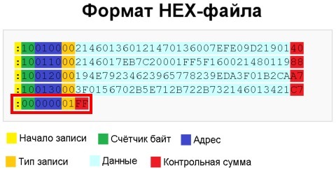
Probably, it should be said that my way of writing such a firmware is somewhat non-standard, because in fact there is no firmware, there is only a form for creating an empty * .hex file. The contents of * .hex read from empty (after the chip erase operation of the atmega328p microcontroller looks like this:: 00000001FF . Let me use the image from the swap_map article for visual comparison. I redrawn around the code that is necessary for my example of the minimum Hello word.
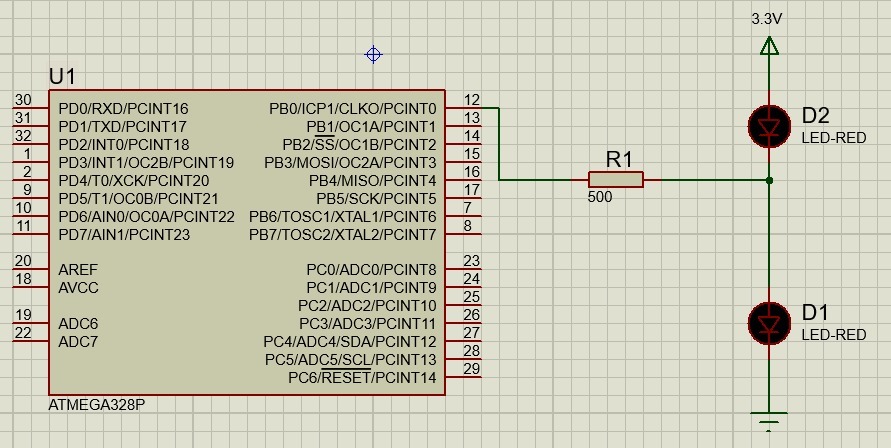
I will light the LED on port 0 of port b and only it. The flicker frequency will be equal to 16 kHz, in order to make sure that the leg still jerks, assembled the following scheme. Attention: The voltage at the anode of the LED of the upper arm must be less than the total Forward Voltage parameter for these LEDs, otherwise they are closed by the power bus and, for sure, will burn or degrade greatly. In my case, the voltage at the anode was 3.2V.
')
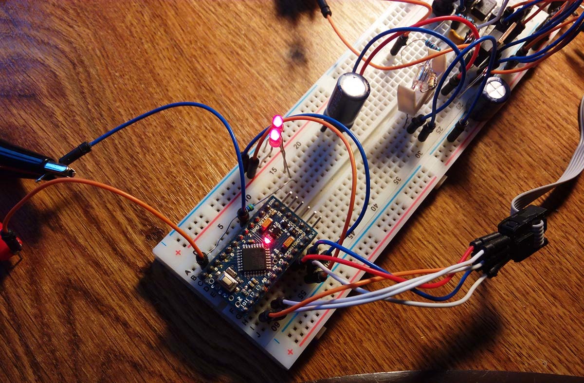
This circuit in the original version (with an empty firmware) does not work in a proteus, the proteus complains of an incorrect opcode. Do not worry, I will collect in the gland. The crocodiles on the oscillographic probes are on the left, the USB ASP programmer cable is on the right, from the capacitor and further along the breadboard - another project.
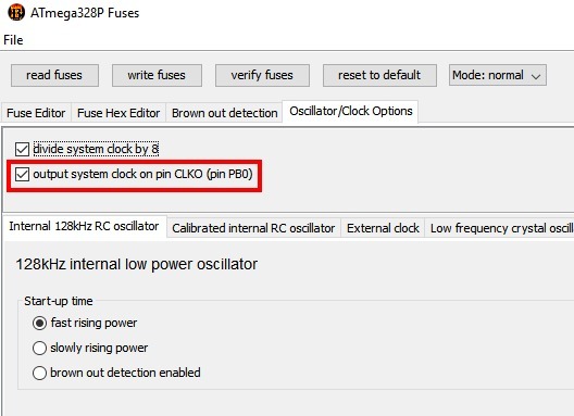
How does it blink? And it blinks through the setting FUSE bits. In ATMega328p and in some other avr MKs there is a bit called CKOUT, when set, which outputs the clock frequency to pin 0 of port b. At the same time, the clock source is not important at all: internal RC chains, external quartz or even an incoming clock signal - all this will go to the port. As a clock source, I chose an internal RC circuit with a frequency of 128 kHz with a divider of 8. Therefore, the total frequency will be 16 kHz. As a result, fuses are set like this: hf = DB, lf = 13, ef = 07. The red frame is circled in the same bit.
So what, it works? Yes, you can see on the photo of the breadboard above that both LEDs are lit, but somehow this is not very clear. Let's connect my old man c1-49 and see the state of pin 0 of port b:

A period of 60 µs gives us a frequency slightly more than 16 kHz, but the period in the photo does not reach 60, the frequency goes out more, I’ll write it down to a good age and a very long time calibration. We can assume that the result has been achieved.
I hope this entry will make some people at least a quick scan of the configuration options used by the MK using FUSE bits.
And now it's my turn to say: “Who will write the LED blinking program shorter?”
Anyone write an LED blinking program even shorter?
Then I thought that it was simply impossible, but now I could do it.
Probably, it should be said that my way of writing such a firmware is somewhat non-standard, because in fact there is no firmware, there is only a form for creating an empty * .hex file. The contents of * .hex read from empty (after the chip erase operation of the atmega328p microcontroller looks like this:: 00000001FF . Let me use the image from the swap_map article for visual comparison. I redrawn around the code that is necessary for my example of the minimum Hello word.
I will light the LED on port 0 of port b and only it. The flicker frequency will be equal to 16 kHz, in order to make sure that the leg still jerks, assembled the following scheme. Attention: The voltage at the anode of the LED of the upper arm must be less than the total Forward Voltage parameter for these LEDs, otherwise they are closed by the power bus and, for sure, will burn or degrade greatly. In my case, the voltage at the anode was 3.2V.
')
This circuit in the original version (with an empty firmware) does not work in a proteus, the proteus complains of an incorrect opcode. Do not worry, I will collect in the gland. The crocodiles on the oscillographic probes are on the left, the USB ASP programmer cable is on the right, from the capacitor and further along the breadboard - another project.
How does it blink? And it blinks through the setting FUSE bits. In ATMega328p and in some other avr MKs there is a bit called CKOUT, when set, which outputs the clock frequency to pin 0 of port b. At the same time, the clock source is not important at all: internal RC chains, external quartz or even an incoming clock signal - all this will go to the port. As a clock source, I chose an internal RC circuit with a frequency of 128 kHz with a divider of 8. Therefore, the total frequency will be 16 kHz. As a result, fuses are set like this: hf = DB, lf = 13, ef = 07. The red frame is circled in the same bit.
So what, it works? Yes, you can see on the photo of the breadboard above that both LEDs are lit, but somehow this is not very clear. Let's connect my old man c1-49 and see the state of pin 0 of port b:
A period of 60 µs gives us a frequency slightly more than 16 kHz, but the period in the photo does not reach 60, the frequency goes out more, I’ll write it down to a good age and a very long time calibration. We can assume that the result has been achieved.
I hope this entry will make some people at least a quick scan of the configuration options used by the MK using FUSE bits.
And now it's my turn to say: “Who will write the LED blinking program shorter?”
Source: https://habr.com/ru/post/313786/
All Articles