2D magic in detail. Part Three Global coverage
Global illumination, dynamic light and decals (yes, there is such a word :)) in action.
I love to look at white objects without texture. Recently, in an art store, I have long considered plaster figures, which artists use as model objects. It is very nice to see all these smooth transitions of light and soft shadows. Later, when I returned home and opened Unity3D, it came to be understood that the light in my project is still dull and unrealistic.
From that moment on, the story of global coverage began, which I will tell today.
Previous articles
Part one. Shine.
Part two. Structure.
Part Three Global coverage.
Table of contents
- How to do procedurally generated effects
- What is global coverage?
- Direct lighting
- Indirect lighting
- Wall lighting
- Decals
- Improvements to dynamic lighting
- Conclusion
How to do procedurally generated effects
The very first comment on the initial article of this cycle was: “Magic! And straight arms.” I’m not sure about the complete integrity of my hands (at the end of the previous article there are visual bugs that confirm this), but there is no magic here. I will share the secret of procedural effects:
At least a third of the work has already been done, as soon as you had the idea to make procedurally generated content. It can be anything: spots on the wings of butterflies or the atmosphere of the planet, trees and bushes, etc. Sometimes, especially with light, it is immediately clear how the "generation" occurs in the real world. Most often, the algorithm boils down to: "send infinitely many rays in an infinite number of directions and get a realistic picture."
And this is the second third - to write a similar algorithm (taking into account the fact that infinity is well approximated by a thousand). It turns out simple, like "hello world", but slow. Hands immediately stretch something to optimize, but, believe me, you should not. It is better to start it in the editor and go to drink tea. And after tea to understand that the invented method will not give a beautiful picture and redo everything. If you plan to preassign once a picture in the editor, and then use it in the build, you can stop there.
- And finally, the last third is to come up with an algorithm that will give a visually close result, but it will work faster. Usually, knowledge of all interesting containers, algorithms, trees, etc. comes in handy. For one of these algorithms - thank you very much Dionis_mgn , who once told you how to make cool two-dimensional shadows.

Planet from the previous project.
For example, the sky for the planets in one of the projects was predicted as follows: for each pixel of the sky 20-30 rays were emitted to different parts of the Sun, it was considered how many rays intersect with the planet itself, what part of the path the ray passed in the atmosphere (for similarity of Rayleigh dispersion). With good quality, calculations for one planet lasted about 30–40 seconds and produced various atmospheres at the exit depending on the distance of the Sun, the “composition” and density of the atmosphere. And this algorithm managed quite good sunsets.

Sunset on Earth II.

The whole star system.
What is global coverage?
I noticed the need to do something with lighting when I added day and night to the demo. Rays of light from the sun and the moon beautifully illuminated the walls of the castles, but something strange was happening inside the rooms: as soon as the dawn rays touched the tops of the towers, it became light in the deepest casemates, forgive the pun like during the day. Of course, the reason is not in the light source “defaultSun”: when changing day and night, the color and brightness of the sky changed. So they influenced every pixel, regardless of whether it was a blade of grass on the old roof or a stone in a gloomy cave.
Let's define what picture we want to get. “It’s light in the light and dark in the dark” sounds good for a starting point. As in the real world: it is dark in the closet, lighter in the corridor, lighter in the room, and quite bright on the roof. Let us reformulate: the elements of the background, characters and other objects should receive as much light as the photons could get to them from the celestial sphere (in our 2D case, the celestial circle). It is clear that it is better to direct our "photons" not from the sky, as in the real world, but on the contrary, from an illuminated point to the sky: otherwise, we will need too many shots, and even that, many will go "to milk".
One of the conditions: we expect global illumination only for static objects: walls, earth. So we will be able to run it at boot and use the results of the entire level (without affecting fps).

A slice of the scene. In fact, the calculations go for the whole scene.
Direct lighting
No sooner said than done. Create a texture the size of the entire playing field. Run through each pixel and see how many direct rays can be stretched from this point to the "sky". The rays will be thrown with equal angles along the entire circumference, and the “sky” is the nearest point outside the map (the distance of the diagonal of the rectangle describing the map is enough).
Total direct lighting algorithm :
: * , . - ; * N π * 2 / N ; * C , ; * C / N. UPD:
This suggests an optimization: throwing rays only into the upper half-plane. And only for indirect lighting to work with the entire plane entirely. Unfortunately, optimizations (about this below) do not allow using a different number of rays for direct and indirect illumination.

Demonstration of lighting one pixel.
To speed up the process, we will work not with a texture, but with a one-dimensional array of brightness. And it is not necessary to process each pixel: we introduce a scale factor, with scale = 4 we will work with every fourth pixel. The size of the texture and the speed of work will grow in scale ^ 2 times. In addition, we do not need to process the "hard" pixels of the walls, but we will need them in the future. Let's get for them a separate array with boolean values of "hardness".

At 25 rays we get such a texture.
Remember, in the last part there was a section about the Region tree? Using it, throwing a raycast across the entire map turns out to be quite a quick affair.
- The search for wall hardness is also carried out through the Region tree. And the result (in the form of a black and white texture) can be used in other post-effects.
I do not cycle through the entire texture, since more than half of the pixels belong to the walls. Instead, the iteration is performed on an array of indices of "not solid pixels".
// . static Texture2D FindEmptyCells(VolumeTree tree, IntVector2 startPosition, int fullHeight, int fullWidth, int height, int width, int scale, out List<IntVector2> result, out List<int> indexes) { var texture = new Texture2D(fullWidth, fullHeight, Core.Render.Utils.GetSupportsFormat(TextureFormat.Alpha8), false, true); texture.filterMode = FilterMode.Point; texture.wrapMode = TextureWrapMode.Clamp; result = new List<IntVector2>(); indexes = new List<int>(); Color[] mask = new Color[fullWidth * fullHeight]; var point = startPosition; int index = 0; int fullIndex = 0; for (int y = 0; y < fullHeight; ++y) { point.x = startPosition.x; for (int x = 0; x < fullWidth; ++x) { if (tree.Test(point)) { mask[fullIndex].a = 0; ++point.x; ++fullIndex; if (y % scale == 0 && x % scale == 0) ++index; continue; } mask[fullIndex].a = 1; if (y % scale == 0 && x % scale == 0) { result.Add(point); indexes.Add(index); ++index; } ++point.x; ++fullIndex; } ++point.y; } texture.SetPixels(mask); texture.Apply(); return texture; }
Indirect lighting
Direct rays are clearly not enough: it will be too dark in the rooms of the castle, and the sharp borders are clearly visible. We remember buzzwords, like raytracing, and understand how much time it takes to use these buzzwords. On the other hand, because any re-reflected beam comes from somewhere on the map, and we have just built all the direct lighting! We expand the array and store the whole structure there:
- "Direct" brightness;
- "Indirect" brightness;
- The vector of intersection indices (The usual vector of integers. It can be optimized and immediately create an array of size N, and store the actual number in a separate variable).
We will remake the direct illumination algorithm by adding collision data:
: * , . - ; * N π / N ; * : * : * ; * ( ); * * C , ; * C / N. struct CellInfo { public float directIllumination; public float indirectIllumination; public Vector2[] normals; public Vector2[] collisions; public int collisionsCount; public CellInfo (int directions) { directIllumination = 0; indirectIllumination = 0; normals = new Vector2[directions]; collisions = new Vector2[directions]; collisionsCount = 0; } } static CellInfo[] GenerateDirectIllumination(VolumeTree tree, List<IntVector2> points, List<int> indexes, IntVector2 startPosition, int height, int width, int scale, int directionsCount) { const float DISTANCE_RATIO = 2; float NORMAL_RATIO = 2.0f / scale; float COLLISION_RATIO = 1.0f / scale; var result = new CellInfo[width * height]; Vector2[] directions = new Vector2[directionsCount]; var distance = Mathf.Sqrt(height * height + width * width) * scale * DISTANCE_RATIO; for (int i = 0; i < directionsCount; ++i) { float angle = i * Mathf.PI / directionsCount * 2; directions[i] = new Vector2(Mathf.Cos(angle), Mathf.Sin(angle)) * distance; } for (int i = 0, count = points.Count; i < count; ++i) { var point = points[i]; int cellIndex = indexes[i]; result[cellIndex] = new CellInfo(directionsCount); int collisionIndex = 0; for (int j = 0; j < directionsCount; ++j) { // TODO float collisionX = 0; float collisionY = 0; int normalX = 0; int normalY = 0; if (tree.Raycast(point.x, point.y, point.x + directions[j].x, point.y + directions[j].y, ref collisionX, ref collisionY, ref normalX, ref normalY)) { result[cellIndex].normals[collisionIndex].Set(normalX * NORMAL_RATIO, normalY * NORMAL_RATIO); result[cellIndex].collisions[collisionIndex].Set(collisionX * COLLISION_RATIO, collisionY * COLLISION_RATIO); ++collisionIndex; } } result[cellIndex].directIllumination = 1 - (float)collisionIndex / directionsCount; result[cellIndex].collisionsCount = collisionIndex; } return result; } * Normals are needed for a simple reason: the intersection point returned by a raycast is in the wall. We need to step aside to get the coordinates of the pixel nearest the wall.
* I could not find the raycast method for the region tree, so I share my work with them:
1. Take the node (initially - the root) and find the intersection with it using the Liang-Barsky algorithm;
')
2. Of the four descendant nodes, we find the one to which the nearest intersection point belongs;
2.1. If the node is a solid sheet, we return the coordinates of the intersection point and the normal;
2.2. If the node is not a sheet, go down below, starting with step 1;
3. Find the far point of intersection of the line with the node descendant (the same algorithm Liang-Barsky). We find another descendant to which this point belongs (i.e., if we first hit the upper left node and the straight line is vertical, then now it will be the lower left corner). We continue with step 2.1.
If it is simpler, we check the intersections of the segment with squares, ranging from the largest to the smallest, and sort them in proximity to the beginning of the beam, until we hit a solid node.
We now have enough information to calculate any number of reflections: if
the beam went into the sky, we get direct illumination, otherwise - indirect from the intersection point.
This is how the indirect lighting algorithm turns out:
* A: * M; * , A: * B ; * " " A. * A: * " " " " 1 / M; * " ". static void GenerateIndirectIllumination(List<IntVector2> points, List<int> indexes, CellInfo[] info, IntVector2 startPosition, int height, int width, int scale, int directionsCount) { Vector2 floatStartPosition = startPosition.ToPixelsVector() / scale; for (int i = 0, count = points.Count; i < count; ++i) { var point = points[i]; int cellIndex = indexes[i]; var pixelInfo = info[cellIndex]; if (pixelInfo.collisionsCount == 0) continue; float indirectIllumination = directionsCount - pixelInfo.collisionsCount; for (int j = 0, collisionsCount = pixelInfo.collisionsCount; j < collisionsCount; ++j) { var collisionPoint = pixelInfo.collisions[j] + pixelInfo.normals[j] - floatStartPosition; int x = Mathf.RoundToInt(collisionPoint.x); int y = Mathf.RoundToInt(collisionPoint.y); if (x < 0 || y < 0 || x >= width || y >= height) continue; int index = x + y * width; indirectIllumination += info[index].directIllumination; } info[cellIndex].indirectIllumination = indirectIllumination / (float)directionsCount; } } 
Demonstration of indirect lighting. We collect from the collisions already calculated direct lighting.
The most important thing is that now, instead of a raycast operation on a region tree, we just need to take the brightness value in the array: this way we will get one reflection. Of course, this method is only suitable for pixelart: you don’t need to consider normals or take care of artifacts that occur.
See what results this algorithm gives:

The first reflection.

The third reflection.

Seventh reflection.

The finished result for the background walls.
Pretty noisy picture is obtained. In fact, after applying such lighting to real textured objects, the noise is almost invisible. In addition, high-frequency noise will disappear when using scale> 1.
Wall lighting
Here are just the walls in the current texture black. "Of course," the bore, distant from gamedev, pixelart and the sense of beauty, will object, "It's not the walls, but the cut of three-dimensional walls in two-dimensional space. And inside the walls, as you know, it's dark." . Thank you bore and continue the experiments. Let's try not to darken the walls at all:

Walls without lighting.
In the first case, the result looked beautiful only under the ground, in the second - on the surface. It is necessary to adaptively change the brightness of the walls, depending on the environment.
And now the story of a single file. After many hours of thinking and walks, an exceptional beauty came to my mind, which included adding new methods to a region tree, finding the nearest point not belonging to the wall, and so on. I implemented this code, having spent all the weekend on it, optimized it as I could. This monster was calculated for about a minute and still did not look perfect. At some point, I decided to hide the flaws of the algorithm, a little Gauss erosion result. It was perfect! I made some changes and minor changes for some time. Until I came across an error in the condition from which it followed that the results of my wonderful algorithm were sent straight to the garbage collector, and the final pixels were affected only by blurring. But the picture remained the same beautiful.
But now it is the fastest stage of the global coverage. :)
We translate our arrays into texture, where in one channel there will be pixel brightness, and the other is the belonging to the wall. Blur the wall pixels on the GPU using a simple shader (simple arithmetic average with neighbors) in a loop.

Blurred walls (scale = 2).
Here is a misunderstanding, if you apply the lighting.
In the first article of the cycle, I talked about the basics of pixelart. I will add one more important axiom: no gradients in the spirit of photoshop! This turns a neat picture into soap and plasticine. Against the backdrop of the gradients are not as striking as on the walls. Let's go through the texture with another shader: for each pixel of the wall using a simple rounding (with the coefficient of the shader parameters) we get several brightness gradations. Of course, the resulting transitions are far from ideal - the artist's hand did not move the pixels, removing the curves of the ladder, but it suits us.

Light mask with low sampling (scale = 2).

The result of applying the mask.

The result of applying the mask when using real textures.
Notice how well the noise and flaws of the lighting are hidden when we apply it to real textures. If global illumination were dynamic, the human brain, which perfectly recognizes movement, would immediately find jambs.
So, we have global coverage!
The advantages of this algorithm are:
- Customizable By changing the number of rays, the number of reflections or the size of the texture, we can find a balance between quality and speed;
- Multithreading In theory (in practice, hands have not yet reached), the algorithm should be well parallelized;
- Realism. In the caves it is dark, in the rooms it is twilight, as we wanted;
- Easy to use. Create a new level, run the game and everything.
And cons:
- Work speed About two seconds to calculate the lighting when loading level;
- Dependence on the size of the map. Increasing the map by two times will also slow down the calculation of the light by two times (a funny moment: the more we fill the level with walls, the faster the light will be calculated);
- Noises Perhaps some of the maps will have visible lighting artifacts.
Decals
Although the main topic of the article is revealed, this is not a reason to finish tapping the keys. Most likely, this is the last article about lighting. So, it makes sense to tell you about some new chips that were added after the refactoring of the game.
Decals ("decal" - "decal") are a great way to make the game more lively without sacrificing performance. The idea is simple: a rectangle with a texture, like a real decal, is superimposed on a certain surface (wall, floor, etc.). This may be a trail from a bullet, some kind of garbage, an inscription, whatever.
But we will use decals a little differently: as arbitrary light sources. Since we generate the texture with lighting, we can add objects of arbitrary shape to it. And these objects will immediately begin to glow! So you can easily realize the effects of luminescence, thermal radiation.
But there are two important points:
- In addition to the object itself, you need to add bloom - as a soft diffuse effect;
- You can not draw an object and bloom equally on the background and walls: so you will lose the feeling of depth. Instead, we will draw the sprite either on the walls or on the background only (remember the hardness mask from global illumination?). And the power of the bloom will also change depending on the layer.
In essence, the algorithm is simple:
Let's divide all decals (for example, using Unity3D tags) into foreground and background decals:
- We draw the sprite with the desired brightness and color in the texture, taking into account p.3 or p.4;
- Add the effect of "bloom" (another blur), taking into account p.3 or p.4;
- Foreground decals:
- Drawn only on wall pixels;
- Bloom effect is stronger on wall pixels and weaker on background pixels.
- Background decals:
- Drawn only on background pixels;
- Bloom effect is stronger on background pixels and weaker on wall pixels.
The example will be clearer:

Find the old sprite grass.

Position the "grass" so that it covers the ends of the walls.

Render the sprite only in the lighting texture.

Add a glow on the wall.

Add a glow on the background.
And we get an interesting radioactive mold.
And you can also make hot walls, unique luminous objects and much more.

The wall glows with happiness.
Improvements to dynamic lighting
This is a very short section and the whole first person. Finally, we got our hands to render only visible light sources. All sources that do not fall into the camera are not rendered and do not eat precious fps.
Moreover, it turned out that light sources make up an excellent hierarchy:
1. SkyLight. Background lighting where brightness and color are important;
2. SunLight. Point source of light without attenuation. Important brightness, color and position;
3. PointLight. Point source of light c attenuation. Important brightness, color, position and radius;
4. FlashLight. Flashlight with a conical beam. The brightness, color, position, radius, angle of rotation and width of the beam are important.
And there was an opportunity to create any other light sources, inheriting from the base ones.

The above light sources.
Conclusion
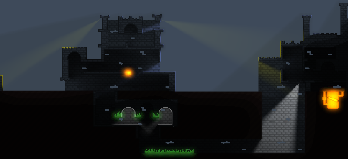
Now our project has realistic light, luminosity effects and updated dynamic light sources. Compare with the image from the first article, not so little difference, right?
Image from the beginning of this article.

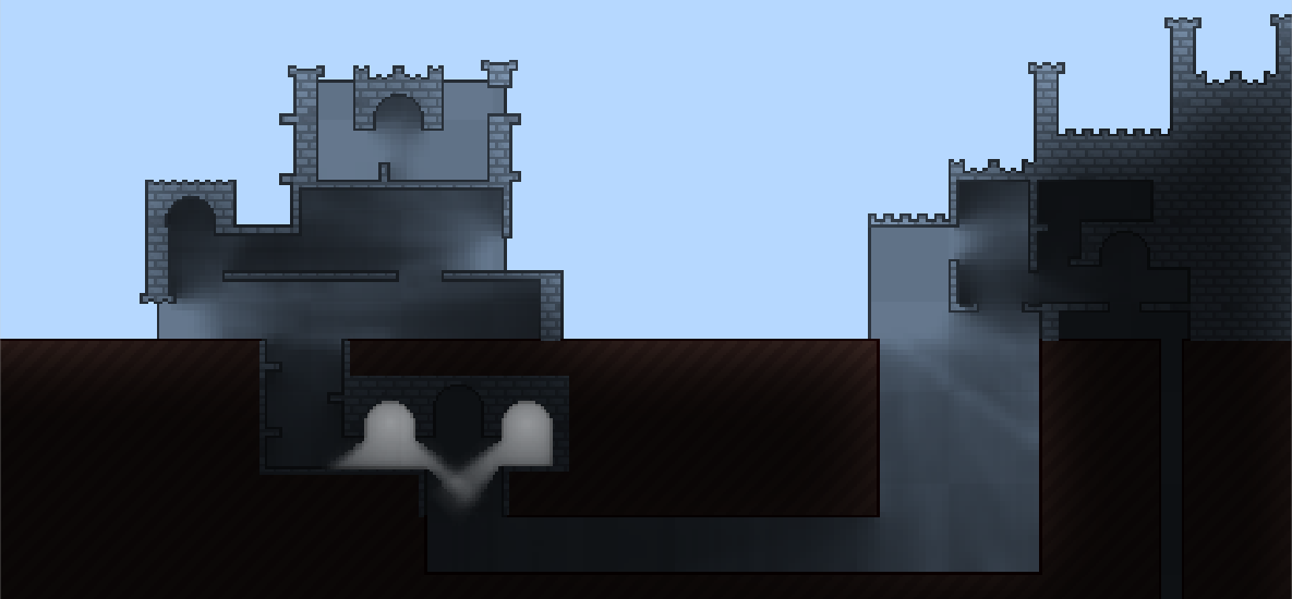
Image from the first part of the cycle.
And the most interesting thing: now that the lighting is ready and the algorithms and structure of the project have been refactored, it's time to write about the water!
Thanks for reading and comments on the previous parts and to the next article!
Source: https://habr.com/ru/post/313776/
All Articles