Soviet "Elbrus" - an overview of the architecture

About the subject of the article goes a lot of speculation - from the "Russian Barrows" to "unparalleled." This is due in no small measure to the lack of (accessible) full-fledged documentation, the few people who have dealt with them, and even a considerable amount of time that has passed since then. "Elbrus" has become one of the myths of a bygone era.
On the other hand, the computing complex undoubtedly existed and showed excellent results for its time. Perhaps due to the scarcity of the element base, which forced developers to invent various kinds of architectural tricks. Many of these tricks now look archaic, and some are quite relevant.
So the author, out of his inquisitive curiosity, tried to figure out the available documentation and create a more or less coherent picture. If the reader is interested in it - welcome under cat.
Element base
A new generation of technology arises not when a new generation of engineers has grown up, but on the basis of qualitative changes in technology. As for the Soviet “Elbrus”, such a change was the emergence of integrated circuits. For the "Elbrus-1", it was 133 chip series with TTL logic (speed 10 ... 15 ns per valve). For the "Elbrus-2" - the 100th series with ECL logic (speed 2 ns per valve).
')
100 series is made (serial production since 1974) on the basis of MECL 10K from Motorola (since 1971) [6]. 133 series (since 1969) was based on 54 series from TI (since 1965) [6]. Those. there was no particular lag in the element base at that time.
Memory organization
Physical memory
The memory subsystem was built on the basis of the K565RU3B ( NMOP ) microcircuit [3] with a capacity of 16Kbit and an organization of 16384x1.
Equipment correction and control allows you to correct single and detect double errors when reading information. To this end, eight bits of the Hamming code are formed and added to the 72-bit information word when recording. Thus, the word stored in the memory contains 80 bits, including: 8 - control information (tag), 64 - data, 8 - check bits of the Hamming code.
The address bus has a capacity of - 24, i.e. The size of physical memory is limited to 16 mega-words (72 bits each), 144 MB of data along with tags.
If we read along with the Hamming codes, we get 180 MB or 90 Kmcircume. All this was possible for the maximum configuration to place in 8 cabinets (sections OP).
In the maximum configuration includes 10 processors, with each processor connected to each section of the OP. The length of the communication lines is chosen approximately equal to 10 m from the condition of placement of devices of the complex. This length of light flies in vacuum for ~ 1/30000000 seconds (33 ns). In E-2, the signals are transmitted from the output register of the transmitting station to the receiver register in 80 ns (with a 44 ns duty cycle), which is very good.
Each memory cabinet (OP section) consists of four memory modules and a switch. The modules are functionally independent and can simultaneously exchange information with different processors. Only 32 modules, each with half a mega-word. With group access, all four modules are started simultaneously. This allows you to get the maximum rate of data exchange with the OP section.
The module's operation cycle is 13 clocks, however, successive calls to different chips of one group can be serviced every seven clocks.
At the lower level, the minimum block size - 16K words corresponds to the memory chip size of 16K bits. The block consists of 80 memory microcircuits, one microcircuit per discharge. Therefore, the memory module consists of 32 such minimum blocks.
The exchange device with RAM
It is part of the processor. It has a separate communication channel from each of the eight sections of the OP and can apply to each section both with single and with group requests.
In a group query, four words are exchanged in one call. The memory write access time for ECP is about eight clocks, the read memory retrieval time is about 20 clocks (the access can be delayed by the OU switch in case the memory module is busy or a conflict occurs with another CPU).
At the same time, up to three requests can be stored in the Unit. The Unitary Public Organization has internal paralleling into two channels, which makes it possible to simultaneously set two exchange requests to different sections of the OP. The maximum frequency of a channel change is one request per eight cycles. Thus, with group calls to the memory, the Unit will ensure the rate of exchange - one word per clock [1].
To optimize the work with a sequential crawl of addresses, a splitting technique (interleaving) is used. Some of the bits in the physical address are intermixed, as a result, successive words appear in different units of the above described memory hierarchy and can be read in parallel. The mixing scheme is as follows:
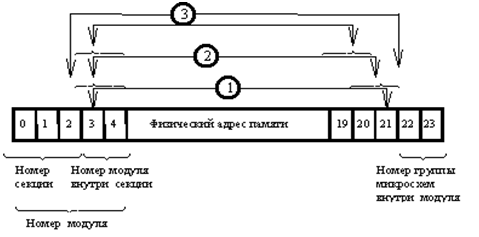
When excluding individual modules from the configuration, the operating system does not assign their addresses. The presence of a disabled module makes splitting impossible in this section.
Mathematical (virtual) memory
Mathematical memory is described by a 38-bit mathematical address, provided that the placement of the value with an accuracy of one digit is indicated (with a 32-bit address when specified with an accuracy of a machine word).
Values
The basic unit of information is value. Value is the logical unit of information that can be addressed using a mathematical address. Values are performed on operations when executing program commands.
Values can have the following sizes in bits (formats): 1, 4, 8, 16, 32, 64, 128.
None of the values other than 128-bit can be located in more than one word.
A single word can contain values of only the same type and format, with one exception: the whole and real format of 32 bits can be packed in one word in any order.
The control bits of the word stores information about the type and format of the values that are in the word.
Pages
Mathematical memory is paginated. Pages can be of various sizes (multiples of 16) - from 16 to 1024 words. The address of the beginning of the page has the lowest 10 (out of 38) digits of zero [2 p.61].
A block of 16 words located in a mathematical memory so that in the 38-bit address of the first word the lower 10 digits are zero, is called a string.
Segments
Segments are continuous addressing areas allocated by the system. The beginning of any segment in mathematical memory coincides with the beginning of a certain page.
To place a segment, use the page of the smallest possible size. Segments larger than 1024 words are placed in mathematical memory on adjacent pages, and all pages, except the last, should have a maximum size.
The beginning of the page, and therefore the segment, in physical memory can be placed at the beginning of any physical line. The page is located in adjacent cells of physical memory.
Therefore, a segment larger than 1024 words may not be fully present in physical memory (swapping), and its pages in physical memory are not required to go in a row.
Virtual memory support.
Virtual memory is organized in a rather logical and natural way. Segments are created by the OS kernel, which is inevitable, given the tag system and memory protection issues.
All free memory areas in the kernel are combined into an ordered list of free areas. Ordering is done by area size. In the command system there is specifically for this purpose the intended command “SEARCH BY LIST”, which finds either an area that exactly matches the size with the required one, or minimally exceeds the required size in size. In the first case, the found area is excluded from the list, loaded into the mathematical memory (if required), and a handle to this area is generated as the result of the procedure. In the second case, if the size of the found area exceeds the required one by more than 15 words, the area of the required size is taken from the found area, and the remainder is returned to the free memory area, where it will be included in the appropriate place in the free memory list. The user is given a handle to the memory area of the size that exactly matches the requested one.
In the event that there is no memory of the required size, an attempt is made to consolidate parts of free memory by moving smaller occupied areas that divide adjacent free areas into available free areas.
If this does not lead to the goal, pumping (swapping) of the occupied areas to external carriers occurs. This does not apply to running segments, you can simply release them ...
Each task has its own rollout file, and each segment knows its task. The allocation of free memory in the file is on the bit mask [2, p.143], in which one digit corresponds to the page. (For a mathematical memory of 2 ** 32, a mask of 2 ** (32-16) = 64K is required for a task, which is not so little. In addition, it is not clear how to deal with pages smaller than the maximum possible 8K.) Thus it is possible to avoid problems with maintaining the registry of free pages in comparison with the general download file. After all, each task has its own mathematical memory. In addition, the release of the entire memory of the process is reduced to the deletion of its pumping file, the work is transferred to the file system. With a relatively small number of tasks, this is an excellent approach. Its disadvantages can be attributed perhaps to the additional load on the file system.
In the OS kernel there is a task that “cuts” tasks in the background [2, p.143], discarding a certain percentage of pages. The data of passive tasks at the same time gradually appear in the pumping files, the actively working tasks are balanced.
Let us now analyze the transformation of addresses from mathematical to physical. All task memory areas (segments) are combined by a list, the head and tail of which are located in the task descriptor. Note that in this architecture there are no calls for a bare pointer in the spirit of “C”, the pair is always converted (pointer, offset).
In the mentioned list of task segments using the “SEARCH BY LIST” instruction there is a segment descriptor, and in it is the physical address of the desired page. If there is no page in physical memory, the swap mechanism is enabled.
To speed up the conversion of a mathematical address into a physical one in the CPU, an associative array of 64 elements is provided for the most “active” pages. The associative attribute is the number of the mathematical page, the answer is the physical address of the beginning of the page, its size, and also some service attributes. The search time in this associative array is 3 cycles, the processing rate is one application per cycle.
In addition, the word itself, which is accessed, along with its mathematical address is placed in the associative memory of words, which is also in each CPU. Such memory is an analogue of modern cache memory.
There is a mention [2, p.144] of the table of downloaded pages (TOC), designed to accommodate information about pages that have been rolled out or not yet initialized. The head of this table is in RAM, the overflow area is in the external memory (drum). Its value is proportional to the number of existing pages, and not the entire mathematical memory.
TOC is one for the system, so for each page, you must also remember the task ID.
To speed up work with TOC, a cache is provided in the kernel, and, as stated, is very efficient. But it is strange, because for effective caching it is necessary to understand the logic of the application of the task with memory, and it is unknown to OS developers.
So:
- Pages are pumped out to external media by the background task of the kernel “cutting” the task. Therefore, they go in TOC packs and (probably) in an orderly manner.
- Free space in the pumping files is distributed using the above-mentioned bit mask.
- But the pages are downloaded in an arbitrary order, determined by the logic of the work of applied tasks.
- Under TOC, they gave the fastest (and the smallest - up to 136 MB) external memory - drums , the average access time of 5-5.5 ms, the exchange rate of 3.6 MB / s [2, p.187]. As a comparison, for disks: the average access time is 60 ms, the exchange rate is 180 Kb / s.
- It is even more offensive if, in the course of operation, the TOC becomes fragmented and will require excess space. In addition, over time, TOC will lose orderliness and you will have to read the whole page to find the right page.
- Apparently, even though TOC is called a table, it is designed as a B-tree (1970) or, for example, similar to the DBM hash table (1979), cheap and cheerful. Rather, the first, given that the tree-like structure is used to allocate free memory by the file system [2, p.146]. On the other hand, in [2, p. 200] one can see regrets that segment management was too complicated and resulted in the use of a different RAM exchange interface with external memory used in the EU. With all the consequences.
Data types
As already mentioned, the word consists of 64 data bits and 8 control bits. Control bits contain a tag - a description of what lies in the information part of a word.
It may be:
- Empty 32 and 64 bit formats are usually uninitialized data. Dummies are quite possible to read, write, transfer to procedures and even check and change bits. But if you try to work with numbers or with arrays, an interrupt will occur.
- Integer format 32 and 64 bits - in contrast to the now common format, here the sign is highlighted in the most significant bit.
- Real 32 - sign of the mantissa / sign of the order / order of 6 digits / mantissa 24 digits
- Real 64 - sign of the mantissa / sign of the order / order of 6 digits / mantissa 56 digits
- Real 128 - the sign of the mantissa / sign of the order / order of 6 digits / mantissa 56 digits / high digits of the order - 8 digits / high digits of the mantissa - 56 digits. In general, the format of numbers differs from that of IEEE 754, which is now adopted. It is also taken from system 360.
- Bit
- Number - 4 digits, usually used to represent decimal numbers
- Byte - 8 bits, usually - a character string
- Set - 64 digits, a collection of similar elements that are not quantities and individual access to them is not allowed (SIMD?)
- The descriptor is 64 bits, the descriptor of the memory area, created only by the kernel, contains the mathematical address, the size in the elements, the size of the element in the bits, the type of memory protection. The maximum size of the area described by the descriptor is 2 ** 20 words.
- The index (indirect) word - 64 bits - is the loop counter in e-1.
It contains the current value of the counter, the cycle step, and the limit value (all by 20 digits + sign).
In arithmetic operations or operations of addressing the elements of an array, it is automatically converted to an integer; during cycle operations, an automatic check for going beyond the limit value occurs and the transition
at the address or automatically change the counter. - An indirect word has a descriptor structure and is distinguished by the fact that reading such a value automatically reads the value to which the address points (can be repeated several times).
- The interval is 64 bits, used to obtain a sub-region descriptor from the area described by the indexed descriptor.
- Label operation transition. Can only be used with the GOTO team. - 64 bits, contains
- The mathematical address of the context of the enclosing procedure within which this label is described. - 32 digits
- byte number from the beginning of the area - 16 bits
- program segment descriptor - 12 bits
- The lexicographic level of the procedure is 5 digits (0 is system calls, 1 & 2 are user procedures. 3 is the first executable ... [2, p.43]).
- Label procedure. It has the same structure, different tag, can only be used in the operations of entry into the procedure.
- Technical label. It has the same structure, different tag. When reading, there is an automatic entry into the procedure without parameters, which returns a single value.
- Semaphore - a means of synchronization in the system.
- Billet array. In the Elbrus system, it is not customary to explicitly call a getmem or maloc procedure.
Instead, a so-called array storage is put into memory — a word with a special tag, which indicates the size of the array and the size of the array element. If the array is never needed, the billet will remain billet. Otherwise, when reading such a workpiece, an interruption will occur, the processing procedure of which will allocate memory and write a descriptor of the selected array to the place of this workpiece.
Features of the command system
- The data is tagged, it allows the hardware to protect them as well as to simplify the system of commands, for example, replacing the whole family of typed addition commands with a single one - taking into account the tags.
- An addressless system of commands was adopted, as a result of which there is no unnecessary information about the distribution of registers. Effective dynamic allocation of registers implements the equipment. The unaddressed command format is based on the hardware implementation of the stack.
- The addressing of data in commands occurs on a pair — segment / index, taking into account the execution context, and not on the mathematical address. For example, the sequence number in the area of the stack allocated to a particular procedure.
- To call functions, in addition to the mathematical address, a fairly detailed descriptor is used, in which, among other things, the size of the local stack for data and parameters is specified. A deferred selection of data is implemented; when entering a function, only a segment descriptor is created, the actual selection occurs on the first call. It is reported [2 p.42] that this is an innovative technique. In fact, the function descriptor number comes with the call argument as well as the mathematical address of the code. In x86, for example, the compiler does all the auxiliary work, placing the prologue and the epilog of the function.
Addressless code.
We say “addressless instruction set”, we mean “ stack processor ”. Consider a simple example, the calculation of the expression x + y * z + u.
When building a parse tree with a compiler, it looks like this:
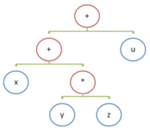
The assembly code (x86) for this expression is:
mov eax,dword ptr [y] imul eax,dword ptr [z] mov ecx,dword ptr [x] add ecx,eax mov eax,ecx add eax,dword ptr [u] For a hypothetical stack engine, pseudocode is:
push x push y push z multiply add push u add Operations with the stack require the following types of operations:
- write element to the top of the stack (push)
- remove item from the top of the stack (pop)
- binary operations that remove two elements from the top of the stack and record the result of the operation (+ - * /)
- unary operations, replace the result at the top of the stack (change sign)
What does the architecture of Elbrus offer us?
- Load operations to the stack. Information can be loaded onto the stack either directly from the command thread or from the data area. In the first case, the load value is in the command itself, in the second case, the value is loaded to the address located either in the command or at the top of the stack (load by address).
Note that since the stack is implemented as a cyclic buffer from the registers, loading a new element can cause the automatic unloading of a part of the stack into memory.
Of particular interest is the download at the address at which:- on the address pair is the mathematical address of the value
- this checks the ability to access the value
- the value is loaded to the top of the stack
- next cycle
- the tag checks the class of values of the loaded value
- if the value belongs to a class of values, the operation is completed
- if it is an indirect word, an indirect word is read
- procedure label is quite a value, the loop stops
- if this is a technical label of the procedure, the procedure is called which should leave its result at the top of the stack
- Write to memory from stack. To do this, we need two values from the top of the stack: the value and the address of the record. The address of the entry can be either an address pair or an indirect word. The entry is made “one-step”, that is, directly at the address of the entry.
- Arithmetic operations , relational operations and logical operations. Arithmetic operations are performed on one or two values contained in the top of the stack. As a rule, the operands are whole or real, and, if the operands are of different types (whole and real), then before the operation, the whole is automatically transformed into real. If the operands have different formats, before the operation, an automatic “length alignment” is performed along the longest length.
Initial numbers are removed from the stack (with a corresponding pointer offset), and then the result is placed at the top of the stack.
Single-place arithmetic operations take an operand from the top of the stack and replace it with the result.
CPU
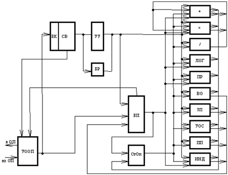
The block diagram of the CPU [1]:
- memory exchange device
- 512-word command buffer memory (BC) for coordinating the rate of decryption of commands and calling a program from RAM
- control device (CU)
- 10 specialized actuators (DUT) to execute commands
- base registers (BR) for converting relative addresses to absolute
- 256-word operand stack (STOP) for storing intermediate results of operations
- buffer memory (PSU) of 1024 words, is intended for storing global data plus buffer memory of 256-word arrays with preliminary paging
- CB - sampling (decoding) scheme
Decoding
The program code is read into the command buffer (BC). BC works as an associative array, has a volume of 512 words, which are divided into 32 equal segments. Swapping information in the BC from the RAM is performed in blocks of four words. The paging rate is determined by the required supply of command words in the instruction buffer and is automatically adjusted when the decoding rate of the commands changes.
The sampling scheme extracts the next command from the BC, decrypts it and transmits it to the CU for conversion to the internal register format.
Internal Addressing System
All transfers of address and numeric information are accompanied in the CPU by the internal address of the source or consumer of information. Internal addresses are assigned to the instruction buffer, a stack of operands (Stop), a power supply unit, and some input registers of the DUT.
The STOP consists of 32 registers and a 32-bit register - bit mask. Each bit in this mask is responsible for a specific register, 1 means busy, 0 means free.
When issuing a command in the DUT, the internal addresses of the operands and the result of the operation are formed. For stack operations, the operands and the result are register numbers from the Stop.
To decode the summation command, for example, it is considered that the numbers of the operands have already been obtained earlier, you can assign any free register from the Stop. After the command is executed, the operands are released.
Execution
Not all commands can be executed directly after their decoding; therefore, a buffer of decoded but not executed commands is necessary. The CPU has this buffer for 32 commands in the internal representation.
Commands from the decoder are issued in the sequence specified by the program. In this case, they are sequentially numbered and this number accompanies the team throughout its life. This number is the index in the aforementioned decoded instruction buffer, when it reaches 32, it starts from zero again. Knowing the current value, you can line up all the commands in the queue in order of their decoding.
The execution time of commands in the DUT is determined by their type and ranges from 2 to 20 clocks for operations on single-precision operands (32) and up to 30 clocks over double-precision operands (64). ??? Multiplication (F64) - 4 bars. Division (F64) - 24 bars.
Performing operations on real numbers of the F128 format requires a threefold addition — the addition of the lower digits, the addition of the higher digits, taking into account the transfer from the lower digits, and the repeated addition of the lower digits, taking into account the transfer from the higher digits. This requires station storage intermediate results.
Execute commands begin on the availability of arguments and the availability of the desired actuator. Since the order of execution does not necessarily coincide with the original, we have an extraordinary execution ( OoO ). And since there are several execution units and they work in parallel, there is superscalarity . True, the adder, divider and multiplier in a single copy, but can work in parallel.
Given that there are 10 actuators in total, the question arises, how many instructions per clock can be executed. In [2 p. 185] it is mentioned that in the technological mode with sequential execution of commands, the productivity drops by a factor of 2-3. [4] talks about 2 teams per clock. This is due, apparently, to the implementation of the Stop, which allows only two entries per clock.
Example
To demonstrate the possibility of a completely superscalar behavior, consider the expression “(a * b) + (c / d)”. At the same time, the variables “a” & “c” are located in the region of local variables of the procedure and are present in the cache, and the “b” & “d” are global and not in the cache. For simplicity, they are all F64 type.
The assembler code looks like this:
b ∗ c d ⁄ + Where OT means “evoke value”, DVZ means “long OT”, and the mnemonics of arithmetic operations are unknown.
After decoding, the code in the internal representation is approximately as follows (mnemonics are invented):
a -> R1 ; R1 b -> R2 ; R2 ∗ R1 R2 ->R3 ; R2 , R1 & R2 -> R4 ; R4 d -> R5 ; R5 ⁄ R4 R5 ->R6 ; R6 , R4 & R5 + R3 R6 ->R1 ; R1 , ; R3 & R6 ; R1 Due to the dependencies between the commands, execution occurs in the following order (2 instructions per clock, loading from the cache - 1 clock, loading from the memory, 13 clock cycles, “*” - 4 clock cycles, “/” - 24 clock cycles, “+” - 3 clock cycles ):
| tact | Start | Turned |
| one | loading a -> R1; boot b -> R2 | |
| 2 | boot with -> R4; boot d -> R5 | Loaded a -> R1 |
| 3 | boot with -> R4 | |
| 13 | boot b -> R2 | |
| 14 | ∗ R1 R2 -> R3 | boot with -> R4 |
| 15 | ⁄ R4 R5 -> R6 | |
| 17 | ∗ R1 R2 -> R3 | |
| 38 | ⁄ R4 R5 -> R6 | |
| 38 | + R3 R6 -> R1 | |
| 40 | + R3 R6 -> R1 |
Multiplication and division are quite parallel. Alas, arithmetic actuators do not have pipelines that were planned only in a vector processor [2, p.150].
Stop and continue execution
Sometimes it may be necessary to pause the program, with the option to continue, if necessary, for example, when a time slice expires. This requires restoring the original order of instructions. Wherein:
- remember the number of the command that caused the interrupt
- the commands decrypted before it are completed, and the execution of commands decrypted later is canceled
- registers are restored to the moment corresponding to the decoding of the command that caused the interrupt
- enter interrupt
Restoring the status of registers will require a special mechanism, for example, a cyclic buffer for the log of changes in register values of 2 * “maximum instruction length in cycles”. At the end of the instruction, this log is written to the old register value from the Stop, the new value, the register number and the command number. Then, if necessary, you can unscrew the changes for the commands being canceled.
Cancel command execution is also used when processing conditional jump commands. Thus, speculative execution of the code is carried out .
About the predictor of the direction of branching there is a mention [1], but the mechanism is unclear.
So what do we have?
- superscalar level 2 instructions per clock
- for the implementation of superscalar use of the technique of scoreboarding , no renaming of registers , as indicated in [5], and there is no close, this technique is simply not applicable here
- use of the operand stack close to the register window technique, which appeared independently, but several years later (E-1: raz. 1973-1979, Berkeley RISC: 1980-1984)
- extraordinary command execution
- speculative conversion prediction
- the combination of unaddressed architecture and superscalarity in Elbrus-1 seems to take precedence
Multiprocessing
The problem of interprocessor interaction is associated with the presence of each processor’s own POPs (cache) and, consequently, matching the data in the RAM and POPs. POPs can significantly reduce the frequency of calls to relatively slow memory, but it is possible that the data in the memory is fresh to POPs.
In the Elbrus MVK, a task can generate several processes (threads) that share a common mathematical memory. A program section that uses (reading or modifying) data common to several processes is called a critical section.
There are two problems - synchronization and cache coherence support.
Semaphores :
- A semaphore is a data type in the command system that has its own tag [2 p.121]. An unprivileged user cannot change the contents of the semaphore. It can only submit a semaphore by name as a parameter to synchronization procedures (semaphores cannot be copied and each semaphore exists only in one instance, however several links can be established for each semaphore)
- A semaphore may be “open” or “closed”.
- The “WAIT” function (with the argument referring to the semaphore) blocks (puts it in the semaphore queue) the current thread if it is closed or does nothing if it is open. After unblocking, thread will continue execution with the next instruction after calling this function.
- The function “OPEN” (...) puts the semaphore in the open state, all processes waiting for its opening (threads) are transferred to the queue ready for execution
- The “SKIP” (...) function transfers all processes (threads) locked on this semaphore to the category of ready for execution, the semaphore remains closed
- The “CLOSE” function (...) places the semaphore in the closed state if it has been opened. If the semaphore has been closed, then the current thread is blocked and put in the semaphore queue. The difference from the “WAIT” function is that when this thread is unlocked, an attempt will be made to close the semaphore again.
- The “OPEN” function is privileged [2,124], the first operand should be a spinlock, and the second should be an ordinary semaphore, atomically opening the first semaphore and closing the second one. producer-consumer. For example, processes exchange portions of data, when the consumer must receive a signal that a new portion of data is ready, and the producer that the consumer has processed the previous one. The solution to this problem on two semaphores is that one semaphore is used to alert the manufacturer and the other the consumer.
- For privileged users, operations with spinlocks are available - “ZHUZH” (yes, from the word buzz [2 p. 124]) and “OPEN”, similar to “CLOSE” and “OPEN”. These operations are noticeably faster, but are only suitable for short-term work, while interruptions are not allowed (work with virtual memory and devices). It is impossible to work simultaneously with a semaphore as with a semaphore and as with a spinlock.
- Users are responsible for the correct use of this technology. For example, if a process opens a semaphore that was not closed to them, then the process that closed the semaphore loses its monopoly on working with the data protected by this semaphore. In addition, this technique does not guarantee the absence of dead ends .
- When the semaphore is closed, the time of this event is remembered, it will still be useful to us.
Memory coherence
It is believed that working with common data can only be done in the critical section, that is, between the operations "CLOSE" and "OPEN" or the operations "LUTURE" and "OTKSEM."
All data recorded in the processor's POPS between these operations are marked as “common” and, in addition, the time they are recorded in the POPS is remembered. Under the POPs mean the global data memory of 1024 words [2 p. 186].
Each procedure has its own local address space, global data belongs to other procedures, as far as the scope of the procedure allows. Those. for the compiler and for the processor, references to local and global data are unequal.
When a semaphore is opened, an opening time is recorded in it. Each time the semaphore is closed, the time recorded in it and the time of recording general data in the POPS are analyzed. Those common data that hit the POPs before the discovery of this semaphore is no longer reliable, since they could be changed by another CPU. Those data that fell into the POPs after the opening of the semaphore, reliable, since they are not related to this semaphore.
We will understand by example. Suppose we are talking about a flow-safe counter.
- flow-1 captures (closes in terms of Elbrus) semaphore-1 on CPU-1 at time T-1
- thread-1 reads variable counter-1, which was not in the global cache
- thread 2 tries to capture semaphore 1 and is blocked
- Now counter-1 has appeared in the global cache CPU-1 with time T-2
- thread-1 increments and writes counter-1 to the global cache CPU-1 over time T-3
- flow-1 frees up (opens in terms of Elbrus) semaphore-1 with time T-4. At this moment, a change in counter-1 is detected within the semaphore-1 capture time and this value is recorded in memory, now it is available to all
- Stream-2 woke up at the time of T-5 on CPU-2 with a captured (closed) semaphore-1
- thread-2 is trying to read the value of counter-1, which is already in the global cache of CPU-2 with time stamp T-0. Since T-0 is less than T-5, the value is considered invalid and read from memory.
- flow-2 frees up (opens in terms of Elbrus) semaphore-1 with time T-6. Since nothing has changed, nothing happens
Thus, based on a comparison of the opening time of the semaphore and the time of entry of common data into the POPS, the CPU unambiguously solves the problem of data reliability. You do not need to reset the entire global cache, which would hurt performance.
To ensure all this, instructions are introduced for inter-processor communication:
- “PREVATCH” with an argument - mask of interested processors. As a result, all specified processors receive an interrupt.
- “WAITING” - the command execution is waiting for the execution of the “RESPONSE” command from all processors specified in the command (command parameter)
- “RESPONSE” - confirmation of receipt and execution of the interrupt
Apparently, this is how the information on the state change of semaphores is distributed.
Also, presumably, in this way, the data that are recorded into the POPs by the hardware without closing any semaphores should be distributed. This includes program segment descriptors and math and physical address mapping tables.
In the same way, it would be possible (would) solve the problem of delivering changes to a POPs while closing a semaphore to POPs of other processors.
Function call
Function call parameters and local variables are on the stack. The call context is also on the stack. In essence, the context consists of two pointers — to the old context (that is, the contexts are linked by a list for exiting functions) and to the instruction with which the call occurred. Plus additional information, all this was able to pack in two words.
But the call of functions in Elbrus is peculiar. It is multi-phase.
- First we need to create the context of the future call and place it on top of the stack (marking the stack)
- We calculate the call parameters that appear on top of the stack in the right order. Thus, the parameters are located after the context and can be accessed via the local data area descriptor using the general hardware protection mechanism.
- Memory is allocated (the size of which is defined by the compiler) for local data. And that's it, you can start the execution of the function.
When exiting, if necessary, the function leaves the return value at the place of its former context.
Why so difficult? Why not call a function more traditionally, with one instruction?
In this case, the parameters of the function will be in front of the context and the descriptor of the local data area, which starts from this context will not be able to cover them. If you move the descriptor back to the beginning of the parameter area, the list of the call stack breaks, or you have to add a pseudo-parameter to the stack — the length of the parameter area. What is actually the same stack marking.
As for the mentioned descriptor for access to local data, it is not one, there are 32 of them. And which of them is used is determined by the lexicographic level of the function.
Lexicographic level of procedures.
This mechanism is somewhat similar to the x86 privilege level . There are 32 base registers of descriptors that describe the local data of the procedures (+ parameters) on the stack.
Each (as a regular domain descriptor) contains:
- 32 ... 38 bits - the mathematical address of the beginning of the region being described (“MANACH”)
- 13 ... 18 digits - maximum index or size (“INDMAX”)
- 3 digits - descriptor step 2 ** n bits (n = 0,1,2, ..., 7) (“STEPDESS”)
- 4 digits - access mode information (“PROTECTION”)
Different base registers describe different stack contexts. Thus, register No. 0 contains a descriptor describing the stack of descriptors of procedures and data of operating systems, registers No. 1 and No. 2 describe stacks of procedure descriptors and external names of the task being performed, register No. 3 contains a descriptor describing the stack of the top level block and so on.
Thus, if some instruction instructions contain an encoded "name" of a value (physically located on the stack), then it is defined only in this context. Access to the stack element is carried out through the lexicographic level of the function, and the sequence number of the word in the stack area allocated for the data of this function (address pair).
FORTRAN, COBOL, LISP, APL - languages that do not have a block structure
In the procedures of such languages, only local variables and call parameters are available. Memory allocation for each called procedure is performed dynamically. Upon entering the procedure, it is allocated in the stack the necessary free memory area for the formal parameters and local variables, the stack pointer (US) moves to the new boundary.
The memory area allocated to the procedure is described by a descriptor placed in one of the basic registers (even N). Appeal to the value in this area is carried out using the address pair (N, I).
The area of free memory in the stack below the new border is used to store intermediate results.
, . , , , , .
Q, Q , . , , , Q.
When exiting the Q procedure, it is necessary to restore the contents of the base register with the number N and transfer control to the operator following the operator of the procedure Q call. :
- MKS - the stack marker is similar to the descriptor, contains the size of the procedure data area, and its own address is the start address of this area. Top down:
- 32 bits - mathematical address of the previous ISS (“ADDRESS”)
- 1 bit - a sign of blocking the recording of address information (“BL”)
- 1 digit - a sign of privileged procedure (“REG”)
- 19 bits - the size of the memory area in the stack allocated for the procedure (“SIZE”)
- 2 digits - return type: no value; 1 word; 2 words (“”)
- 5 digits - reserve
- 4 — (“LL”)
- — — , .
- 18 — “Δ ”
- 3 — “”,
- … , …
- 16 — “Nk”,
- 11 — “”, , , , (Nk & )
- 4 —
- ...
Q :
- Q, , Q.
- “” — . Wherein:
- , Q
- “Δ ” ( , ), . . , .
- , .
- “”.
“”, :
- () , , 0
- (“”) ,
- , “Δ ” ( ) “” , , () .
- , . “” , Nk — , .
60, /1, , 68 —
, , .
, — & . , . 2 .
, , . ?
. , 32 , 3 . . Those. ( ), , . , — 30 32 .
— N Q P . , ( ) P .
, — . , :
- . , ()
- “LL”
- “” ,
- LL
. , — , , . — . ?
. , .
? , .
For example:
procedure p; begin integer i; ... begin integer array s [1:1000]; ... end ... end , P 1001 , 1 . , , .
? ( 50% :). , , ( , ) , .
, “” ( , -) [9]. . , “” .
Total
. “”. , , , … .. , ( ) — “, ?”.
, , , . , “” . , , ( , ) , .
, “” , , , , , .
[2, 201] ( 80 Mflops [2, 166]), .
Sources
[1] .. lectures
[2] . ( , )
[3] WIKI
[4] www.osp.ru/os/2009/02/7314081
[5] www.ixbt.com/cpu/e2k-spec.html
[6]
[7] www.pvsm.ru/programmirovanie/106969
[8] www.caesarion.ru/warrax/w/warrax.net/88/elbrus.html
[9] www.mcst.ru/files/511cea/886487/1a8f40/000000/book_elbrus.pdf
UPD: wasya , , , ,
Source: https://habr.com/ru/post/313376/
All Articles