Mikrotik: VLAN using a switching chip
Mikrotik equipment is rich in features, but unfortunately, developers do not always have time to keep the Wiki with the documentation up to date, sometimes the information refers to the outdated version of RouterOS or it doesn’t reveal little details. Today I want to add a little to the official Wiki, talking about configuring the built-in switching chip to work with VLAN. As experimental we have: RB951Ui-2HnD and CRS125-24G-1S-2HnD. Everything is done on RouterOS 6.37.1
So, around a lot of articles, where I work with a VLAN on a CPU (they announce the VLAN on the interface and put it in the Bridge). Such a bundle has the right to life, but in its work we spend CPU resource, which can be very valuable. Two different devices represent different configuration mechanisms for the switching chip, since they are very different technically.
We will implement some examples from the official Wiki :
')
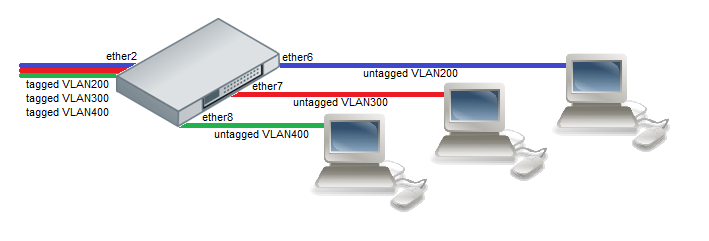
Let us clarify the picture: Tagged packets (trunked port) come to the ether2 port, and unprocessed packets go to the ether6-ether8 ports (access ports - client ports).
I will take the configuration from a really working device, so there will not be full compliance with the picture.
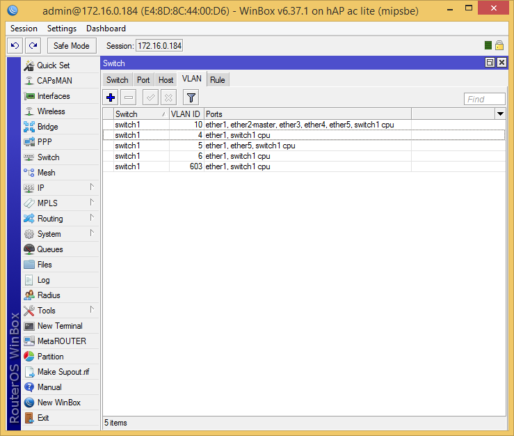
Configuration: Tagged packets come to ether1 (VID: 4,5,6,10, 603), stripped VID: 10 leave ether2-ether4 ports, stripped VID: 5 leaves ether5, VID: 603 is not used now, and a special port switch1-cpu accepts any packets.
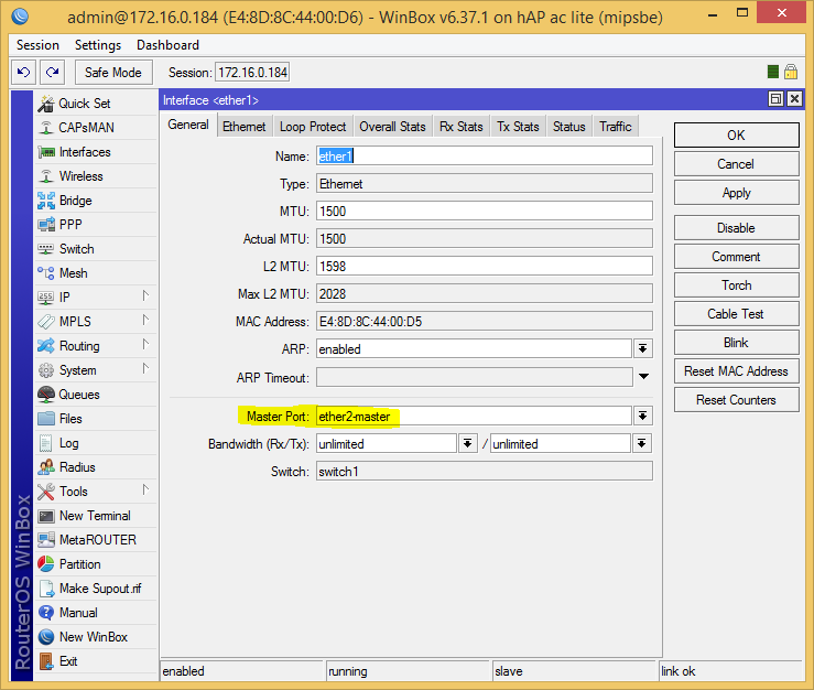
First, we will create a switching group, for this, we will set up the master port in all interfaces (by default ether2-master), thus we will give these ports to the switch management.
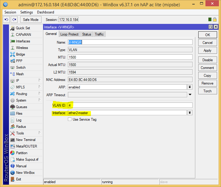
Similarly for all others. Without delaying, the master port (so we will get access to this VLAN from the CPU, in fact, we associate it with switch1-cpu), we hang the VLANs we need:
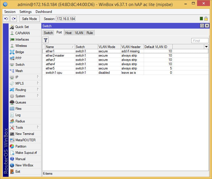
Next, we will define the packet processing policy on the ports (VLAN number by default), what to discard, what to strip, and where to tie the scarf:
You can read about the parameters in the Wiki in the Vlan-table section.
Next, we will create a VLAN table, according to which the chip will work with tags:
That's all, now the VLANs are serviced on the switching chip, unfortunately, the RB951Ui-2HnD has not very big capabilities, for example, it cannot make a hybrid port, then you have to build a forest of crutches on the bridge.
Here the switching chip is completely different, and can do more, let's get started:
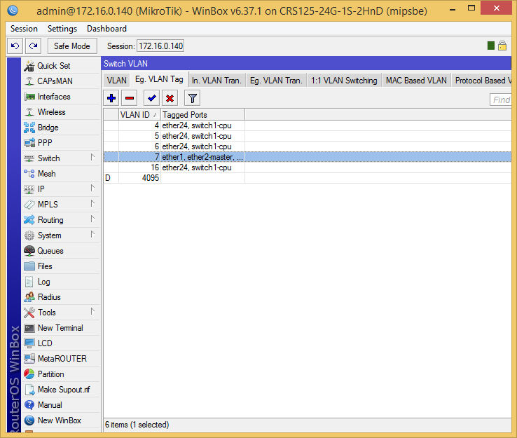
Configuration: Tagged packets come to ether24 (VID: 4,5,6,7,16), from the ether1-ether23 ports go stripped VID: 16 and dressed VLAN: 7 (for the second example), and the special port switch1-cpu accepts any packages.
First, we will create a switching group, for this, we will set up the master port in all interfaces (by default ether2-master), thus we will give these ports to the switch management.
Similarly for all others. We will hang the VLANs we need on the master port:
Next, we will create a VLAN table, according to which the chip will work with tags:

Next, we define a policy for processing packets on the ports, here everything is richer, the policy is set separately.
Let's set the ports on which the corresponding VLAN will be dressed on exit:
Now, on which ports, the outgoing VLAN should be stripped:

Literally, it is described as follows: if VID: 16, port 1 to 23, install a new VID: 0 (strip).
Now, on what ports, the incoming packet should be put on the VLAN:
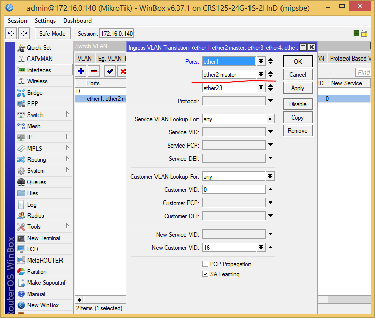
Literally, it is described as follows: if VID: 0 (packet is stripped), port 1 to 23, install a new VID: 16 (put on).
With this all.

Here we consider only the CRS125-24G-1S-2HnD, unfortunately, RB951Ui-2HnD is no longer able to do this on the switching chip.
So, take the complete conf from the previous example, and add the following rule:
Introduction
So, around a lot of articles, where I work with a VLAN on a CPU (they announce the VLAN on the interface and put it in the Bridge). Such a bundle has the right to life, but in its work we spend CPU resource, which can be very valuable. Two different devices represent different configuration mechanisms for the switching chip, since they are very different technically.
We will implement some examples from the official Wiki :
Port Based VLAN
')
Let us clarify the picture: Tagged packets (trunked port) come to the ether2 port, and unprocessed packets go to the ether6-ether8 ports (access ports - client ports).
I will take the configuration from a really working device, so there will not be full compliance with the picture.
RB951Ui-2HnD
Configuration: Tagged packets come to ether1 (VID: 4,5,6,10, 603), stripped VID: 10 leave ether2-ether4 ports, stripped VID: 5 leaves ether5, VID: 603 is not used now, and a special port switch1-cpu accepts any packets.
First, we will create a switching group, for this, we will set up the master port in all interfaces (by default ether2-master), thus we will give these ports to the switch management.
/interface ethernet set ether1 master-port=ether2-master Similarly for all others. Without delaying, the master port (so we will get access to this VLAN from the CPU, in fact, we associate it with switch1-cpu), we hang the VLANs we need:
/interface vlan add interface=ether2-master \ name=V-210 vlan-id=10 add interface=ether2-master \ name=V-MNGR vlan-id=4 add interface=ether2-master \ name=V-PR1 vlan-id=603 add interface=ether2-master \ name=V-WL vlan-id=5 add arp=enabled arp-timeout=auto disabled=no interface=ether2-master \ loop-protect=default loop-protect-disable-time=5m \ loop-protect-send-interval=5s mtu=1500 name=V-WLG use-service-tag=no \ vlan-id=6 Next, we will define the packet processing policy on the ports (VLAN number by default), what to discard, what to strip, and where to tie the scarf:
/interface ethernet switch port set ether1 default-vlan-id=10 vlan-header=add-if-missing vlan-mode=secure set ether2-master default-vlan-id=10 vlan-header=always-strip vlan-mode=secure set ether3 default-vlan-id=10 vlan-header=always-strip vlan-mode=secure set ether4 default-vlan-id=10 vlan-header=always-strip vlan-mode=secure set ether5 default-vlan-id=5 vlan-header=always-strip vlan-mode=secure set switch1-cpu default-vlan-id=0 vlan-header=leave-as-is vlan-mode=disabled You can read about the parameters in the Wiki in the Vlan-table section.
Next, we will create a VLAN table, according to which the chip will work with tags:
/interface ethernet switch vlan add ports=ether1,ether2-master,ether3,ether4,ether5,switch1-cpu switch=switch1 vlan-id=10 add ports=ether1,switch1-cpu switch=switch1 vlan-id=4 add ports=ether1,ether5,switch1-cpu switch=switch1 vlan-id=5 add ports=ether1,switch1-cpu switch=switch1 vlan-id=6 add ports=ether1,switch1-cpu switch=switch1 vlan-id=603 That's all, now the VLANs are serviced on the switching chip, unfortunately, the RB951Ui-2HnD has not very big capabilities, for example, it cannot make a hybrid port, then you have to build a forest of crutches on the bridge.
CRS125-24G-1S-2HnD
Here the switching chip is completely different, and can do more, let's get started:
Configuration: Tagged packets come to ether24 (VID: 4,5,6,7,16), from the ether1-ether23 ports go stripped VID: 16 and dressed VLAN: 7 (for the second example), and the special port switch1-cpu accepts any packages.
First, we will create a switching group, for this, we will set up the master port in all interfaces (by default ether2-master), thus we will give these ports to the switch management.
/interface ethernet set ether1 master-port=ether2-master Similarly for all others. We will hang the VLANs we need on the master port:
/interface vlan add interface=ether2-master \ name=V-MNGR vlan-id=4 add interface=ether2-master \ name=V-WL vlan-id=5 add interface=ether2-master \ name=V-WLG vlan-id=6 Next, we will create a VLAN table, according to which the chip will work with tags:
/interface ethernet switch vlan add learn=yes ports="ether24,switch1-cpu" vlan-id=4 add learn=yes ports="ether24,switch1-cpu" vlan-id=5 add learn=yes ports="ether24,switch1-cpu" vlan-id=6 add learn=yes ports="ether1,ether2-mast\ er,ether3,ether4,ether5,ether6,ether7,ether8,ether9,ether10,ether11,ether1\ 2,ether13,ether14,ether15,ether16,ether17,ether18,ether19,ether20,ether21,\ ether22,ether23,ether24,switch1-cpu" vlan-id=7 add learn=yes ports="ether1,ether2-mast\ er,ether3,ether4,ether5,ether6,ether7,ether8,ether9,ether10,ether11,ether1\ 2,ether13,ether14,ether15,ether16,ether17,ether18,ether19,ether20,ether21,\ ether22,ether23,ether24,switch1-cpu" vlan-id=16 Next, we define a policy for processing packets on the ports, here everything is richer, the policy is set separately.
Let's set the ports on which the corresponding VLAN will be dressed on exit:
/interface ethernet switch egress-vlan-tag add tagged-ports=ether24,switch1-cpu vlan-id=4 add tagged-ports=ether24,switch1-cpu vlan-id=5 add tagged-ports=ether24,switch1-cpu vlan-id=6 add tagged-ports=ether24,switch1-cpu vlan-id=16 Now, on which ports, the outgoing VLAN should be stripped:
/interface ethernet switch egress-vlan-translation add customer-vid=16 new-customer-vid=0 ports="ether1,ether2-master,ether3,ether4,ether5,ether6\ ,ether7,ether8,ether9,ether10,ether11,ether12,ether13,ether14,ether15,ethe\ r16,ether17,ether18,ether19,ether20,ether21,ether22,ether23" Literally, it is described as follows: if VID: 16, port 1 to 23, install a new VID: 0 (strip).
Now, on what ports, the incoming packet should be put on the VLAN:
/interface ethernet switch ingress-vlan-translation add customer-vid=0 new-customer-vid=16 \ ports="ether1,ether2-master,ether3,ether4,ether5,ether6,ether7,ether8,ethe\ r9,ether10,ether11,ether12,ether13,ether14,ether15,ether16,ether17,ether18\ ,ether19,ether20,ether21,ether22,ether23" Literally, it is described as follows: if VID: 0 (packet is stripped), port 1 to 23, install a new VID: 16 (put on).
With this all.
Example 2 (Trunk and Hybrid ports)
Here we consider only the CRS125-24G-1S-2HnD, unfortunately, RB951Ui-2HnD is no longer able to do this on the switching chip.
So, take the complete conf from the previous example, and add the following rule:
/interface ethernet switch egress-vlan-tag add tagged-ports="ether1,ether2-master,ether3,ether4,ether5,ether6\ ,ether7,ether8,ether9,ether10,ether11,ether12,ether13,ether14,ether15,ethe\ r16,ether17,ether18,ether19,ether20,ether21,ether22,ether23,ether24" \ vlan-id=7 Source: https://habr.com/ru/post/313248/
All Articles