Architecture and programming computer Vectrex
- Does he have a video output?
- And how do you imagine this?
(from talking about Vectrex)
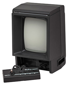 Vectrex was produced by GCE in 1982-1983. and is a gaming computer (console) whose key feature, a vector display, makes it one of the most unusual and interesting 8-bit computers. With some stretch we can say that it is a simplified version of Cinematronics , more technically advanced vector slot machines.
Motorola 6809 is used as a processor in Vectrex - it is similar to MOS 6502/6510, but 16-bit registers, additional addressing modes, multiplication are added.
Clock frequency - 1.5MHz.
')
Since the computer was released as a game console and games were sold for it on cartridges, the program is placed in the cartridge ROM (32 KB), and the RAM is quite tiny (1 KB - two pieces 2114) and is intended more for data.
There is also a built-in ROM with BIOS (8 kb - one 2363), which includes a set of routines for drawing vectors and text output, several primitive melodies and even one game - Minestorm (many known as Asteroids).
The sound is implemented on the AY8912 chip (also used in MSX2 and later ZX Spectrum), however, in addition there is a regular possibility to play 8-bit sound through the DAC (the practical application of this method, however, is limited).
Vectrex is designed as a monoblock (including a CRT screen), but the keyboard is not provided in principle. Management is carried out by two joysticks (including analog). In addition, a light pen and 3D Imager glasses can be connected.
From 1982 to the present time, about 150 games have been written for Vectrex, several serious programs (such as editors of graphics, music, animation), as well as about a dozen demos and intro . Interestingly, more than half of the games (and all demos) are released after 1995, i.e. a decade after the cessation of production and support for Vectrex. The revival of the platform is connected, first of all, with the advent of good emulators, which made the development available to anyone. The computers themselves are also quite accessible on eBay.
 Except for the image output part, the Vectrex architecture is fairly common for computers of that period. The main interest is the subsystem that forms the vector image, and much of the article will be devoted to it.
Vector displays, now practically unheard of and little known, were common in the 1970s.
The main difference from the well-known raster is the lack of automatic scanning. The beam does not run along the lines itself. Its movement is controlled by the program - the code you write determines the direction, speed, duration and brightness with which the beam will move. As a result, the vector display has no pixels, and, therefore, no concept of “resolution” (at least in the usual sense).
In fact, such a display is an oscilloscope, to the horizontal (X), vertical (Y) and brightness channel (Z) of which digital-to-analog converters are connected.
To get a line on the screen, you need not just to move the beam from one point to another, but to do it evenly and at the desired speed. Then the beam can be extinguished and moved to another point, where to light and move to the third, etc. Thus we get some figure.
After the transfer is completed, the phosphor will glow for a while and the line will be visible. However, this afterglow does not last long.
For this reason, all that is required, including the execution of the code, the delays caused by the call to the periphery and the very drawing of the lines, must be completed in a limited time.
If there are many lines, the image will begin to flicker. This makes it impossible to create shaded shapes (unless they are very tiny), and any serious things will have to be written in assembler because, even if you imagine a perfectly optimizing compiler, calculate all the time delays when the beam moves that will occur in the output code, problematic - one extra load in the register in the wrong place can completely distort the image.
If for traditional 8-bit platforms (such as Commodore VIC-20, C64 or ZX Spectrum) it is possible to program without ever looking at the computer circuit, in the case of Vectrex, understanding how the image forming part works is necessary.
Of course, you can use ready-made BIOS routines for drawing lines, simple shapes, and displaying labels, but this does not allow you to fully use the capabilities of the device - sooner or later you will still have to work with the hardware directly.
For this reason, familiarity with the development will be closely intertwined with a description of the computer device.
We will deal with the example of constructing a straight line from a point where the beam was already located, to some new given point.
In this context, we are interested in the following Vectrex'a components (numbers in the diagram are shown in brackets):
MOS 6522 (IC207) - the universal interface adapter (VIA - Versatile Interface Adapter) - this chip maps to the memory area $ D000 ... $ D00F. Accordingly, writing to these addresses of values (for example, instructions of the processor STA $ D00x) leads to a change in its registers.
6522 contains, in particular, I / O ports, two timers, shift register.
Details are better seen in the documentation on the chip (see the link to the archive at the end of the article), but the point is that, by writing the microprocessor commands to the above-mentioned memory cells, we set the legs sticking out of the chip to 0 or 1 (and also vice versa). we can check if they are 0 or 1).
MC 1408 (IC301) - 8-bit digital-to-analog converter (DAC, DAC). Converts the code received from the 6522 chip to the appropriate voltage level. In terms of programming, the voltage range corresponds to the numbers -128 ... +127 (and not 0 ... 255!)
LF347 (IC303) - s & h (store & hold) sampling-storage circuits on operational amplifiers. Keep the output voltage (including after it is removed from the input). There are two of them - on channels Y and Z (for X it is not needed, explanation below).
CD 4052 (IC302) is an analogue digital multiplexer (mux). Depending on the code on its digital inputs (which are connected to the same 6522), it passes the input voltage from the DAC to one of its several outputs.
4066 (IC305) - analog keys. Managed (the same 6522) switches that allow to pass or not to pass through a voltage.
LF247 (IC303) - integrators on operational amplifiers (there are two of them - in X and Y, respectively). The input rectangular signal, whose amplitude is specified by the code on the DAC, is transformed into a varying voltage that causes the beam to smoothly move from one point to another, leaving a glowing trace on the screen.
Next comes a cathode ray tube with a deflecting system (horizontally and vertically) to which, through amplifiers, voltage is supplied from the integrators and, separately, the voltage that controls the brightness of the beam.
In the absence of voltage on deflecting systems, the beam is in the center of the screen. At the maximum allowable voltage on any of them - outside the screen.

(for a more detailed picture, see the block diagram and diagram )
Drawing is approximately as follows:
Loading in certain registers 6522 values, we can set the desired voltage at the DAC output. But there is only one DAC, and we need to set three voltages - X (horizontal direction -128 ... + 127), Y (vertical direction -128 ... + 127) and Z (brightness 0 ... $ 7F) .
To do this, after setting each voltage, you need to switch the multiplexer so that the voltage is transmitted to the desired output. With channels Y and Z in this respect, everything is simple, but channel X goes (obviously to simplify the scheme) bypassing the multiplexer.
That is, when setting Y or Z, we always simultaneously install X!
Therefore, we do this:
1. Record the brightness in the DAC, switch the multiplexer to the output on channel Z. The voltage is stored in the sample & hold (s & h) circuit of channel Z.
2. Write to the D / A converter D, switch the multiplexer to the output on channel Y. The voltage is stored in the s & h circuit of channel Y.
3. Turn off the multiplexer and write to the DAC X (s & h is not needed here, since the voltage is stored on the DAC itself)
Channel Z is no longer interesting to us (the brightness is constant), but with X and Y we understand further.
So, the X and Y voltages from the outputs of the s & h circuits are supplied to the analog switches. Through 6522 (PB7 output) we send a RAMP signal to these keys. The keys open at the same time and both voltages fall on the corresponding integrators - in X and Y.
At the output of the integrators, respectively, we obtain varying voltages. They change either from the previous value remaining on the capacitor of the integrator (remember, did we put a beam somewhere?), Or from zero (if the integrators had previously dropped to zero, by applying the ZERO signal to them through the same 6522 - the capacitor is discharged) .

Integration goes, the voltage changes, the beam moves across the screen and leaves a trace due to the afterglow of the phosphor. When we get tired, we can stop it by disconnecting the voltage from the integrators with the already mentioned RAMP signal.
Thus, the line is drawn, and the rest of the voltage on the integrators corresponds to its end (and the beginning of the next, if necessary).
The question arises - at what point to turn off the voltage? Basically, that's your business. You can simply calculate how long the vector is needed and drive the delay into the desired number of ticks with appropriate commands.
However, in practice, another method is usually used - timer 1 is activated in 6522. A certain value is entered in the timer, not very successfully named “scale” and the countdown begins. When the value reaches zero, the integration will be automatically stopped by the RAMP signal. That is, it is enough to set and start the timer, the beam stops itself. However, there is a problem - the beam will stop, but how to find out about it in order to start drawing the next one?
To do this, you will have to check one of the registers 6522 in the loop, where the flag will be set after the completion of the account. In fact, waiting is being wasted, so this cycle time is sometimes used to perform some useful calculations.
In addition to the solid line, there is enough curve to draw a dotted line. For this purpose, a shift register (shift register) in 6522 is used. We transfer the necessary pattern there (for example, $ AA =% 01010101) and say 6522 that the shift should occur automatically. With a shift, each bit creeps out on the BLANK signal and, thus, the beam itself turns on on units and turns off on zeros. The problem is that after 8 shifts in the register, only zeros are left and all of our wonderful dotted line ends. To prevent this from happening, it is necessary to put the pattern value there again and again. This is done in the aforementioned integration wait cycle. In such circumstances, to get exactly the dotted line, what you want - very difficult.
However, it is this register that is used by the BIOS for the text output function (that is, in fact, the standard characters are bitmap, they are simply drawn with discontinuous horizontal vectors).
From all of the above, there are three important points:
1. Drawing is not in absolute coordinates, but relative. The next movement is counted from the end of the previous one and the vector has a certain length in a certain direction (by the way, this allows you to completely display the image beyond the boundaries of the visible part of the screen - for example, to implement scrolling).
Due to various leaks, with each movement, the error quickly increases (units of centimeters per ten thousand cycles), therefore at the beginning of each “frame” (series of drawings) the beam is placed in the center of the screen.
2. The length and direction of the vector depends on the combination of scale and stresses in X and Y. In a sense, scale specifies the length, and X and Y the direction (but also affecting the length). We can say that in the figure with the schedule, the scale sets the time from A to B (or from B to C), and the value of X (or Y) applied to the DAC is the slope of the segments on the lower part of the diagram (in other words, the rate of change of voltage).
3. Since scale is the time for moving the beam, it should be as short as possible. The smaller it is, the more vectors you can manage to draw until flickering begins.
For a flicker-free image of 50 frames per second (50 Hz for any Vectrex), it is necessary to keep within 30,000 ticks with all the drawings and calculations.
If you draw horizontal lines across the full width of the screen at the maximum scale ($ FF) and before starting to draw each line, set the beam to the center and then to the starting point of the line, then about 60-70 lines will be added to the 30,000 ticks, which is quite a bit. It is clear that with decreasing scale (and, accordingly, decreasing their length), the maximum number of lines will increase.
Now let's look at how everything described above is implemented in the code (the VIA_ * constants from vectrex.i from the BIOS sources).
Virtually any program for Vectrex is an endless loop. First of all, it always calls the BIOS routine Wait_Recal, and then everything else - the necessary calculations, drawing all the vectors for a given “frame”, playing music, polling joysticks, etc.
Unlike traditional raster displays, where the ray runs around all the lines the same time for each frame, everything is different here - after all, 10 lines can be output in one frame, and only 5 in the next frame.
To ensure equal execution time of all iterations of the cycle (“frames”), the following method is used:
Timer 2 VIA 6522 is programmed in one shot mode and the value Vec_Rfrsh = 30000 ($ 7530) is entered into it. From the moment of entering there is a countdown. At the beginning of Wait_Recal we wait for the countdown to end. As soon as it is over, we recalibrate the circuits (and in the timer again we bring the same value). The meaning of this expectation is that the iteration of the loop is guaranteed to take at least 30,000 cycles. If the drawing and calculations took less, time will still be “added” to 30,000.
But if they took more, it will lead to negative effects - first, the vectors drawn first will start to fade, and secondly, due to late recalibration, various distortions can occur.
Why exactly 30,000? The value is chosen at the rate of 50 Hz (i.e., 1/50 second is given to one “frame”), based on a processor frequency of 1.5 MHz. 50 Hz, apparently, is chosen purely by tradition.
Wait_Recal consists of several sequential procedures:
- Increases counter Vec_Loop_Count (this is just a word variable)
- It is expected when finished to count timer 2 (and if finished, it starts again)
- Sets the maximum scale (scale) = $ FF
- Turn off zeroing integrators, turn off the beam, the beam moves to the position x = $ 7F, y = $ 7F (lower left corner) from its previous point (which can be anything)
- The beam is turned on, the shift register is cleared (i.e., the empty pattern for lines), the integrator is “reset” (the beam is in the center)
- Switching off the zeroing of integrators, turning off the beam, the beam moves to the position x = $ 80, y = $ 80 (upper right corner)
- Once again, the inclusion of resetting the integrators (the beam is again in the center)
- Set zero relative to zero DAC (see note from svo below)
How calibration helps to move the beam to the corners of the screen is unclear.
From a practical point of view, it is important that as a result of these actions, after the Wait_Recal call, the beam is turned off and forcibly located in the center (resetting the integrators is on - they cannot work even if integration is started), the scale is set to $ FF.
So, the source:
Note that the pattern is written to the register twice - before the start of integration and then in each iteration of the loop. The second is necessary because during shift (automatic) the register becomes empty and if the value is not updated, the line will become invisible. When updating, it is very important that the shift and cycles that commands take in the cycle match correctly. If even one nop is inserted there, the visible line pattern changes.
If several lines are drawn (for example, a square), then, of course, “clr <VIA_shift_reg” makes sense to put not after each line, but one at the very end.
In the BIOS Draw_VL subroutine (calling Drawline_d), this moment is played up quite cleverly: there is a variable Vec_Misc_Count in which the number of lines that you plan to draw is entered. And when the last one is drawn, the pattern is not just cleared there, but integrators are also being reset (i.e., the code from Wait_Recal is partially executed).
If you need to quickly return the beam to the center of the screen before the loop completes and the next Wait_Recal call, you can use the “zeroing” of integrators, not forgetting to turn it off:
The BIOS Reset0Ref routine does the same thing (plus, shift register is cleared there), which is called from Wait_Recal.
It is essential that you need to perform AND zeroing integrators And writing zeros in the DAC. For an emulator, it makes no difference, but on a real Vectrex the difference will be very much.
NOTES:
The described line drawing option is intentionally redundant. For example, it is not necessary to set the scale and brightness every time; a solid line does not require an extra cycle with updating shift register. In some cases it is much more optimal (but less clearly) to load A and B immediately with LDD instructions, use clr, inc / dec, etc. In a real situation it is necessary to do this, because saves cycles.

In regard to the “meaningless” delay instructions: after writing to ports 6522, several cycles sometimes wait in the BIOS code. Otherwise, the next entry may fail. When it is needed and when not - the question is rather vague. Judging by the experiments (both mine and other people) - no need at all. This may have been required for early copies of Vectrex.
You need to understand that if you want to draw long continuous vectors (for example, the entire width of the screen), then this is possible only at the maximum scale. However, if it is maximum, this automatically means a reduction in “resolution” in the sense that a vertical step of one will mean a distance approximately the width of a bright line (i.e. there will be a gap between adjacent lines).
If you make long lines of several short, the joints will be noticeable.
In practice, it makes sense to constantly switch the scale - in one (large) a line is drawn, in the other (small) the beam moves to the beginning of drawing the next one.
If you draw a long (from -128 to 127) horizontal line (on the scale of $ FF) so that its left end is at the right edge of the screen, and the right end is far behind the screen, you cannot move it to the left so that the right end is behind left edge of the screen.
At first glance there is no problem, because beam movements are always relative. However, on the present Vectrex the line will not go left over the edge (and if you reduce the initial coordinate of the line smoothly, it will be seen how its movement to the left will slow down and stop before reaching the desired position around a quarter of the screen. This is due to restrictions on the maximum amplitude voltages at the outputs of the integrators (the emulator, by the way, does not understand this).
The brightness of the vector is determined not only by the value of Z, but also by the time that the beam is in this particular place. Accordingly, the brightness will be higher if a) the beam moves slowly b) the beam moves along the same trajectory many times.
In this regard, it is worth mentioning the points - they are drawn by simply turning on the beam (without integration), waiting in a cycle for some time, on which the brightness depends and turning off the beam (see the Dot_here subroutine).
In the previous section, we started a timer to start moving the beam, which automatically started the integration. And then they waited for the end, checking in a loop whether the timer had finished counting.
There is another way to draw a line in which the timer is not used: we start the integration manually (by installing the RAMP on PB7 6522 leg), and then wait for the time we need in any way while the beam creeps in the given (X and Y) direction. Depending on the task, simple nop or cycle can be used to wait (in which, in particular, you can update the value of shift register if a dash-dotted line is required).
At the end of the drawing, the integration stops (also manually).
The code looks like this:
Since the timer is not used here, setting the scale (scale) does not make sense and does not affect anything. The direction and length of the line is completely determined by the values of X, Y and the delay between the beginning and the end of integration.
In BIOS, a similar approach (without a timer) is used when displaying characters (subroutine Print_Str).
With drawing direct vectors, if you look, everything is quite simple. But what if you want to draw a curve? Vectrex has no special hardware capabilities for this.
Moreover, you can not even arbitrarily move the beam - you need to switch channels of the multiplexer, and one of the channels (X) generally goes past it.

From the official point of view it is impossible to draw curves. There is not a single subroutine in the BIOS that does something similar. However, if you do everything manually, curves, with a number of serious limitations, it is still possible to draw.
To do this, as in the previous case, you will have to refuse to start the integration by timer and check its completion.
The launch is done manually (with a RAMP signal) and, after the beam has started moving, we start writing the values in the X and Y channels at the right moments, as a result of which the beam is forced to change direction. Besides, again, the need to clearly calculate the points needed for recording, a serious limitation is the need to switch the multiplexer between channels. In practice, this leads to the fact that everything is good with channel X, since it bypasses the multiplexer (therefore, the horizontal deflections of the beam are clean and neat). But with channel Y, everything is bad.
In order to write to it, it is necessary to turn on the multiplexer (activate the output S / H 6522 leading to the DIS MUX multiplexer), record the value and turn off the multiplexer again, which is likely to stop the integration.
Consider a simple example in which a curve is drawn with a deviation only horizontally (X):
In fact, the given example is similar to the example from the previous section (a straight line with manual integration), just here in the drawing process we also write the value of X in the DAC.

As for the use of shift register, there are difficulties. The dotted line can be made, but the accuracy of the dotted line will be conditional, since It’s problematic to change both X and shift register exactly when it’s needed.
If at equal intervals of time we write the same values in X (for example, 10, 10, 10), the change will be linear — that is, get an inclined line.
The smoothness of the curve and its length depend on the delay between the recording of the values. If the delays are large, you get just a broken line. Therefore, in specific situations, any superfluous instruction will matter, and it is likely that you will have to unfold the cycles. In addition, the resulting curve may depend on a specific copy of the vectrex (due to differences in the parameters of analog components / circuits), although it is possible to achieve an approximate similarity on different instances (though it is not clear where to get as many Vectrexes for testing).
The described technology was used in practice, although rarely. The most famous example is the road in the game Pole Position. The other is my intro “Electric Force” for CC'2015.
Is it possible to change the brightness in the process of drawing a line (straight or curve)? For practical purposes, it is unlikely. The brightness changes through the same DAC - just as with the Y channel, you need to switch the multiplexer (with the corresponding side effects). In addition, it will take time, so the length of the line segment of the same brightness will be too large.
If we have the ability to draw vectors, it is logical to assume that we can try to build a raster from them by making the beam run back and forth and turn it on and off at the right time. However, when implementing this idea, a number of obstacles arise that are only partially surmountable:

1. For the available 30,000 strokes (so that the image is stable), too many scanning lines cannot be drawn.
In fact, at the maximum length of the line, their number (we will call this the vertical resolution) will be measured in dozens. Moreover, if the scale is maximal (i.e., if we want a raster wider to the screen), then the lines will have less time to draw. Moreover, you need to take into account that after drawing each line, we must somehow move on to the beginning of the next one. Even if we draw back during the course of the beam (creating problems for addressing points), with the maximum scale, it will not be possible to draw several horizontal lines close by - there will be significant gaps between them. To avoid this, you can reduce the scale before moving the beam vertically and return it back to a maximum before drawing a line. This switch will also take time.
You can abandon the raster on the entire width of the screen and initially set the scale smaller. Then, firstly, the problem is solved with vertical intervals, and secondly, the time for drawing lines is reduced.
2. If you do not recalibrate the circuit after each line, the whole thing moves aside.

The fatality of the problem depends on the chosen scale (i.e., the longer the beam is drawn, the more integrators' parameters drift away) and on the specific Vectrex instance. On my copy with a raster across the entire width of the screen, the second line already begins a millimeter to the left, so there is no need to talk about a stable raster. Decreasing the scale somewhat reduces the severity of the problem, but does not remove it.
The solution is recalibration (resetting the integrators and DAC) after each line. This gives a stable raster but, of course, at the cost of extra bars.
On the emulator (ParaJVE), the flow of parameters of analog circuit elements is absent, therefore it is impossible to rely on it in this regard.
3. It is necessary to turn the beam on and off in the process of its movement very quickly and accurately.
Acceptable speed is possible only when using shift register.
Moreover, if when drawing a dashed line, the uniformity of the dotted line doesn’t matter much, then when displaying an image, regular loss of points or extra gaps, especially in conjunction with other problems, is unacceptable.
The approach with the timer does not work here, so you need to use the manual integration launch described earlier, after which, at precisely calculated time intervals (so that every 8 “pixels” dock correctly with each other), the shift register is updated with the necessary values. Accordingly, the end of the line drawing is also determined manually - by a program counter.
This is how the BIOS routine Print_Str works, with which text lines are usually displayed. In practice, however, there are a lot of nuances - just look at the code Print_Str. By the way, in order to save clock cycles after each line, the beam is not set to zero. Because of this, almost any string (longer than a few characters, depending on the scale) is output distorted, at least on some instances of Vectrex.
4. As previously noted, switching the brightness while drawing a line is problematic. However, nothing (except the need to keep within 30,000 cycles) does not prevent us from drawing 2-3 raster of different brightness, superimposing one on another.
Despite its age, the sound in Vectrex is not bad. There are even two independent ways to reproduce it - through the AY8912 chip (i.e., similar to the Yamaha MSX2 and the advanced versions of the ZX Spectrum) and via the DAC (i.e., playing samples).
The use of samples is limited by the modest size of the addressable memory and processor performance - too many clock cycles will be spent on sound. I used the short phrase to digitize in my Invitron intro. The general meaning is that the corresponding multiplexer channel is selected (sel0 = 1, sel1 = 1) and then the values (8 bits, with a sign) are written to the DAC.
It looks like this:
Convert the sample to the desired form (in this case, signed 8 bit, mono, 8khz), you can:
ffmpeg -i input.wav -acodec pcm_s8 -ar 8000 -ac 1 output.au (do not forget to cut off the header then)
As for playing music through AY8912, this is the main way, which is not too costly in terms of beats. Even the BIOS has built-in tools for playing primitive melodies (and a small set of them). You can play a melody from there like this:
However, if we talk about playing normal music on 8912, the easiest way is to use YM_VPACK.EXE from the VecSound package from Christopher Salomon (you will need DosBox).
YM_VPACK converts the well-known (in narrow circles :) format YM (YM5) to .asm, containing immediately a player (able to unpack music on the fly) and the music itself. Under Windows, .ym can be obtained by exporting from Arkos Tracker, or by converting it with AY_Emul (conversion from the playlist is carried out there).
The .ym file for YM_VPACK must first be unpacked (the packaged YM is the lha archive). It remains to set the assembler on it, resulting in a binary, including the player and music, which can be run on Vectrex.It is necessary to take into account that a lot of clock is spent a lot anyway (there is RLE unpacking on the fly). But unpacked music will most likely take an unacceptable amount.
For sound effects through 8912 there is also a ready-made solution - AYFXEdit (PC / Win) and a player for them in the form of sfx.asm (from Richard Chadd).
Memory is distributed as follows.
When Vectrex is turned on, after the BIOS initializes the system and the splash screen is displayed, the program starts with the address $ 0000. After pressing Reset, or when turned on with the "1" button pressed, the screen saver is skipped.
In case of any problems with reading the cartridge, the typical reaction of the system is to launch the built-in game MineStorm.
Y, Z SOUND , 'ZERO REF' . BIOS Reset_Pen ( ACTGND — SET ACTIVE GROUND). , , Reset0Ref ( ) . svo :
— svo ---
DAC- ( ) . , , DAC- , . S&H, , .
, , Vref+-Vref- ( 14, 15) . Vref, , , - + IC304/2. .
«0» ? , , , .
The integrator integrates in time the value of the potential difference between the inputs of the OU. For example, if the difference is 0, then the integral of this should be 0 even at T = eternity. If the potential of the non-inverting input is not equal to the potential of zero, because we scored on the calibration, we get a nonlinearity, such as 1 - 0! = 2 - 1. The integral of zero will not be equal to zero and everything will go away in an unknown way. Outwardly, this probably should appear as poorly predictable distortion of vectors.
- end svo ---
Vectrex , (Commodore, Atari, Spectrum .) Vectrex — . , - .
, — . , .
( 2016 .) Vectrex — Vide .

( , Electric Force. ). , Vide . , , , , . . . Vectrex , Vide , . , ParaJVE.
Vectrex — ParaJVE.

ParaJVD, ParaJVE. , .
How it works:
- test.asm. , C:\Program Files (x86)\parajvd\data\sources\test
as09 v1.41 / windows (79872 bytes) a09.exe / windows (98304 bytes). Win 64 ( 6809 Win 64).
as09, , 1) 2) () . , .
:
.asm, .bin, .dbg, .lst
(.lst , -, , -, )
.bin jve:
jvd:
parajvd.bat, . (source mode) — .lst .dbg. ( ):
«source» .asm ( ), .dbg .lst
, jvd.bat . jvd test.bin. .
dbg/lst, jvd (!). Debug/Reload Cartridge ROM jve. Those. jvd .
Reload .bin , . , (, breakpoint'e) — .
Breakpoint' (.. jvd ).
: JVE . . , Wait_Recal ( DP_to_D0 ). , .
, .
 ParaJVE ()")
, , BIOS', , .
, — DVE . DOS. , DosBox, . , help.dat/* .
Sublime Text 3, JVE ( .bat).
(JVD) — , , .
Vide .
, Vectrex. svo ( USB), .
.asm:
… , Vectrex — ( C Pascal). DOS (.. DosBox) .
. http://vectrexmuseum.com/share/coder/
IDA. 6.7 DP ( ). 6.7. , .
DIS6809.EXE, . .ctl :
etc. ( , , ). DosBox dis6809 filename.ctl >filename.asm
Vectrex — Electric Force (233 ), Invitron (32 ) — Rainy (413 ) Emptyscreentro (128 ).
Electric Force (233b)
(source+bin)
Vectrex ( - X , Y). — , , Vectrex. , , Tiny intro Chaos Constructions'2015.
(ParaJVE) ( ), — Vectrex'a, Youtube.
I must say that for how much I did not try to record a normal video (on Sony NEX7, 35 / F1.8) - it turns out only a miserable similarity to what is seen on the CRT screen. First of all, there is a catastrophic lack of dynamic range - between a completely black screen and a bright point on it, where the beam is delayed - a huge difference in brightness, which the camera cannot fix. In addition, do not convey smoothness (slow shutter speed reduces sensitivity). In short, the video is the fruit of compromise, as a result of which the “warm lamp” is inevitably lost, which is very disappointing.
For the code itself in terms of drawing curves - see the relevant section of my article.
At the end of the curves, the beam is deliberately delayed by several cycles, as a result of which bright dots appear - “sparks”.
«» BIOS, — ( ;)
— , ( + + + + ) 30 «».
— , . Vectrex'a , .
, , Vectrex - ( Vectrex'), :)
Youtube | Pouet
Invitron (32kb)
(source + bin) The

work was written as an invitation intro at the Chaos Constructions'2015.
The main volume of its 32k is digitized (7kHz) uncompressed voice - 20kb. The well-known (in narrow circles) phrase “it smells of the demoscene here” was uttered by Random during the “Random speech compo” on CC'2004.
Its playback is carried out through the DAC. After that, Plaigraunt by C-Jeff music starts playing through the AY8912 chip in the background. It is converted from pt3 to .YM via AY-Emul, then to data for VecSound via ym_vpack. Accordingly, VecSound is used as a player.
, , — . , , C-Jeff- , — ( 8912 :).
VecSound YM . , . 32 Vectrex.
— «Tron Legacy». , . , 30 ( «») ( , ). , — , . , , , ( , .).
— , , . , , . . , . , , «». , (ParaJVE) .
The points at the ends of the vectors are bright not due to the brightness control, but due to the fact that the beam is delayed in this place for several cycles (the emulator does not understand this either, and in the video, unfortunately, there is almost no effect).
The text in the center initially wanted to display, drawing characters with vectors. However, this turned out to be completely unacceptable in tact. As a result, a reworked BIOS procedure is used to output the string "raster". The alteration was, firstly, in the deployment of subroutines that were called from it (to save ticks) and, secondly, one delay was corrected, due to which on most Vectrexes (as far as can be judged from different youtube videos) , long lines of text begins to warp in a certain direction.
, , — BIOS, , -, .
, asm09win — , , . .
Youtube | Pouet
EmptyScreentro (128b)
(source+bin)

(, , ).
, . 30 , . , , . , Vectrex ( ).
AY8912 ( ROM).
Youtube
Rainy (413b)
(source + bin)

Simulation of variable intensity jets of rain. A large number of vectors of different brightness and with a different pattern (changing in the process) is used. The maximum scale. Below, at the end of the line, the beam adheres for a while to get a bright point.
Although this code was the first attempt to write something meaningful for Vectrex, the work was published last. With a great desire, the code can be cut at least twice (the data for the coordinates of the lines are not stored, but computed, and also partially used BIOS routines for Draw_Line_d, Move_D, Reset0Ref, Intensity_a (in this case they are removed from the BIOS and modified, which you can potentially do without ).
Youtube
«6809 Assembly Language Programming — Leventhal.pdf», «CoCoAssemblyLang_Color.pdf»
Here you can see my works for different retro platforms, and here their sources are on github.
2015 2016-.
PS (tnt23) Vectrex (svo)
- And how do you imagine this?
(from talking about Vectrex)
Vectrex was produced by GCE in 1982-1983. and is a gaming computer (console) whose key feature, a vector display, makes it one of the most unusual and interesting 8-bit computers. With some stretch we can say that it is a simplified version of Cinematronics , more technically advanced vector slot machines.Motorola 6809 is used as a processor in Vectrex - it is similar to MOS 6502/6510, but 16-bit registers, additional addressing modes, multiplication are added.
Clock frequency - 1.5MHz.
')
Since the computer was released as a game console and games were sold for it on cartridges, the program is placed in the cartridge ROM (32 KB), and the RAM is quite tiny (1 KB - two pieces 2114) and is intended more for data.
There is also a built-in ROM with BIOS (8 kb - one 2363), which includes a set of routines for drawing vectors and text output, several primitive melodies and even one game - Minestorm (many known as Asteroids).
The sound is implemented on the AY8912 chip (also used in MSX2 and later ZX Spectrum), however, in addition there is a regular possibility to play 8-bit sound through the DAC (the practical application of this method, however, is limited).
Vectrex is designed as a monoblock (including a CRT screen), but the keyboard is not provided in principle. Management is carried out by two joysticks (including analog). In addition, a light pen and 3D Imager glasses can be connected.
From 1982 to the present time, about 150 games have been written for Vectrex, several serious programs (such as editors of graphics, music, animation), as well as about a dozen demos and intro . Interestingly, more than half of the games (and all demos) are released after 1995, i.e. a decade after the cessation of production and support for Vectrex. The revival of the platform is connected, first of all, with the advent of good emulators, which made the development available to anyone. The computers themselves are also quite accessible on eBay.
Vector display
Except for the image output part, the Vectrex architecture is fairly common for computers of that period. The main interest is the subsystem that forms the vector image, and much of the article will be devoted to it.Vector displays, now practically unheard of and little known, were common in the 1970s.
The main difference from the well-known raster is the lack of automatic scanning. The beam does not run along the lines itself. Its movement is controlled by the program - the code you write determines the direction, speed, duration and brightness with which the beam will move. As a result, the vector display has no pixels, and, therefore, no concept of “resolution” (at least in the usual sense).
In fact, such a display is an oscilloscope, to the horizontal (X), vertical (Y) and brightness channel (Z) of which digital-to-analog converters are connected.
To get a line on the screen, you need not just to move the beam from one point to another, but to do it evenly and at the desired speed. Then the beam can be extinguished and moved to another point, where to light and move to the third, etc. Thus we get some figure.
After the transfer is completed, the phosphor will glow for a while and the line will be visible. However, this afterglow does not last long.
For this reason, all that is required, including the execution of the code, the delays caused by the call to the periphery and the very drawing of the lines, must be completed in a limited time.
If there are many lines, the image will begin to flicker. This makes it impossible to create shaded shapes (unless they are very tiny), and any serious things will have to be written in assembler because, even if you imagine a perfectly optimizing compiler, calculate all the time delays when the beam moves that will occur in the output code, problematic - one extra load in the register in the wrong place can completely distort the image.
If for traditional 8-bit platforms (such as Commodore VIC-20, C64 or ZX Spectrum) it is possible to program without ever looking at the computer circuit, in the case of Vectrex, understanding how the image forming part works is necessary.
Of course, you can use ready-made BIOS routines for drawing lines, simple shapes, and displaying labels, but this does not allow you to fully use the capabilities of the device - sooner or later you will still have to work with the hardware directly.
For this reason, familiarity with the development will be closely intertwined with a description of the computer device.
We will deal with the example of constructing a straight line from a point where the beam was already located, to some new given point.
In this context, we are interested in the following Vectrex'a components (numbers in the diagram are shown in brackets):
MOS 6522 (IC207) - the universal interface adapter (VIA - Versatile Interface Adapter) - this chip maps to the memory area $ D000 ... $ D00F. Accordingly, writing to these addresses of values (for example, instructions of the processor STA $ D00x) leads to a change in its registers.
6522 contains, in particular, I / O ports, two timers, shift register.
Details are better seen in the documentation on the chip (see the link to the archive at the end of the article), but the point is that, by writing the microprocessor commands to the above-mentioned memory cells, we set the legs sticking out of the chip to 0 or 1 (and also vice versa). we can check if they are 0 or 1).
MC 1408 (IC301) - 8-bit digital-to-analog converter (DAC, DAC). Converts the code received from the 6522 chip to the appropriate voltage level. In terms of programming, the voltage range corresponds to the numbers -128 ... +127 (and not 0 ... 255!)
LF347 (IC303) - s & h (store & hold) sampling-storage circuits on operational amplifiers. Keep the output voltage (including after it is removed from the input). There are two of them - on channels Y and Z (for X it is not needed, explanation below).
CD 4052 (IC302) is an analogue digital multiplexer (mux). Depending on the code on its digital inputs (which are connected to the same 6522), it passes the input voltage from the DAC to one of its several outputs.
4066 (IC305) - analog keys. Managed (the same 6522) switches that allow to pass or not to pass through a voltage.
LF247 (IC303) - integrators on operational amplifiers (there are two of them - in X and Y, respectively). The input rectangular signal, whose amplitude is specified by the code on the DAC, is transformed into a varying voltage that causes the beam to smoothly move from one point to another, leaving a glowing trace on the screen.
Next comes a cathode ray tube with a deflecting system (horizontally and vertically) to which, through amplifiers, voltage is supplied from the integrators and, separately, the voltage that controls the brightness of the beam.
In the absence of voltage on deflecting systems, the beam is in the center of the screen. At the maximum allowable voltage on any of them - outside the screen.
(for a more detailed picture, see the block diagram and diagram )
Drawing is approximately as follows:
Loading in certain registers 6522 values, we can set the desired voltage at the DAC output. But there is only one DAC, and we need to set three voltages - X (horizontal direction -128 ... + 127), Y (vertical direction -128 ... + 127) and Z (brightness 0 ... $ 7F) .
To do this, after setting each voltage, you need to switch the multiplexer so that the voltage is transmitted to the desired output. With channels Y and Z in this respect, everything is simple, but channel X goes (obviously to simplify the scheme) bypassing the multiplexer.
That is, when setting Y or Z, we always simultaneously install X!
Therefore, we do this:
1. Record the brightness in the DAC, switch the multiplexer to the output on channel Z. The voltage is stored in the sample & hold (s & h) circuit of channel Z.
2. Write to the D / A converter D, switch the multiplexer to the output on channel Y. The voltage is stored in the s & h circuit of channel Y.
3. Turn off the multiplexer and write to the DAC X (s & h is not needed here, since the voltage is stored on the DAC itself)
Channel Z is no longer interesting to us (the brightness is constant), but with X and Y we understand further.
So, the X and Y voltages from the outputs of the s & h circuits are supplied to the analog switches. Through 6522 (PB7 output) we send a RAMP signal to these keys. The keys open at the same time and both voltages fall on the corresponding integrators - in X and Y.
At the output of the integrators, respectively, we obtain varying voltages. They change either from the previous value remaining on the capacitor of the integrator (remember, did we put a beam somewhere?), Or from zero (if the integrators had previously dropped to zero, by applying the ZERO signal to them through the same 6522 - the capacitor is discharged) .
Integration goes, the voltage changes, the beam moves across the screen and leaves a trace due to the afterglow of the phosphor. When we get tired, we can stop it by disconnecting the voltage from the integrators with the already mentioned RAMP signal.
Thus, the line is drawn, and the rest of the voltage on the integrators corresponds to its end (and the beginning of the next, if necessary).
The question arises - at what point to turn off the voltage? Basically, that's your business. You can simply calculate how long the vector is needed and drive the delay into the desired number of ticks with appropriate commands.
However, in practice, another method is usually used - timer 1 is activated in 6522. A certain value is entered in the timer, not very successfully named “scale” and the countdown begins. When the value reaches zero, the integration will be automatically stopped by the RAMP signal. That is, it is enough to set and start the timer, the beam stops itself. However, there is a problem - the beam will stop, but how to find out about it in order to start drawing the next one?
To do this, you will have to check one of the registers 6522 in the loop, where the flag will be set after the completion of the account. In fact, waiting is being wasted, so this cycle time is sometimes used to perform some useful calculations.
In addition to the solid line, there is enough curve to draw a dotted line. For this purpose, a shift register (shift register) in 6522 is used. We transfer the necessary pattern there (for example, $ AA =% 01010101) and say 6522 that the shift should occur automatically. With a shift, each bit creeps out on the BLANK signal and, thus, the beam itself turns on on units and turns off on zeros. The problem is that after 8 shifts in the register, only zeros are left and all of our wonderful dotted line ends. To prevent this from happening, it is necessary to put the pattern value there again and again. This is done in the aforementioned integration wait cycle. In such circumstances, to get exactly the dotted line, what you want - very difficult.
However, it is this register that is used by the BIOS for the text output function (that is, in fact, the standard characters are bitmap, they are simply drawn with discontinuous horizontal vectors).
From all of the above, there are three important points:
1. Drawing is not in absolute coordinates, but relative. The next movement is counted from the end of the previous one and the vector has a certain length in a certain direction (by the way, this allows you to completely display the image beyond the boundaries of the visible part of the screen - for example, to implement scrolling).
Due to various leaks, with each movement, the error quickly increases (units of centimeters per ten thousand cycles), therefore at the beginning of each “frame” (series of drawings) the beam is placed in the center of the screen.
2. The length and direction of the vector depends on the combination of scale and stresses in X and Y. In a sense, scale specifies the length, and X and Y the direction (but also affecting the length). We can say that in the figure with the schedule, the scale sets the time from A to B (or from B to C), and the value of X (or Y) applied to the DAC is the slope of the segments on the lower part of the diagram (in other words, the rate of change of voltage).
3. Since scale is the time for moving the beam, it should be as short as possible. The smaller it is, the more vectors you can manage to draw until flickering begins.
For a flicker-free image of 50 frames per second (50 Hz for any Vectrex), it is necessary to keep within 30,000 ticks with all the drawings and calculations.
If you draw horizontal lines across the full width of the screen at the maximum scale ($ FF) and before starting to draw each line, set the beam to the center and then to the starting point of the line, then about 60-70 lines will be added to the 30,000 ticks, which is quite a bit. It is clear that with decreasing scale (and, accordingly, decreasing their length), the maximum number of lines will increase.
Drawing a straight line
Now let's look at how everything described above is implemented in the code (the VIA_ * constants from vectrex.i from the BIOS sources).
Virtually any program for Vectrex is an endless loop. First of all, it always calls the BIOS routine Wait_Recal, and then everything else - the necessary calculations, drawing all the vectors for a given “frame”, playing music, polling joysticks, etc.
Unlike traditional raster displays, where the ray runs around all the lines the same time for each frame, everything is different here - after all, 10 lines can be output in one frame, and only 5 in the next frame.
To ensure equal execution time of all iterations of the cycle (“frames”), the following method is used:
Timer 2 VIA 6522 is programmed in one shot mode and the value Vec_Rfrsh = 30000 ($ 7530) is entered into it. From the moment of entering there is a countdown. At the beginning of Wait_Recal we wait for the countdown to end. As soon as it is over, we recalibrate the circuits (and in the timer again we bring the same value). The meaning of this expectation is that the iteration of the loop is guaranteed to take at least 30,000 cycles. If the drawing and calculations took less, time will still be “added” to 30,000.
But if they took more, it will lead to negative effects - first, the vectors drawn first will start to fade, and secondly, due to late recalibration, various distortions can occur.
Why exactly 30,000? The value is chosen at the rate of 50 Hz (i.e., 1/50 second is given to one “frame”), based on a processor frequency of 1.5 MHz. 50 Hz, apparently, is chosen purely by tradition.
Wait_Recal consists of several sequential procedures:
- Increases counter Vec_Loop_Count (this is just a word variable)
- It is expected when finished to count timer 2 (and if finished, it starts again)
- Sets the maximum scale (scale) = $ FF
- Turn off zeroing integrators, turn off the beam, the beam moves to the position x = $ 7F, y = $ 7F (lower left corner) from its previous point (which can be anything)
- The beam is turned on, the shift register is cleared (i.e., the empty pattern for lines), the integrator is “reset” (the beam is in the center)
- Switching off the zeroing of integrators, turning off the beam, the beam moves to the position x = $ 80, y = $ 80 (upper right corner)
- Once again, the inclusion of resetting the integrators (the beam is again in the center)
- Set zero relative to zero DAC (see note from svo below)
How calibration helps to move the beam to the corners of the screen is unclear.
From a practical point of view, it is important that as a result of these actions, after the Wait_Recal call, the beam is turned off and forcibly located in the center (resetting the integrators is on - they cannot work even if integration is started), the scale is set to $ FF.
So, the source:
loop: jsr Wait_Recal ; 2 CRT ; "" ( ) lda #$CE ; BLANK low, ZERO high sta <VIA_cntl ; 6522 ; (scale): lda #$ff ; $ff -- sta <VIA_t1_cnt_lo ; 1 ; (Z): lda #$7f ; $7f - sta <VIA_port_a ; ldb #$04 stb <VIA_port_b ; (4 portb) 2 (sel0=0, sel1=1), s&h Z stb <VIA_port_b ; ldb #$05 stb <VIA_port_b ; (5 port b) ( S/H 6522) ldb #100 ; - X lda #100 ; - Y sta <VIA_port_a ; Y clr <VIA_port_b ; (0 port b) 0, s&h Y inc <VIA_port_b ; (1 port b) stb <VIA_port_a ; X ( , Y Z). lda #$aa ; ($ff - , $aa - ) ldb #$40 ; 1 sta <VIA_shift_reg ; clr <VIA_t1_cnt_hi ; , ( RAMP) wait_timer: sta <VIA_shift_reg ; bitb <VIA_int_flags ; 1 ($40) - scale beq wait_timer ; , . , clr <VIA_shift_reg ; ( ) ; , , ; ...... bra loop ; Note that the pattern is written to the register twice - before the start of integration and then in each iteration of the loop. The second is necessary because during shift (automatic) the register becomes empty and if the value is not updated, the line will become invisible. When updating, it is very important that the shift and cycles that commands take in the cycle match correctly. If even one nop is inserted there, the visible line pattern changes.
If several lines are drawn (for example, a square), then, of course, “clr <VIA_shift_reg” makes sense to put not after each line, but one at the very end.
In the BIOS Draw_VL subroutine (calling Drawline_d), this moment is played up quite cleverly: there is a variable Vec_Misc_Count in which the number of lines that you plan to draw is entered. And when the last one is drawn, the pattern is not just cleared there, but integrators are also being reset (i.e., the code from Wait_Recal is partially executed).
If you need to quickly return the beam to the center of the screen before the loop completes and the next Wait_Recal call, you can use the “zeroing” of integrators, not forgetting to turn it off:
; lda #$CC sta <VIA_cntl ; /BLANK low and /ZERO low ; , ldd #$0302 clr <VIA_port_a ; clear D/A register sta <VIA_port_b ; mux=1, disable mux stb <VIA_port_b ; mux=1, enable mux stb <VIA_port_b ; do it again ldb #$01 stb <VIA_port_b ; disable mux ; lda #$CE ; /Blank low, /ZERO high sta <VIA_cntl The BIOS Reset0Ref routine does the same thing (plus, shift register is cleared there), which is called from Wait_Recal.
It is essential that you need to perform AND zeroing integrators And writing zeros in the DAC. For an emulator, it makes no difference, but on a real Vectrex the difference will be very much.
NOTES:
The described line drawing option is intentionally redundant. For example, it is not necessary to set the scale and brightness every time; a solid line does not require an extra cycle with updating shift register. In some cases it is much more optimal (but less clearly) to load A and B immediately with LDD instructions, use clr, inc / dec, etc. In a real situation it is necessary to do this, because saves cycles.
In regard to the “meaningless” delay instructions: after writing to ports 6522, several cycles sometimes wait in the BIOS code. Otherwise, the next entry may fail. When it is needed and when not - the question is rather vague. Judging by the experiments (both mine and other people) - no need at all. This may have been required for early copies of Vectrex.
You need to understand that if you want to draw long continuous vectors (for example, the entire width of the screen), then this is possible only at the maximum scale. However, if it is maximum, this automatically means a reduction in “resolution” in the sense that a vertical step of one will mean a distance approximately the width of a bright line (i.e. there will be a gap between adjacent lines).
If you make long lines of several short, the joints will be noticeable.
In practice, it makes sense to constantly switch the scale - in one (large) a line is drawn, in the other (small) the beam moves to the beginning of drawing the next one.
If you draw a long (from -128 to 127) horizontal line (on the scale of $ FF) so that its left end is at the right edge of the screen, and the right end is far behind the screen, you cannot move it to the left so that the right end is behind left edge of the screen.
At first glance there is no problem, because beam movements are always relative. However, on the present Vectrex the line will not go left over the edge (and if you reduce the initial coordinate of the line smoothly, it will be seen how its movement to the left will slow down and stop before reaching the desired position around a quarter of the screen. This is due to restrictions on the maximum amplitude voltages at the outputs of the integrators (the emulator, by the way, does not understand this).
The brightness of the vector is determined not only by the value of Z, but also by the time that the beam is in this particular place. Accordingly, the brightness will be higher if a) the beam moves slowly b) the beam moves along the same trajectory many times.
In this regard, it is worth mentioning the points - they are drawn by simply turning on the beam (without integration), waiting in a cycle for some time, on which the brightness depends and turning off the beam (see the Dot_here subroutine).
Straight line with manual integration
In the previous section, we started a timer to start moving the beam, which automatically started the integration. And then they waited for the end, checking in a loop whether the timer had finished counting.
There is another way to draw a line in which the timer is not used: we start the integration manually (by installing the RAMP on PB7 6522 leg), and then wait for the time we need in any way while the beam creeps in the given (X and Y) direction. Depending on the task, simple nop or cycle can be used to wait (in which, in particular, you can update the value of shift register if a dash-dotted line is required).
At the end of the drawing, the integration stops (also manually).
The code looks like this:
loop: jsr Wait_Recal lda #$CE ; (11001110) /Blank low, /ZERO high sta <VIA_cntl ; enable beam, disable zeroing clr <VIA_shift_reg ; PB7 6522, ( , ) lda #$18 ; (00011000) AUX: shift mode 4 (110). PB7 not timer controlled. PB7 is ~RAMP ldb #$81 ; (10000001) disable MUX (bit0=1), disable ~RAMP (bit7=1), MUX set to channel Y stb <VIA_port_b sta <VIA_aux_cntl ; , Y ( ; X, .. X ) lda #127 ; Y sta <VIA_port_a ldb #$80 ; (10000000) enable MUX (bit0=0), disable ~RAMP (bit7=1), MUX set to channel Y stb <VIA_port_b ; enable MUX, that means put DAC to Y integrator S/H ; X ldb #127 ; X lda #$81 ; (10000001) disable MUX (bit0=1), disable ~RAMP (bit7=1), MUX set to channel Y ( ) sta <VIA_port_b stb <VIA_port_a ; store B (X_update) to DAC ; ldb #$01 ; (00000001) Disable mux (bit0=1), enable ~RAMP (bit7=0), MUX set to channel Y ( ) stb <VIA_port_b ; ( ). ldb #$ff ; stb <VIA_shift_reg ; , (X,Y) nop nop nop nop nop nop clr <VIA_shift_reg ; , ; ldb #$81 ; (10000001) disable MUX (bit0=1), disable ~RAMP (bit7=1), MUX set to channel Y stb <VIA_port_b ; , . ; nop nop nop nop ; - lda #$98 ; (10011000) AUX: shift mode 4 (110). PB7 timer controlled (bit7=1). PB7 is ~RAMP sta <VIA_aux_cntl bra loop Since the timer is not used here, setting the scale (scale) does not make sense and does not affect anything. The direction and length of the line is completely determined by the values of X, Y and the delay between the beginning and the end of integration.
In BIOS, a similar approach (without a timer) is used when displaying characters (subroutine Print_Str).
Drawing a curve
With drawing direct vectors, if you look, everything is quite simple. But what if you want to draw a curve? Vectrex has no special hardware capabilities for this.
Moreover, you can not even arbitrarily move the beam - you need to switch channels of the multiplexer, and one of the channels (X) generally goes past it.
From the official point of view it is impossible to draw curves. There is not a single subroutine in the BIOS that does something similar. However, if you do everything manually, curves, with a number of serious limitations, it is still possible to draw.
To do this, as in the previous case, you will have to refuse to start the integration by timer and check its completion.
The launch is done manually (with a RAMP signal) and, after the beam has started moving, we start writing the values in the X and Y channels at the right moments, as a result of which the beam is forced to change direction. Besides, again, the need to clearly calculate the points needed for recording, a serious limitation is the need to switch the multiplexer between channels. In practice, this leads to the fact that everything is good with channel X, since it bypasses the multiplexer (therefore, the horizontal deflections of the beam are clean and neat). But with channel Y, everything is bad.
In order to write to it, it is necessary to turn on the multiplexer (activate the output S / H 6522 leading to the DIS MUX multiplexer), record the value and turn off the multiplexer again, which is likely to stop the integration.
Consider a simple example in which a curve is drawn with a deviation only horizontally (X):
loop: jsr Wait_Recal ; lda #$7f sta <VIA_t1_cnt_lo ; ( Moveto_d) lda #-120 ; Y ldb #0 ; X -127 jsr Moveto_d ; ; mux ldd #$1881 stb <VIA_port_b ; poke $81 to port B: disable MUX, disable ~RAMP sta <VIA_aux_cntl ; poke $18 to AUX: shift mode 4. PB7 not timer controlled. PB7 is ~RAMP ; Y, lda #127 ; Y sta <VIA_port_a ; decb ; B now $80 stb <VIA_port_b ; enable MUX, that means put DAC to Y integrator S/H ; - X, ldb #0 ; X start inc <VIA_port_b ; MUX off, only X on DAC now stb <VIA_port_a ; store B (X_update) to DAC ; ldb #$01 ; load poke for MUX disable, ~RAMP enable stb <VIA_port_b ; MUX disable, ~RAMP enable ; ( ) ldb #$ff stb <VIA_shift_reg ; , , . X. , , ; . ; lda #$10 sta <VIA_port_a ; lda #$20 sta <VIA_port_a ; lda #$30 sta <VIA_port_a ; ; ldb #$81 ; load value for ramp off, MUX off stb <VIA_port_b ; poke $81, ramp off, MUX off ; . , , nop nop nop nop clr <VIA_shift_reg ; ; (enable PB7 timer, SHIFT mode 4) lda #$98 sta <VIA_aux_cntl bra loop In fact, the given example is similar to the example from the previous section (a straight line with manual integration), just here in the drawing process we also write the value of X in the DAC.
As for the use of shift register, there are difficulties. The dotted line can be made, but the accuracy of the dotted line will be conditional, since It’s problematic to change both X and shift register exactly when it’s needed.
If at equal intervals of time we write the same values in X (for example, 10, 10, 10), the change will be linear — that is, get an inclined line.
The smoothness of the curve and its length depend on the delay between the recording of the values. If the delays are large, you get just a broken line. Therefore, in specific situations, any superfluous instruction will matter, and it is likely that you will have to unfold the cycles. In addition, the resulting curve may depend on a specific copy of the vectrex (due to differences in the parameters of analog components / circuits), although it is possible to achieve an approximate similarity on different instances (though it is not clear where to get as many Vectrexes for testing).
The described technology was used in practice, although rarely. The most famous example is the road in the game Pole Position. The other is my intro “Electric Force” for CC'2015.
Is it possible to change the brightness in the process of drawing a line (straight or curve)? For practical purposes, it is unlikely. The brightness changes through the same DAC - just as with the Y channel, you need to switch the multiplexer (with the corresponding side effects). In addition, it will take time, so the length of the line segment of the same brightness will be too large.
Raster of vectors
If we have the ability to draw vectors, it is logical to assume that we can try to build a raster from them by making the beam run back and forth and turn it on and off at the right time. However, when implementing this idea, a number of obstacles arise that are only partially surmountable:
1. For the available 30,000 strokes (so that the image is stable), too many scanning lines cannot be drawn.
In fact, at the maximum length of the line, their number (we will call this the vertical resolution) will be measured in dozens. Moreover, if the scale is maximal (i.e., if we want a raster wider to the screen), then the lines will have less time to draw. Moreover, you need to take into account that after drawing each line, we must somehow move on to the beginning of the next one. Even if we draw back during the course of the beam (creating problems for addressing points), with the maximum scale, it will not be possible to draw several horizontal lines close by - there will be significant gaps between them. To avoid this, you can reduce the scale before moving the beam vertically and return it back to a maximum before drawing a line. This switch will also take time.
You can abandon the raster on the entire width of the screen and initially set the scale smaller. Then, firstly, the problem is solved with vertical intervals, and secondly, the time for drawing lines is reduced.
2. If you do not recalibrate the circuit after each line, the whole thing moves aside.
The fatality of the problem depends on the chosen scale (i.e., the longer the beam is drawn, the more integrators' parameters drift away) and on the specific Vectrex instance. On my copy with a raster across the entire width of the screen, the second line already begins a millimeter to the left, so there is no need to talk about a stable raster. Decreasing the scale somewhat reduces the severity of the problem, but does not remove it.
The solution is recalibration (resetting the integrators and DAC) after each line. This gives a stable raster but, of course, at the cost of extra bars.
On the emulator (ParaJVE), the flow of parameters of analog circuit elements is absent, therefore it is impossible to rely on it in this regard.
3. It is necessary to turn the beam on and off in the process of its movement very quickly and accurately.
Acceptable speed is possible only when using shift register.
Moreover, if when drawing a dashed line, the uniformity of the dotted line doesn’t matter much, then when displaying an image, regular loss of points or extra gaps, especially in conjunction with other problems, is unacceptable.
The approach with the timer does not work here, so you need to use the manual integration launch described earlier, after which, at precisely calculated time intervals (so that every 8 “pixels” dock correctly with each other), the shift register is updated with the necessary values. Accordingly, the end of the line drawing is also determined manually - by a program counter.
This is how the BIOS routine Print_Str works, with which text lines are usually displayed. In practice, however, there are a lot of nuances - just look at the code Print_Str. By the way, in order to save clock cycles after each line, the beam is not set to zero. Because of this, almost any string (longer than a few characters, depending on the scale) is output distorted, at least on some instances of Vectrex.
4. As previously noted, switching the brightness while drawing a line is problematic. However, nothing (except the need to keep within 30,000 cycles) does not prevent us from drawing 2-3 raster of different brightness, superimposing one on another.
Sound
Despite its age, the sound in Vectrex is not bad. There are even two independent ways to reproduce it - through the AY8912 chip (i.e., similar to the Yamaha MSX2 and the advanced versions of the ZX Spectrum) and via the DAC (i.e., playing samples).
The use of samples is limited by the modest size of the addressable memory and processor performance - too many clock cycles will be spent on sound. I used the short phrase to digitize in my Invitron intro. The general meaning is that the corresponding multiplexer channel is selected (sel0 = 1, sel1 = 1) and then the values (8 bits, with a sign) are written to the DAC.
It looks like this:
lda #%10000110 sta <VIA_port_b ; enable mux, set mux to sound channel (%11) ldx #sample ; sample address ldy #23570 ; sample length (bytes) next: lda ,-y lda ,x+ ; sta <VIA_port_a ; cmpy #$0000 beq done ldb #$19 ; . $19 8 delay: decb cmpb #$00 bne delay jmp >next done: .... sample: db xx, xx, xx, ... Convert the sample to the desired form (in this case, signed 8 bit, mono, 8khz), you can:
ffmpeg -i input.wav -acodec pcm_s8 -ar 8000 -ac 1 output.au (do not forget to cut off the header then)
As for playing music through AY8912, this is the main way, which is not too costly in terms of beats. Even the BIOS has built-in tools for playing primitive melodies (and a small set of them). You can play a melody from there like this:
inc Vec_Music_Flag loop: jsr DP_to_C8 ldu #$fef8 ; ROM jsr Init_Music_chk ; jsr Wait_Recal ; jsr Do_Sound ; tst Vec_Music_Flag ; beq endmusic jsr DP_to_D0 ; , , bra loop endmusic: However, if we talk about playing normal music on 8912, the easiest way is to use YM_VPACK.EXE from the VecSound package from Christopher Salomon (you will need DosBox).
YM_VPACK converts the well-known (in narrow circles :) format YM (YM5) to .asm, containing immediately a player (able to unpack music on the fly) and the music itself. Under Windows, .ym can be obtained by exporting from Arkos Tracker, or by converting it with AY_Emul (conversion from the playlist is carried out there).
The .ym file for YM_VPACK must first be unpacked (the packaged YM is the lha archive). It remains to set the assembler on it, resulting in a binary, including the player and music, which can be run on Vectrex.It is necessary to take into account that a lot of clock is spent a lot anyway (there is RLE unpacking on the fly). But unpacked music will most likely take an unacceptable amount.
For sound effects through 8912 there is also a ready-made solution - AYFXEdit (PC / Win) and a player for them in the form of sfx.asm (from Richard Chadd).
Memory card
Memory is distributed as follows.
$0000 - $7FFF - (, ) $8000 - $C7FF - $C800 - $CBFF - , - 874 $C800 - $C87F - , Vectrex' $D000 - $D7FF - VIA 6522 $D800 - $DFFF - 6522, $E000 - $FFFF - BIOS ( Minestorm) When Vectrex is turned on, after the BIOS initializes the system and the splash screen is displayed, the program starts with the address $ 0000. After pressing Reset, or when turned on with the "1" button pressed, the screen saver is skipped.
In case of any problems with reading the cartridge, the typical reaction of the system is to launch the built-in game MineStorm.
About the mysterious “zero ref” channel
Y, Z SOUND , 'ZERO REF' . BIOS Reset_Pen ( ACTGND — SET ACTIVE GROUND). , , Reset0Ref ( ) . svo :
— svo ---
DAC- ( ) . , , DAC- , . S&H, , .
, , Vref+-Vref- ( 14, 15) . Vref, , , - + IC304/2. .
«0» ? , , , .
The integrator integrates in time the value of the potential difference between the inputs of the OU. For example, if the difference is 0, then the integral of this should be 0 even at T = eternity. If the potential of the non-inverting input is not equal to the potential of zero, because we scored on the calibration, we get a nonlinearity, such as 1 - 0! = 2 - 1. The integral of zero will not be equal to zero and everything will go away in an unknown way. Outwardly, this probably should appear as poorly predictable distortion of vectors.
- end svo ---
DEVELOPMENT MEANS
Vectrex , (Commodore, Atari, Spectrum .) Vectrex — . , - .
, — . , .
( 2016 .) Vectrex — Vide .
( , Electric Force. ). , Vide . , , , , . . . Vectrex , Vide , . , ParaJVE.
Vectrex — ParaJVE.
ParaJVD, ParaJVE. , .
How it works:
- test.asm. , C:\Program Files (x86)\parajvd\data\sources\test
as09 v1.41 / windows (79872 bytes) a09.exe / windows (98304 bytes). Win 64 ( 6809 Win 64).
as09, , 1) 2) () . , .
:
as09.exe -i test.asm ( test.bin) as09.exe -ig -h0 -w200 -l -m test.asm ( - test.dbg test.lst) .asm, .bin, .dbg, .lst
(.lst , -, , -, )
.bin jve:
ParaJVE.exe -game=test.bin jvd:
parajvd.bat, . (source mode) — .lst .dbg. ( ):
So the DBG mode shows the source exactly as you typed it, whereas LST does not (if you look at the content of a generated LST file, you will see that it contains lots of «garbage» text, like generated addresses, etc.). But on the other hand, the LST option is good if your source uses a lot of macros (LST will display the expanded macro, whereas DBG will not).
«source» .asm ( ), .dbg .lst
, jvd.bat . jvd test.bin. .
dbg/lst, jvd (!). Debug/Reload Cartridge ROM jve. Those. jvd .
Reload .bin , . , (, breakpoint'e) — .
Breakpoint' (.. jvd ).
: JVE . . , Wait_Recal ( DP_to_D0 ). , .
, .
, , BIOS', , .
, — DVE . DOS. , DosBox, . , help.dat/* .
Sublime Text 3, JVE ( .bat).
(JVD) — , , .
Vide .
, Vectrex. svo ( USB), .
.asm:
include "vectrex.i" org 0 db "g GCE 2015", $80 ; . 'g' - dw $F600 ; ( - ) db $F8, $32, 33, -$36; , , Y, X db "PROGRAM TITLE", $80; db 0 ; loop: jsr Wait_Recal .... bra loop … , Vectrex — ( C Pascal). DOS (.. DosBox) .
. http://vectrexmuseum.com/share/coder/
IDA. 6.7 DP ( ). 6.7. , .
DIS6809.EXE, . .ctl :
; FILENAME.CTL TITLE ___ ASM FILE FILENAME.BIN 000000 0000 076A LABS LABELS ENTRY 0024 ; ASCII 0000 0023 ; 0 23 - ascii BYTE 0710 0769 ; 0710 0769 - (fcb) etc. ( , , ). DosBox dis6809 filename.ctl >filename.asm
— VECTREX
Vectrex — Electric Force (233 ), Invitron (32 ) — Rainy (413 ) Emptyscreentro (128 ).
Electric Force (233b)
(source+bin)
Vectrex ( - X , Y). — , , Vectrex. , , Tiny intro Chaos Constructions'2015.
(ParaJVE) ( ), — Vectrex'a, Youtube.
I must say that for how much I did not try to record a normal video (on Sony NEX7, 35 / F1.8) - it turns out only a miserable similarity to what is seen on the CRT screen. First of all, there is a catastrophic lack of dynamic range - between a completely black screen and a bright point on it, where the beam is delayed - a huge difference in brightness, which the camera cannot fix. In addition, do not convey smoothness (slow shutter speed reduces sensitivity). In short, the video is the fruit of compromise, as a result of which the “warm lamp” is inevitably lost, which is very disappointing.
For the code itself in terms of drawing curves - see the relevant section of my article.
At the end of the curves, the beam is deliberately delayed by several cycles, as a result of which bright dots appear - “sparks”.
«» BIOS, — ( ;)
— , ( + + + + ) 30 «».
— , . Vectrex'a , .
, , Vectrex - ( Vectrex'), :)
Youtube | Pouet
Invitron (32kb)
(source + bin) The
work was written as an invitation intro at the Chaos Constructions'2015.
The main volume of its 32k is digitized (7kHz) uncompressed voice - 20kb. The well-known (in narrow circles) phrase “it smells of the demoscene here” was uttered by Random during the “Random speech compo” on CC'2004.
Its playback is carried out through the DAC. After that, Plaigraunt by C-Jeff music starts playing through the AY8912 chip in the background. It is converted from pt3 to .YM via AY-Emul, then to data for VecSound via ym_vpack. Accordingly, VecSound is used as a player.
, , — . , , C-Jeff- , — ( 8912 :).
VecSound YM . , . 32 Vectrex.
— «Tron Legacy». , . , 30 ( «») ( , ). , — , . , , , ( , .).
— , , . , , . . , . , , «». , (ParaJVE) .
The points at the ends of the vectors are bright not due to the brightness control, but due to the fact that the beam is delayed in this place for several cycles (the emulator does not understand this either, and in the video, unfortunately, there is almost no effect).
The text in the center initially wanted to display, drawing characters with vectors. However, this turned out to be completely unacceptable in tact. As a result, a reworked BIOS procedure is used to output the string "raster". The alteration was, firstly, in the deployment of subroutines that were called from it (to save ticks) and, secondly, one delay was corrected, due to which on most Vectrexes (as far as can be judged from different youtube videos) , long lines of text begins to warp in a certain direction.
, , — BIOS, , -, .
, asm09win — , , . .
Youtube | Pouet
EmptyScreentro (128b)
(source+bin)
(, , ).
, . 30 , . , , . , Vectrex ( ).
AY8912 ( ROM).
Youtube
Rainy (413b)
(source + bin)
Simulation of variable intensity jets of rain. A large number of vectors of different brightness and with a different pattern (changing in the process) is used. The maximum scale. Below, at the end of the line, the beam adheres for a while to get a bright point.
Although this code was the first attempt to write something meaningful for Vectrex, the work was published last. With a great desire, the code can be cut at least twice (the data for the coordinates of the lines are not stored, but computed, and also partially used BIOS routines for Draw_Line_d, Move_D, Reset0Ref, Intensity_a (in this case they are removed from the BIOS and modified, which you can potentially do without ).
Youtube
Links
» Vectrex, CC'2015
» http://vectrexmuseum.com/share/coder/
» vectorgaming
» Vectrex fans unite! on facebook
» Vide
» ParaJVD
» ParaJVE
» Asm80 — 6809,
» , , ( )
» Frogger Vectrex
» svo Vectrex ( )
» — Electric Force, Invitron, Rainy, EmptyScreenTro
«6809 Assembly Language Programming — Leventhal.pdf», «CoCoAssemblyLang_Color.pdf»
Here you can see my works for different retro platforms, and here their sources are on github.
2015 2016-.
PS (tnt23) Vectrex (svo)
Source: https://habr.com/ru/post/313218/
All Articles