Thermal Resistance: Theory
Recently, I was lucky to visit the production of temperature sensors, and more specifically at the Swiss company IST-AG, where platinum and nickel thermal resistances (RTD) are made.
On this occasion, I publish two articles in which the reader will find a rather detailed description of this type of sensors, a guide to the main stages of the production process and an overview of the possibilities that appear when using thin-film technologies.

')
In the first article we deal with the theoretical base. Not very exciting, but very useful.
First, it makes sense to understand the terminology. If you are familiar with the question, feel free to go to the second part of the article. And maybe immediately to the third.
So, under the definition of "temperature sensor" fall thousands of different products. The sensor can be understood as a ready-made measuring device, where the display shows the temperature value in degrees, and an integrated microcircuit with a digital signal at the output, and just a sensitive element, on the basis of which all other solutions are built. Today we are talking only about sensitive elements, which, however, will also be called the word "sensor".
Resistance thermometers, which are also known as RTDs and RTD (Resistance Temperature Detector), are sensitive elements whose principle of operation is well understood from the name - the electrical resistance of an element increases with increasing ambient temperature and vice versa. You have probably heard about thermistors as platinum temperature sensors such as Pt100, Pt500 and Pt1000 or 50M, 50P, 100M or 100P sensors.
Sometimes thermistors are confused with thermistors or thermocouples. All these sensors are used in similar tasks, but, despite the fact that thermistors are also temperature-resistance converters, thermistors and thermocouples should not be confused with each other. A thousand articles have already been written about the difference in the structure and purpose of these elements, so I’m probably not going to repeat.
I will note the main thing: the average resistance thermometer costs several times more than the average thermistor and thermocouple, but only thermal resistances have a linear output characteristic. The linearity of the characteristics, as well as the much higher rates of accuracy and repeatability of measurement results, make thermal resistances in demand despite the difference in price.
In short, the characteristics of thermistors can be divided into three groups:
In my opinion, only the first paragraph requires clarification.
Nominal static characteristic (NSH)
NSH is a function (in practice, more often a table of values), which determines the resistance-temperature relationship.
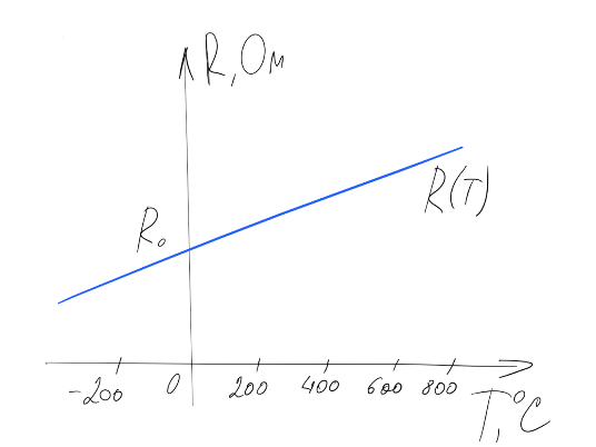
The dependence R (T), of course, is not absolutely linear - in fact, the output characteristic of the thermal resistance is described by a polynomial with known coefficients. In the simplest case, this is a second-degree polynomial R (T) = R0 (1 + A x T + B x T 2 ), where R0 is the nominal resistance of the sensor, that is, the resistance value at 0 ° C.
The type of polynomial and its coefficients are described in various national and international standards. The current Russian standard is GOST 6651-2009 . In Europe, DIN 60751 (also known as IEC-751) is used more often, but at the same time DIN 43760 is in effect, ASTM E1137 is popular in North America, and so on. Despite the fact that some of the standards are consistent, the overall picture is rather sad and there is no single industry standard.
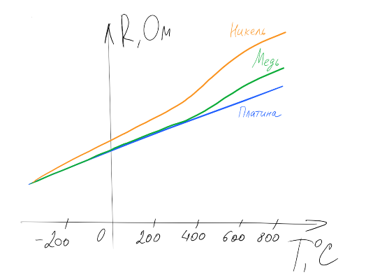
The most popular types of thermistors are platinum sensors (Pt 3850, Pt 3750, Pt 3911, etc.), nickel (Ni 6180, Ni 6720, etc.) and copper thermistors, for example Cu 4280. Each type of sensor has its own polynomial R (T ).
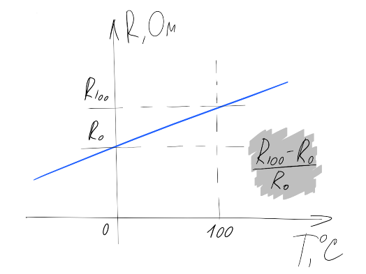
The above names contain the name of the metal used in the manufacture of the sensor, and the coefficient that describes the ratio of the resistance of the sensor at 0 to the resistance at 100 ° C. This coefficient, together with the value of R0, determines the slope of the function R (T).
In the diversified standards and, as a result, in the specifications for specific sensors, this coefficient can be expressed in different ways. For example, for a platinum sensor, an alpha coefficient of 0.00385 ° C -1 , or a temperature coefficient of 0.385% / ° C, or TCR = 3850 ppm / K can be specified, but in all three cases the same R (T) relationship is assumed.
The metal used uniquely determines the degree of the polynomial R (T), and the coefficients of the polynomial are determined by the temperature coefficient of the metal.
For example, for all platinum sensors, the R (T) function has the following form:
R (T) = R0 (1 + A x T + B x T 2 ) with T> 0
R (T) = R0 (1 + A x T + B x T 2 + C x (T-100) x T 3 ) with T <0
where the coefficients are selected depending on the type of platinum:
Pt 3770 ppm / K, Pt 3750 ppm / K, or Japanese Pt 3916 ppm / K will be matched by other coefficient sets.
The same logic applies to copper and nickel. For example, the NSH of all nickel sensors is described by a polynomial of the sixth degree:
R (T) = R0 (1 + A x T + B x T 2 + C x T 3 + D x T 4 + E x T 5 + F x T 6 )
where the coefficients are determined by the temperature coefficient of nickel (Ni 6180 ppm / K, Ni 6720 ppm / K, etc.).
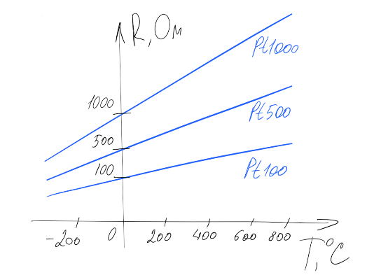
It remains to say about the last parameter NSH of resistance thermometers - the nominal resistance R0. The most commonly used sensors with standard R0 are 50, 100, 500 or 1000 Ohms, however, sometimes it is necessary to have a resistor with R0 = 2000 and even 10,000 Ohm, as well as sensors with a “non-multiple” nominal resistance.
That is, each type of thermal resistance can correspond to several NSH with different nominal resistances R0. For the most common characteristics in the Russian Federation, standard notations are used: Pt100 and Pt1000 correspond to platinum with a temperature coefficient of 3850 ppm / K and R0 = 100 and 1000 Ohms, respectively. The 50P and 100P designations inherited from the Soviet reference books are platinum sensors with a factor of 3911 ppm / K and R0 = 50 and 100 Ohms, and sensors known as 50 and 100 are 4280 ppm / K copper with a nominal resistance of 50 and 100 Ohms.
Sensor accuracy
The accuracy of thermal resistance is how much the dependence R (T) of a real sensor can deviate from the ideal NSH. To denote the accuracy of thermistors use the concept of tolerance class (from the accuracy class).
The tolerance class determines the maximum allowable deviation from the nominal characteristic, and this deviation is set as a function of temperature — at zero degrees, the smallest tolerance is fixed, and with decreasing or increasing temperature, the range of allowable values increases linearly.

When it comes to tolerance classes, the mess in existing standards is only getting worse - even class names in different sources may differ.
The tolerances given in the table correspond to most of the current standards for platinum sensors of 3850 ppm / K , including GOST and European DIN 60751 (IEC-751), which with a big stretch can be called generally accepted.
If we talk about platinum with other temperature coefficients or nickel and copper sensors, then you can find other definitions of tolerances.
The tolerance class describes not only the maximum tolerance, but also the temperature range over which this tolerance is guaranteed. You probably already guessed that in different standards, these ranges may differ significantly. This is true, and the temperature range depends not only on the tolerance class and type of sensor, but also on the technology used to make the sensor — for winding sensors, the range is always wider.
The picture shows the ticket for admission for platinum sensors with a temperature coefficient of 3850 according to DIN 60751 (IEC-751).

By the way, if in the documentation for thermal resistance the range of measured temperatures is specified, which is wider than the range provided for by the specified tolerance class, then the declared tolerance class will not apply over the entire operating range. For example, if a Pt1000 Class A sensor is designed to measure temperatures from -200 to + 600 ° C, then it will have an accuracy of ± (0.15 + 0.002 | T |) only at temperatures up to + 300 ° C, and then most likely the class will be provided AT.
I give all these details about the terminology and discrepancies in the standards in order to convey one simple idea: choosing a thermal resistance is easy to get confused and misinterpret the characteristics of an element. It is important to understand exactly what requirements you place on an element (in absolute figures, and not in classes) and compare them with absolute figures from the documentation for a specific sensor.
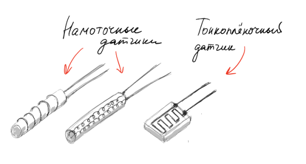
So, thermistors are resistors made of platinum or, more rarely, nickel or copper. We have already mentioned two technologies - winding (wire) and thin-film.
Winding sensors are thermistors made on the basis of metal wire spirals. There are two main methods of manufacturing winding sensors. In the first case, the wire is wound on a glass or ceramic cylinder, after which the structure is covered with an insulating layer of glass. The second method is to place metal spirals in the channels inside the ceramic cylinder.
In the manufacture of thin-film sensors, a thin layer of metal is deposited on the ceramic substrate, which forms a conductive path, the so-called meander. After that, the sensor is covered with an insulating glass layer.
Most modern thermistors are performed using one of these three technologies. In the sources there are conflicting opinions about which design is more resistant to vibrations or temperature extremes. Estimates of the cost of sensors of different designs also vary greatly.
In fact, there are no fundamental differences between the characteristics of sensors of different designs, the prices for thin-film and winding sensors are also in the same range.
In most cases, it doesn’t matter how the sensor works - when choosing a component, only the price-to-element ratio matters (you just have to remember that the tolerance classes for thin-film sensors are defined over a narrower temperature range). However, in some tasks, thin-film sensors consciously prefer winding. There are three main reasons for this:
There are other interesting properties of thin-film technology, which allow, for example, to reduce the response time of a temperature sensor or to produce flow velocity sensors on the basis of thermistors. We will talk about this in the next article, which is fully devoted to the process of manufacturing thin-film sensors.
In conclusion, I traditionally thank the reader for his attention and remind you that questions about the use of products, about which we write on Habré, can also be asked by email, specified in my profile.
upd # 1: The article Thermal Resistance: Production Process has been published .
upd # 2: all mentioned sensors and modules are available from stock. More information on efo-sensor.ru
On this occasion, I publish two articles in which the reader will find a rather detailed description of this type of sensors, a guide to the main stages of the production process and an overview of the possibilities that appear when using thin-film technologies.
')
In the first article we deal with the theoretical base. Not very exciting, but very useful.
What is resistance thermometers
(they are also thermistors or RTDs)First, it makes sense to understand the terminology. If you are familiar with the question, feel free to go to the second part of the article. And maybe immediately to the third.
So, under the definition of "temperature sensor" fall thousands of different products. The sensor can be understood as a ready-made measuring device, where the display shows the temperature value in degrees, and an integrated microcircuit with a digital signal at the output, and just a sensitive element, on the basis of which all other solutions are built. Today we are talking only about sensitive elements, which, however, will also be called the word "sensor".
Resistance thermometers, which are also known as RTDs and RTD (Resistance Temperature Detector), are sensitive elements whose principle of operation is well understood from the name - the electrical resistance of an element increases with increasing ambient temperature and vice versa. You have probably heard about thermistors as platinum temperature sensors such as Pt100, Pt500 and Pt1000 or 50M, 50P, 100M or 100P sensors.
Sometimes thermistors are confused with thermistors or thermocouples. All these sensors are used in similar tasks, but, despite the fact that thermistors are also temperature-resistance converters, thermistors and thermocouples should not be confused with each other. A thousand articles have already been written about the difference in the structure and purpose of these elements, so I’m probably not going to repeat.
I will note the main thing: the average resistance thermometer costs several times more than the average thermistor and thermocouple, but only thermal resistances have a linear output characteristic. The linearity of the characteristics, as well as the much higher rates of accuracy and repeatability of measurement results, make thermal resistances in demand despite the difference in price.
The main characteristics of thermistors
In short, the characteristics of thermistors can be divided into three groups:
- Nominal static characteristic (NSH) and accuracy
- The temperature range on which the NSH is determined and the declared accuracy is ensured
- Sensor body, pin type and length
In my opinion, only the first paragraph requires clarification.
Nominal static characteristic (NSH)
NSH is a function (in practice, more often a table of values), which determines the resistance-temperature relationship.
The dependence R (T), of course, is not absolutely linear - in fact, the output characteristic of the thermal resistance is described by a polynomial with known coefficients. In the simplest case, this is a second-degree polynomial R (T) = R0 (1 + A x T + B x T 2 ), where R0 is the nominal resistance of the sensor, that is, the resistance value at 0 ° C.
The type of polynomial and its coefficients are described in various national and international standards. The current Russian standard is GOST 6651-2009 . In Europe, DIN 60751 (also known as IEC-751) is used more often, but at the same time DIN 43760 is in effect, ASTM E1137 is popular in North America, and so on. Despite the fact that some of the standards are consistent, the overall picture is rather sad and there is no single industry standard.
The most popular types of thermistors are platinum sensors (Pt 3850, Pt 3750, Pt 3911, etc.), nickel (Ni 6180, Ni 6720, etc.) and copper thermistors, for example Cu 4280. Each type of sensor has its own polynomial R (T ).
The above names contain the name of the metal used in the manufacture of the sensor, and the coefficient that describes the ratio of the resistance of the sensor at 0 to the resistance at 100 ° C. This coefficient, together with the value of R0, determines the slope of the function R (T).
In the diversified standards and, as a result, in the specifications for specific sensors, this coefficient can be expressed in different ways. For example, for a platinum sensor, an alpha coefficient of 0.00385 ° C -1 , or a temperature coefficient of 0.385% / ° C, or TCR = 3850 ppm / K can be specified, but in all three cases the same R (T) relationship is assumed.
The metal used uniquely determines the degree of the polynomial R (T), and the coefficients of the polynomial are determined by the temperature coefficient of the metal.
For example, for all platinum sensors, the R (T) function has the following form:
R (T) = R0 (1 + A x T + B x T 2 ) with T> 0
R (T) = R0 (1 + A x T + B x T 2 + C x (T-100) x T 3 ) with T <0
where the coefficients are selected depending on the type of platinum:
- Pt 3850 ppm / K (the most common characteristic of modern thermistors)
A = 3.9083 x 10 -3 ° C -1
B = -5.775 x 10 -7 ° C -2
C = -4.183 x 10 -12 ° C -4 - Pt 3911 ppm / K (characteristic remains in demand in the Russian Federation, since in the past only it was included in GOST)
A = 3.9692 x 10 -3 ° C -1
B = -5.829 x 10 -7 ° C -2
C = -4.3303 x 10 -12 ° C -4
Pt 3770 ppm / K, Pt 3750 ppm / K, or Japanese Pt 3916 ppm / K will be matched by other coefficient sets.
The same logic applies to copper and nickel. For example, the NSH of all nickel sensors is described by a polynomial of the sixth degree:
R (T) = R0 (1 + A x T + B x T 2 + C x T 3 + D x T 4 + E x T 5 + F x T 6 )
where the coefficients are determined by the temperature coefficient of nickel (Ni 6180 ppm / K, Ni 6720 ppm / K, etc.).
It remains to say about the last parameter NSH of resistance thermometers - the nominal resistance R0. The most commonly used sensors with standard R0 are 50, 100, 500 or 1000 Ohms, however, sometimes it is necessary to have a resistor with R0 = 2000 and even 10,000 Ohm, as well as sensors with a “non-multiple” nominal resistance.
That is, each type of thermal resistance can correspond to several NSH with different nominal resistances R0. For the most common characteristics in the Russian Federation, standard notations are used: Pt100 and Pt1000 correspond to platinum with a temperature coefficient of 3850 ppm / K and R0 = 100 and 1000 Ohms, respectively. The 50P and 100P designations inherited from the Soviet reference books are platinum sensors with a factor of 3911 ppm / K and R0 = 50 and 100 Ohms, and sensors known as 50 and 100 are 4280 ppm / K copper with a nominal resistance of 50 and 100 Ohms.
Sensor accuracy
The accuracy of thermal resistance is how much the dependence R (T) of a real sensor can deviate from the ideal NSH. To denote the accuracy of thermistors use the concept of tolerance class (from the accuracy class).
The tolerance class determines the maximum allowable deviation from the nominal characteristic, and this deviation is set as a function of temperature — at zero degrees, the smallest tolerance is fixed, and with decreasing or increasing temperature, the range of allowable values increases linearly.
When it comes to tolerance classes, the mess in existing standards is only getting worse - even class names in different sources may differ.
| Other names | Tolerance, ° | |
| Class AA | Class y 1/3 DIN 1/3 B F 0.1 (if talking about thin-film sensor) W 0.1 (if we are talking about a winding sensor) | ± (0.1 + 0.0017 | T |) |
| Class A | 1/2 DIN 1/2 B F 0.15 (if talking about thin-film sensor) W 0.15 (if it is a winding sensor) | ± (0.15 + 0.002 | T |) |
| Class B | DIN F 0.3 (if talking about thin-film sensor) W 0.3 (if it is a winding sensor) | ± (0.3 + 0.005 | T |) |
| Class C | Class 2B Class BB F 0.6 (if talking about thin-film sensor) W 0.6 (if we are talking about a winding sensor) | ± (0.6 + 0.01 | T |) |
| - | Class k 1/10 DIN | ± (0.03 + 0.0005 | T |) |
| - | Class k 1/5 DIN | ± (0.06 + 0.001 | T |) |
The tolerances given in the table correspond to most of the current standards for platinum sensors of 3850 ppm / K , including GOST and European DIN 60751 (IEC-751), which with a big stretch can be called generally accepted.
However, there are exceptions.
For example, in the American standard ASTM E1137, the tolerance classes for platinum sensors are called Grade and are defined differently:
| Grad a | ± (0.25 + 0.0042 | T |) |
| Grad b | ± (0.13 + 0.0017 | T |) |
If we talk about platinum with other temperature coefficients or nickel and copper sensors, then you can find other definitions of tolerances.
The tolerance class describes not only the maximum tolerance, but also the temperature range over which this tolerance is guaranteed. You probably already guessed that in different standards, these ranges may differ significantly. This is true, and the temperature range depends not only on the tolerance class and type of sensor, but also on the technology used to make the sensor — for winding sensors, the range is always wider.
On what winding and thin-film sensors - just below.
The picture shows the ticket for admission for platinum sensors with a temperature coefficient of 3850 according to DIN 60751 (IEC-751).
Tolerance class definitions for thin film and winding platinum sensors Pt 3850 ppm / K
| Pt 3850 ppm / K thin film sensor | Pt 3850 ppm / K winding sensor | ||||
| Tolerance class | Temperature range | Tolerance class | Temperature range | ||
| DIN 60751 (IEC-751) / GOST | DIN 60751 (IEC-751) | GOST | |||
| AA class (F 0.1) | 0 ... + 150 ° | AA class (W 0.1) | -100 ... + 350 ° | -50 ... + 250 ° | |
| Class A (F 0.15) | -30 ... + 300 ° | Class A (W 0.15) | -100 ... + 450 ° | ||
| Class B (F 0.3) | -50 ... + 500 ° | Class B (W 0.3) | -196 ... + 600 ° | -196 ... + 660 ° | |
| Class C (F 0.6) | -50 ... + 600 ° | Class C (W 0.6) | -196 ... + 600 ° | -196 ... + 660 ° | |
By the way, if in the documentation for thermal resistance the range of measured temperatures is specified, which is wider than the range provided for by the specified tolerance class, then the declared tolerance class will not apply over the entire operating range. For example, if a Pt1000 Class A sensor is designed to measure temperatures from -200 to + 600 ° C, then it will have an accuracy of ± (0.15 + 0.002 | T |) only at temperatures up to + 300 ° C, and then most likely the class will be provided AT.
I give all these details about the terminology and discrepancies in the standards in order to convey one simple idea: choosing a thermal resistance is easy to get confused and misinterpret the characteristics of an element. It is important to understand exactly what requirements you place on an element (in absolute figures, and not in classes) and compare them with absolute figures from the documentation for a specific sensor.
The structure of resistance thermometers
So, thermistors are resistors made of platinum or, more rarely, nickel or copper. We have already mentioned two technologies - winding (wire) and thin-film.
Winding sensors are thermistors made on the basis of metal wire spirals. There are two main methods of manufacturing winding sensors. In the first case, the wire is wound on a glass or ceramic cylinder, after which the structure is covered with an insulating layer of glass. The second method is to place metal spirals in the channels inside the ceramic cylinder.
In the manufacture of thin-film sensors, a thin layer of metal is deposited on the ceramic substrate, which forms a conductive path, the so-called meander. After that, the sensor is covered with an insulating glass layer.
Most modern thermistors are performed using one of these three technologies. In the sources there are conflicting opinions about which design is more resistant to vibrations or temperature extremes. Estimates of the cost of sensors of different designs also vary greatly.
In fact, there are no fundamental differences between the characteristics of sensors of different designs, the prices for thin-film and winding sensors are also in the same range.
In most cases, it doesn’t matter how the sensor works - when choosing a component, only the price-to-element ratio matters (you just have to remember that the tolerance classes for thin-film sensors are defined over a narrower temperature range). However, in some tasks, thin-film sensors consciously prefer winding. There are three main reasons for this:
- High nominal resistance. Thin-film technology allows sensors with R0 = 1000 Ohms to be produced at the same price as sensors with a nominal resistance of 50, 100 or 500 Ohms. In addition, sensors are manufactured with a higher nominal resistance, for example, 2000 and 10000 ohms.
- Small size. Thin-film sensor can be made much smaller than winding. A standard Pt1000 sensor, for example, can have dimensions of only 1.6 x 1.2 mm.
- The rectangular shape and the miniature size of the film sensors make it possible to produce not only the output thermal resistances, but also SMD components of standard sizes - 1206, 0805, and so on.
There are other interesting properties of thin-film technology, which allow, for example, to reduce the response time of a temperature sensor or to produce flow velocity sensors on the basis of thermistors. We will talk about this in the next article, which is fully devoted to the process of manufacturing thin-film sensors.
Conclusion
In conclusion, I traditionally thank the reader for his attention and remind you that questions about the use of products, about which we write on Habré, can also be asked by email, specified in my profile.
upd # 1: The article Thermal Resistance: Production Process has been published .
upd # 2: all mentioned sensors and modules are available from stock. More information on efo-sensor.ru
Source: https://habr.com/ru/post/312898/
All Articles