Getting started in STM32CubeMX. Part 2
Part 1
Part 3
Last time, we learned how to create a new project in STM32CubeMX, set up a clock generator, a timer and an I / O port, and a little bit flashed the LED. Today we will master the digital-to-analog converter and learn how to work with it through DMA. As a result, we should have a simple direct synthesis (Direct digital synthesizer, DDS) generator.
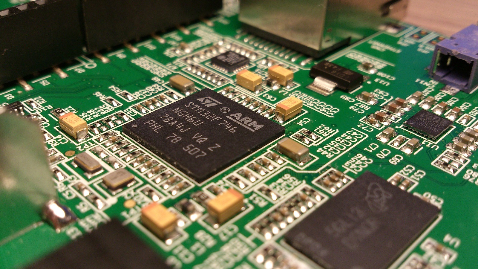
Most of the STM32 microcontrollers are equipped with 12-bit DAC in the amount of one or two pieces. The DAC architecture is the same in all crystals, no matter which core ARM Cortex M is used there. Thus, today's experiment can be performed on any STM32 microcontroller with at least one DAC.
')
What is the frequency of DAC conversion? The answer to this question is not quite simple. If you want more details, I recommend these two documents: [1] [2]
To summarize, it is as follows: the DAC itself can update the output with a frequency of up to 5 MSPS (mega-samples per second), but the buffer operational amplifier (OU) at the output will not provide this speed, limiting it to 1 MSPS. If we want more, we need an external op-amp, to which some requirements are imposed on the frequency characteristics, which will be discussed below. It is impossible to use the buffer DU DAC, since it has a rather large output impedance (> 10 kΩ).
At a frequency higher than a hundred kilohertz, the built-in buffer amplifier begins to introduce significant distortions into the signal, so I immediately put an external buffer amplifier at the output that satisfies ST recommendations.
To achieve a 5MSPS conversion rate, ST recommends using an OU with a unit amplification frequency of at least 10 MHz, a gain with open-loop feedback of at least 60 dB, and an slew rate of output of at least 16.5 V / μs. ST recommends as an example the Shelter LMH6645 / 6646/6647 manufactured by Texas Instruments.
I used the AD845JN opamp, which has a single gain frequency of 16 MHz, a typical gain value of 500 V / mV (about 114 dB) and a slew rate of 100 V / μs. Power is supplied from the DC / DC converter 5 V / ± 9 B. You can power the buffer amplifier with unipolar power, for example, by taking 5 V directly from the board, but then you will need a rail-to-rail amplifier. Connection diagram is shown in Fig. one.

Fig. 1. Diagram of the output buffer amplifier
I didn’t do a special board, I mounted it with a wire on a breadboard board, which is inserted into an arduino-compatible footprint for debugging.

Fig. 2. View of the buffer amplifier board
The internal buffer amplifier of the microcontroller begins to introduce noticeable non-linear distortions already starting at a frequency of 100-150 kHz. If you are not going to use the DAC to generate signals above these frequencies, you can do without a buffer.
Now go to the software part.
We will assume that we are already able to create a project in CubeMX, choose a microcontroller and adjust the clock generator, as in the first part. You can simply take the project from the first part and continue it.
On the board I use, the DAC outputs are not very conveniently output, unfortunately, DAC_OUT1 (pin N4) is connected to the DCMI connector, DAC_OUT2 (pin P4) is connected to the USB interface and can hardly be used as a DAC output. Therefore, only DAC_OUT1 remains. Enable it in the Pinout tab:

In the Configuration tab, the DAC has only one interesting setting for us: Output Buffer. If you do not use an external amplifier, it must be turned on; if you use it, it is turned off.
You can control the output of the DAC "manually" from the program, you can use DMA. The second method is well suited for generating a periodic signal of an arbitrary shape, and we will look at it below, and now we are using the first method. Just set the output voltage uninteresting, try to generate a signal. For this we need a timer. We do everything as in the first part, only the frequency of the timer is set more, for example, 500 kHz. To do this, set Prescaler = 215, then we get 216 MHz / (215 + 1) = 1 MHz, and Counter Period = 1, which will give 1 MHz / (1 + 1) = 500 kHz. I remind you that 216 MHz is the peripheral clocking frequency in our clocking system configuration.
We generate the code, open the project and enter the following:
Once again I remind you that all user code is written between lines of the form / * USER CODE BEGIN ... * / ... / * USER CODE END ... * /
The first piece of code is the timer interrupt handler, in which 0 and 4095 are written alternately in the DAC register, that is, the minimum and maximum DAC values. The second section of the code includes a timer and DAC. We obtain rectangular oscillations with a frequency of 250 kHz, but due to the distortions introduced by the buffer amplifier, they look like this:

It's time to use the external buffer, disabling the internal one. To do this, go to the Configuration tab in STM32CubeMX, click the DAC button, and on the Parameter Settings tab, set Output Buffer = Disable. Re-generate the code and flash into the board. Now the pulses look like a meander passed through the low-pass filter (due to the fact that the system bandwidth is still limited):

You can even approximately estimate the cutoff frequency of the low pass filter.

The method is clear from the figure: draw a tangent to the exponent until the intersection with the upper signal level. The distance on the time scale from the beginning of the pulse to the intersection will be the filter time constant τ = 400 ns, the cutoff frequency is fc = 1 / 2πτ ≈ 0.4 MHz.
Let's try to double the frequency, reducing the Prescaler to 107, but disappointment awaits us: the frequency does not rise above 333 kHz. Probably need some code optimization.
In fact, the greatest delay is introduced by the huge timer interrupt handler in the depths of the HAL (HAL_TIM_IRQHandler function). You can replace it with your own. To do this, find the file stm32f7xx_it, and in it we change the function TIM1_UP_TIM10_IRQHandler:
HAL_TIM_IRQHandler is no longer called. Now the timer frequency can be raised to 2 MHz, and the frequency of the meander, respectively, to 1 MHz. To do this, in the timer settings, set the value to Prescaler = 53, and then we get the following picture:

This is probably the maximum frequency achievable on this microcontroller.
The HAL library is, of course, a handy thing, but inside it there are many different actions that can be avoided. It should just be remembered that premature optimization is evil, and resorting to it only when we have reached the limit, like this time.
Another nuance. We can notice that sometimes strange jumps with a period of 1ms occur in the signal.

They are obtained as a result of the fact that we have another interrupt in the system, which has a higher priority than our timer. It is hidden inside the HAL, and this is the SysTick system timer, which has the highest (zero) interrupt priority. To correct the situation, go to STM32CubeMX-> Configuration-> NVIC-> Time base: System Tick Timer-> Preeption Priority = 1. Re-generate the code, the signal distortions have disappeared.
Let's try to generate a sinusoidal signal. For this, we need an array of N values, filled with the values of the round (A * cos ((pi / 2) * (n / N))) function, where A is the signal amplitude, N is the number of points in the array, n is the point number. During the output, we shift the points by shift = 2048, let the amplitude be A = 2047, then the DAC values will be from 1 to 4095. The array can be filled only for a quarter of the period, from 0 to pi / 2, and the missing values will be obtained from it by obvious arithmetic action. Why use the cosine function, not the sine, I will write further.
How to choose N? On the one hand, the more N, the better, the values will be closer to the exact values, on the other hand, the limited DAC capacity makes such an increase useless after the value [A * pi / 2] = 3215. In fact, with N = 3215 the increment of the angle will be pi / (2 * 3215) = 4.89e-4, and the increment of the amplitude near the middle of the scale, where the growth rate is maximum, will be 4.89e-4 * 2047 = 1 discrete DAC.
We can generate an array in advance and place it in flash-memory, we can generate it at run-time during initialization. The first method is preferable for practical use, but we will use the second for greater clarity:
I want the array and signal conditioning to occur in main, so we change the interrupt handler code in the stm32f7xx_it file to the following:
Now the “slow” function HAL_TIM_IRQHandler () is not called, but HAL_TIM_PeriodElapsedCallback is called in main. In the main write the following:
This code also contains the delta value, the phase increment. By changing the delta, you can change the frequency of the signal over a wide range. delta = 1 corresponds to the lowest frequency (and the best approximation of the sinusoidal function), the maximum value of delta, which makes sense in this case is 2 * N. In this case, the output should be a meander, because the phase alternately becomes 0, then pi, and the cosine values are 1 and -1, respectively. Therefore, we wrote down the cosine instead of sine into the array; with a sine, the function values at these points would be 0, and we would not see any signal.
In STM32CubeMX, we set the frequency of the 500 kHz timer operation, like this: Prescaler = 107, Counter Period = 3. We get a beautiful sinusoid with a frequency of 500e3 / (4 * 3216) = 38.868 Hz.

The maximum frequency at these settings will be 250 kHz. In this case, the signal will turn into a meander, we have already seen them. Let's try to get 10 kHz. To do this, we need to set delta - (1e4 / 2e5) * 4 * 3216 = 257.28. Rounded to an integer value of 257, we obtain the calculated value of the frequency (5e3 * 257) / (4 * 3216) = 9989 Hz. We get this picture:

The difference with a frequency of 10 kHz is about 0.1%. Is it possible to set the frequency more accurately? It is possible, but for this you need to consider the phase as a float, but at this sampling rate (500 kHz) the microcontroller does not have time to count the phase as a float. It is possible to reduce the clock frequency of the timer or try to manually optimize the code, but this is another story. So far, the achieved accuracy suits us.
The digital-to-analog converter (DAC) built into the STM32 microcontrollers can operate on timer signals and receive data directly from the memory array via DMA. Thus, it is possible to configure the controller so that the DAC will work without the participation of the program, without wasting CPU resources, with the exception of system initialization.
The disadvantage of the DMA method is that tricks with writing to a quarter-period array and calculating phase accumulation are impossible here. We have to write the entire array into memory and specify the desired period. The advantage, as already mentioned, is that when generating a signal through a DMA processor is free for other work.
So, we will open a new project in STM32CubeMX, and we will do the procedure of configuration of a clock generator already familiar to us. Now we set up the rest.
DMA can call two timers: TIM6 and TIM7. Enable TIM6.

Next, set the following settings:


We generate the code, and paste the following into main:
Of course, we can make an array of a different size. The size of the array should be passed to the HAL_DAC_Start_DMA function by the fourth parameter, after the array address.
After launching the program, we should get a sine wave at the output, exactly the same as mentioned above, so I will not give a screenshot.
That's all I wanted to write about working with the DAC.
Next time we will briefly discuss the operation of the ADC and the USB interface.
1. AN3126
Application note "Audio and waveform generation using the DAC in STM32 microcontrollers"
2. AN4566
Application note "Extending the DAC performance of STM32 microcontrollers"
The examples given in the article were also implemented on the Nucleo F767ZI (microcontroller STM32F767ZI) board, in IDE Atollic TrueStudio. They can be downloaded here: https://github.com/arktur04/stm32-habr
Part 3
Last time, we learned how to create a new project in STM32CubeMX, set up a clock generator, a timer and an I / O port, and a little bit flashed the LED. Today we will master the digital-to-analog converter and learn how to work with it through DMA. As a result, we should have a simple direct synthesis (Direct digital synthesizer, DDS) generator.
Work with DAC
Most of the STM32 microcontrollers are equipped with 12-bit DAC in the amount of one or two pieces. The DAC architecture is the same in all crystals, no matter which core ARM Cortex M is used there. Thus, today's experiment can be performed on any STM32 microcontroller with at least one DAC.
')
What is the frequency of DAC conversion? The answer to this question is not quite simple. If you want more details, I recommend these two documents: [1] [2]
To summarize, it is as follows: the DAC itself can update the output with a frequency of up to 5 MSPS (mega-samples per second), but the buffer operational amplifier (OU) at the output will not provide this speed, limiting it to 1 MSPS. If we want more, we need an external op-amp, to which some requirements are imposed on the frequency characteristics, which will be discussed below. It is impossible to use the buffer DU DAC, since it has a rather large output impedance (> 10 kΩ).
Some circuitry
At a frequency higher than a hundred kilohertz, the built-in buffer amplifier begins to introduce significant distortions into the signal, so I immediately put an external buffer amplifier at the output that satisfies ST recommendations.
To achieve a 5MSPS conversion rate, ST recommends using an OU with a unit amplification frequency of at least 10 MHz, a gain with open-loop feedback of at least 60 dB, and an slew rate of output of at least 16.5 V / μs. ST recommends as an example the Shelter LMH6645 / 6646/6647 manufactured by Texas Instruments.
I used the AD845JN opamp, which has a single gain frequency of 16 MHz, a typical gain value of 500 V / mV (about 114 dB) and a slew rate of 100 V / μs. Power is supplied from the DC / DC converter 5 V / ± 9 B. You can power the buffer amplifier with unipolar power, for example, by taking 5 V directly from the board, but then you will need a rail-to-rail amplifier. Connection diagram is shown in Fig. one.
Fig. 1. Diagram of the output buffer amplifier
I didn’t do a special board, I mounted it with a wire on a breadboard board, which is inserted into an arduino-compatible footprint for debugging.
Fig. 2. View of the buffer amplifier board
The internal buffer amplifier of the microcontroller begins to introduce noticeable non-linear distortions already starting at a frequency of 100-150 kHz. If you are not going to use the DAC to generate signals above these frequencies, you can do without a buffer.
Now go to the software part.
DAC configuration
We will assume that we are already able to create a project in CubeMX, choose a microcontroller and adjust the clock generator, as in the first part. You can simply take the project from the first part and continue it.
On the board I use, the DAC outputs are not very conveniently output, unfortunately, DAC_OUT1 (pin N4) is connected to the DCMI connector, DAC_OUT2 (pin P4) is connected to the USB interface and can hardly be used as a DAC output. Therefore, only DAC_OUT1 remains. Enable it in the Pinout tab:
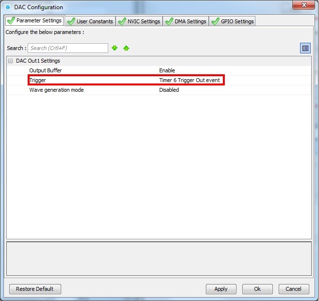
In the Configuration tab, the DAC has only one interesting setting for us: Output Buffer. If you do not use an external amplifier, it must be turned on; if you use it, it is turned off.
You can control the output of the DAC "manually" from the program, you can use DMA. The second method is well suited for generating a periodic signal of an arbitrary shape, and we will look at it below, and now we are using the first method. Just set the output voltage uninteresting, try to generate a signal. For this we need a timer. We do everything as in the first part, only the frequency of the timer is set more, for example, 500 kHz. To do this, set Prescaler = 215, then we get 216 MHz / (215 + 1) = 1 MHz, and Counter Period = 1, which will give 1 MHz / (1 + 1) = 500 kHz. I remind you that 216 MHz is the peripheral clocking frequency in our clocking system configuration.
Signal generation from interrupt handler
We generate the code, open the project and enter the following:
/* USER CODE BEGIN 0 */ void HAL_TIM_PeriodElapsedCallback(TIM_HandleTypeDef *htim) { static int val = 0; if (htim->Instance==TIM1) //check if the interrupt comes from TIM1 { HAL_DAC_SetValue(&hdac, DAC_CHANNEL_1, DAC_ALIGN_12B_R, val); val = val? 0: 4095; } } /* USER CODE END 0 */ ... /* USER CODE BEGIN 2 */ HAL_TIM_Base_Start_IT(&htim1); __HAL_DAC_ENABLE(&hdac, DAC_CHANNEL_1); /* USER CODE END 2 */ Once again I remind you that all user code is written between lines of the form / * USER CODE BEGIN ... * / ... / * USER CODE END ... * /
The first piece of code is the timer interrupt handler, in which 0 and 4095 are written alternately in the DAC register, that is, the minimum and maximum DAC values. The second section of the code includes a timer and DAC. We obtain rectangular oscillations with a frequency of 250 kHz, but due to the distortions introduced by the buffer amplifier, they look like this:
It's time to use the external buffer, disabling the internal one. To do this, go to the Configuration tab in STM32CubeMX, click the DAC button, and on the Parameter Settings tab, set Output Buffer = Disable. Re-generate the code and flash into the board. Now the pulses look like a meander passed through the low-pass filter (due to the fact that the system bandwidth is still limited):
You can even approximately estimate the cutoff frequency of the low pass filter.
The method is clear from the figure: draw a tangent to the exponent until the intersection with the upper signal level. The distance on the time scale from the beginning of the pulse to the intersection will be the filter time constant τ = 400 ns, the cutoff frequency is fc = 1 / 2πτ ≈ 0.4 MHz.
Let's try to double the frequency, reducing the Prescaler to 107, but disappointment awaits us: the frequency does not rise above 333 kHz. Probably need some code optimization.
In fact, the greatest delay is introduced by the huge timer interrupt handler in the depths of the HAL (HAL_TIM_IRQHandler function). You can replace it with your own. To do this, find the file stm32f7xx_it, and in it we change the function TIM1_UP_TIM10_IRQHandler:
void TIM1_UP_TIM10_IRQHandler(void) { /* USER CODE BEGIN TIM1_UP_TIM10_IRQn 0 */ static int val = 0; /* TIM Update event */ __HAL_TIM_CLEAR_IT(&htim1, TIM_IT_UPDATE); if (htim1.Instance==TIM1) { *(uint32_t*)(DAC_BASE + 0x00000008U) = val; val = val? 0: 4095; } return; /* USER CODE END TIM1_UP_TIM10_IRQn 0 */ HAL_TIM_IRQHandler(&htim1); /* USER CODE BEGIN TIM1_UP_TIM10_IRQn 1 */ /* USER CODE END TIM1_UP_TIM10_IRQn 1 */ } HAL_TIM_IRQHandler is no longer called. Now the timer frequency can be raised to 2 MHz, and the frequency of the meander, respectively, to 1 MHz. To do this, in the timer settings, set the value to Prescaler = 53, and then we get the following picture:
This is probably the maximum frequency achievable on this microcontroller.
The HAL library is, of course, a handy thing, but inside it there are many different actions that can be avoided. It should just be remembered that premature optimization is evil, and resorting to it only when we have reached the limit, like this time.
Another nuance. We can notice that sometimes strange jumps with a period of 1ms occur in the signal.
They are obtained as a result of the fact that we have another interrupt in the system, which has a higher priority than our timer. It is hidden inside the HAL, and this is the SysTick system timer, which has the highest (zero) interrupt priority. To correct the situation, go to STM32CubeMX-> Configuration-> NVIC-> Time base: System Tick Timer-> Preeption Priority = 1. Re-generate the code, the signal distortions have disappeared.
Let's try to generate a sinusoidal signal. For this, we need an array of N values, filled with the values of the round (A * cos ((pi / 2) * (n / N))) function, where A is the signal amplitude, N is the number of points in the array, n is the point number. During the output, we shift the points by shift = 2048, let the amplitude be A = 2047, then the DAC values will be from 1 to 4095. The array can be filled only for a quarter of the period, from 0 to pi / 2, and the missing values will be obtained from it by obvious arithmetic action. Why use the cosine function, not the sine, I will write further.
How to choose N? On the one hand, the more N, the better, the values will be closer to the exact values, on the other hand, the limited DAC capacity makes such an increase useless after the value [A * pi / 2] = 3215. In fact, with N = 3215 the increment of the angle will be pi / (2 * 3215) = 4.89e-4, and the increment of the amplitude near the middle of the scale, where the growth rate is maximum, will be 4.89e-4 * 2047 = 1 discrete DAC.
We can generate an array in advance and place it in flash-memory, we can generate it at run-time during initialization. The first method is preferable for practical use, but we will use the second for greater clarity:
I want the array and signal conditioning to occur in main, so we change the interrupt handler code in the stm32f7xx_it file to the following:
void TIM1_UP_TIM10_IRQHandler(void) { /* USER CODE BEGIN TIM1_UP_TIM10_IRQn 0 */ /* TIM Update event */ if(__HAL_TIM_GET_FLAG(&htim1, TIM_FLAG_UPDATE) != RESET) { if(__HAL_TIM_GET_IT_SOURCE(&htim1, TIM_IT_UPDATE) !=RESET) { __HAL_TIM_CLEAR_IT(&htim1, TIM_IT_UPDATE); if (htim1.Instance==TIM1) { HAL_TIM_PeriodElapsedCallback(&htim1); } } } return; /* USER CODE END TIM1_UP_TIM10_IRQn 0 */ HAL_TIM_IRQHandler(&htim1); /* USER CODE BEGIN TIM1_UP_TIM10_IRQn 1 */ /* USER CODE END TIM1_UP_TIM10_IRQn 1 */ } Now the “slow” function HAL_TIM_IRQHandler () is not called, but HAL_TIM_PeriodElapsedCallback is called in main. In the main write the following:
/* USER CODE BEGIN Includes */ #include "math.h" /* USER CODE END Includes */ /* USER CODE BEGIN 0 */ volatile uint32_t * dac; #define N 3216 #define DAC_SHIFT 2047 static uint16_t cosine[N]; const int delta = 1; void HAL_TIM_PeriodElapsedCallback(TIM_HandleTypeDef *htim) { static int val = 0; static int phase = 0; *(uint32_t*)(DAC_BASE + 0x00000008U) = val; phase += delta; phase = phase > N * 4 - 1 ? phase - N * 4 : phase; if(phase < N) { val = DAC_SHIFT + cosine[phase]; } else if(phase < 2 * N) { val = DAC_SHIFT - cosine[2 * N - 1 - phase]; } else if(phase < 3 * N) { val = DAC_SHIFT - cosine[phase - 2 * N]; } else { val = DAC_SHIFT + cosine[4 * N - 1 - phase]; } } /* USER CODE END 0 */ int main(void) { /* USER CODE BEGIN 2 */ const float A = 2047; const float PI = 3.1415927; for(int i = 0; i < N; i++) { cosine[i] = (uint16_t)(round(A * cos((i * PI) / (N * 2.0)))); } HAL_TIM_Base_Start_IT(&htim1); __HAL_DAC_ENABLE(&hdac, DAC_CHANNEL_1); /* USER CODE END 2 */ This code also contains the delta value, the phase increment. By changing the delta, you can change the frequency of the signal over a wide range. delta = 1 corresponds to the lowest frequency (and the best approximation of the sinusoidal function), the maximum value of delta, which makes sense in this case is 2 * N. In this case, the output should be a meander, because the phase alternately becomes 0, then pi, and the cosine values are 1 and -1, respectively. Therefore, we wrote down the cosine instead of sine into the array; with a sine, the function values at these points would be 0, and we would not see any signal.
In STM32CubeMX, we set the frequency of the 500 kHz timer operation, like this: Prescaler = 107, Counter Period = 3. We get a beautiful sinusoid with a frequency of 500e3 / (4 * 3216) = 38.868 Hz.
The maximum frequency at these settings will be 250 kHz. In this case, the signal will turn into a meander, we have already seen them. Let's try to get 10 kHz. To do this, we need to set delta - (1e4 / 2e5) * 4 * 3216 = 257.28. Rounded to an integer value of 257, we obtain the calculated value of the frequency (5e3 * 257) / (4 * 3216) = 9989 Hz. We get this picture:
The difference with a frequency of 10 kHz is about 0.1%. Is it possible to set the frequency more accurately? It is possible, but for this you need to consider the phase as a float, but at this sampling rate (500 kHz) the microcontroller does not have time to count the phase as a float. It is possible to reduce the clock frequency of the timer or try to manually optimize the code, but this is another story. So far, the achieved accuracy suits us.
Work with DMA
The digital-to-analog converter (DAC) built into the STM32 microcontrollers can operate on timer signals and receive data directly from the memory array via DMA. Thus, it is possible to configure the controller so that the DAC will work without the participation of the program, without wasting CPU resources, with the exception of system initialization.
The disadvantage of the DMA method is that tricks with writing to a quarter-period array and calculating phase accumulation are impossible here. We have to write the entire array into memory and specify the desired period. The advantage, as already mentioned, is that when generating a signal through a DMA processor is free for other work.
So, we will open a new project in STM32CubeMX, and we will do the procedure of configuration of a clock generator already familiar to us. Now we set up the rest.
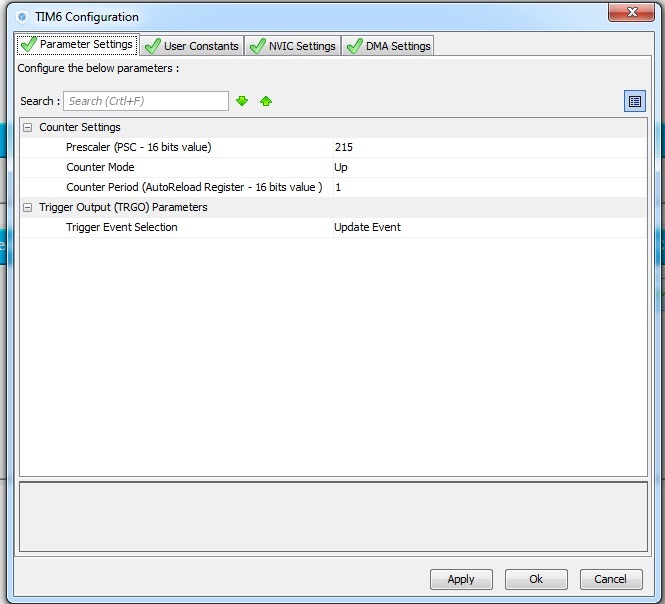
DMA can call two timers: TIM6 and TIM7. Enable TIM6.
Next, set the following settings:
We generate the code, and paste the following into main:
/* USER CODE BEGIN Includes */ #include "math.h" /* USER CODE END Includes */ //... /* USER CODE BEGIN 0 */ #define N 3216 static uint16_t sine[N * 4]; /* USER CODE END 0 */ int main(void) { /* USER CODE BEGIN 1 */ /* USER CODE END 1 */ /* MCU Configuration----------------------------------------------------------*/ /* Reset of all peripherals, Initializes the Flash interface and the Systick. */ HAL_Init(); /* Configure the system clock */ SystemClock_Config(); /* Initialize all configured peripherals */ MX_GPIO_Init(); MX_DMA_Init(); MX_TIM6_Init(); MX_DAC_Init(); /* USER CODE BEGIN 2 */ const float A = 2047; const float PI = 3.1415927; for(int i = 0; i < N * 4; i++) { sine[i] = 2048 + (int16_t)(round(A * sin((i * PI) / (N * 2.0)))); } HAL_TIM_Base_Start(&htim6); HAL_DAC_Start(&hdac,DAC_CHANNEL_1); HAL_DAC_Start_DMA(&hdac, DAC_CHANNEL_1, (uint32_t*)sine, N * 4, DAC_ALIGN_12B_R); /* USER CODE END 2 */ Of course, we can make an array of a different size. The size of the array should be passed to the HAL_DAC_Start_DMA function by the fourth parameter, after the array address.
After launching the program, we should get a sine wave at the output, exactly the same as mentioned above, so I will not give a screenshot.
That's all I wanted to write about working with the DAC.
What's next?
Next time we will briefly discuss the operation of the ADC and the USB interface.
1. AN3126
Application note "Audio and waveform generation using the DAC in STM32 microcontrollers"
2. AN4566
Application note "Extending the DAC performance of STM32 microcontrollers"
PS
The examples given in the article were also implemented on the Nucleo F767ZI (microcontroller STM32F767ZI) board, in IDE Atollic TrueStudio. They can be downloaded here: https://github.com/arktur04/stm32-habr
Source: https://habr.com/ru/post/312810/
All Articles