How to love mbed, and then screw it up twice
This article ends the cycle of publications about the development of the measuring device in the online IDE mbed from the company ARM.
Actually, the story of the development of software for microcontrollers and the used hardware blocks have already been completed, as many as five articles turned out. But I love whole stories, so I’ll tell you how everything was ruined when I tried to put the developed system into the case. Twice.
Previous articles:
Well, well, it's not that everything is completely spoiled, but the mistakes happened quite funny.
')
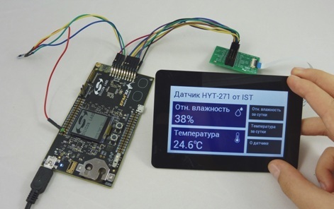
We do not develop electronics, we supply electronic components. The device was conceived and implemented solely to demonstrate the operation of two hardware units - a beautiful capacitive TFT display from Riverdi and a HYT series relative humidity sensor from IST-AG.
That is, the plans have never been to release something similar in series, or even to do the second such device. Therefore, and also because the device should be easily disassembled into parts, we enclose not a specially made compact printed circuit board, but just a few debugs from the manufacturer - with unused hardware blocks, connections from the design wires and the rest of disgrace.
After consulting with colleagues involved in the supply and refinement of cases for electronic equipment, it was decided to take the back and leg from the standard OKW case, and print the front wall on their own. In addition to it, the “internal” parts were printed on the 3D printer — a small camera for installing the HY-271 sensor and parts for fixing the boards inside the case.
When creating a model for printing using SolidWorks and Polygon. The printer uses today's most popular technology - Fusing Deposition Modeling (FDM).
Printing is not at all my profile, so I’ll only say common words.
The essence of the technology of layer-by-layer welding is reflected in its name. After creating a three-dimensional model of the part and downloading this model to the printer, layer-by-layer application of hot plastic begins, which freezes immediately after the application of the next layer. Unlike other 3D printing technologies, an extruder is a moving element in FDM — a nozzle on which plastic melts and is squeezed onto a model.
The disadvantages of this printing technology are shrinking and low print resolution. Shrinking can affect (and affects) the size of the final product, and low print resolution causes a layered surface that is noticeable to the naked eye. However, these shortcomings are more than compensated by the low price of equipment and materials for layered printing, which is why in recent years we have heard about 3D printing from each iron.
Layered printing is great for creating piece products and prototypes for mass production. In my case, the print quality was enough for parts that fit inside the case, but the surface of the front cover of the case had to be refined - polished, polished, finishedand even slightly heated with a blowtorch . For a couple of hours, it was possible to make the layers of plastic on the surface of the lid almost imperceptible.
Let's proceed to the assembly. Let me remind you that the project uses the HYT-271 sensor - a model of a relative humidity sensor, made without a protective metal case. It was decided to place the sensor in a small chamber without a front wall, and attach this chamber to the front cover of the case, where rather large openings are provided for contact of the sensor with the environment.
A debug board with an EFM32 microcontroller on board and an adapter board for connecting the display are mounted on a printed plate. This plate also provides holes for attachment to the front cover of the case.
The TFT-display is mounted on the front cover. The display of the RVT43ULFNWC0x is designed for mounting into a hole - it is equipped with a decorative frame that has an adhesive strip on the back side and covers the edges of the hole.
Everything looks quite decent, but the accuracy of the assembled device turned out to be much lower than the accuracy of the same device in a disassembled state.
Of course, from the very beginning it was clear that the work of the temperature and relative humidity sensor, which is inside the case (albeit in a separate chamber), will be affected by the surrounding electronics. However, the introduced error should have been small, but we generally do not measure anything. The device simply demonstrates the work of the components, so that there is something to turn in your hands while you talk about the display or the sensor. In short, from the very beginning it was decided not to bother and not take out the sensor at a distance from other components.
But the error is not even that.
The camera containing the sensor is attached to the front wall of the case. There, on the front wall, about a centimeter higher, is a TFT touchscreen display. On the back of the display are the display management system - the graphics controller FT801 and the display matrix control circuit.
After several hours of operation, the TFT module heats up unevenly, with the most heat coming from the matrix control circuit. Already guessed where was the camera with the sensor?
When the device was reassembled, the error in temperature measurement, of course, decreased. However, the sensor still rolled - the measurement accuracy did not match the accuracy that the sensor showed before being installed in the case.
The riddle was solved simply. The relative humidity sensor has a sensitive element, the capacity of which varies in proportion to the relative humidity of the environment. The sensing element is built on the basis of a moisture-sensitive polymer, and this polymer is exposed to various gases. This is the trouble of all capacitive humidity sensors. The effect of some gases on the sensors of the HYT series is treated by heating (about 140 ° C for 2-3 minutes), the influence of other gases is irreversible.
In any case, my mistake was that the sensor was installed in the case immediately after printing. Stupidly happened - the body, in the end, still smelled of plastic! As a result, the polymer "breathed" in pairs of plastic and its output characteristic safely moved out.
Here is a story. Errors are taken into account and corrected, but this is not interesting either to read or write.
»Video showing the operation of the device can be viewed on youtube .
The source code for the microcontroller is available at developer.mbed.com .
"Links to articles describing the entire software development process are listed at the beginning of this article .
In conclusion, I traditionally thank the reader for his attention and remind you that questions about the use of products, about which we write on Habré, can also be asked by email, specified in my profile.
PS Yes, we are also engaged in cases for REA.
Actually, the story of the development of software for microcontrollers and the used hardware blocks have already been completed, as many as five articles turned out. But I love whole stories, so I’ll tell you how everything was ruined when I tried to put the developed system into the case. Twice.
Previous articles:
- [Part 1] Overview of the used software and hardware solutions.
- [Part 2] Getting Started with the FT800 Graphics Controller. Use of ready mbed-libraries for peripheral devices.
- [Part 3] Connecting the sensor HYT-271. Create and publish in mbed your own library for peripherals.
- [Part 4] Application development: Program structure, working with a touch screen.
- [Part 5] Application development: Display images, Russification problems.
Well, well, it's not that everything is completely spoiled, but the mistakes happened quite funny.
')
1. How it was intended
We do not develop electronics, we supply electronic components. The device was conceived and implemented solely to demonstrate the operation of two hardware units - a beautiful capacitive TFT display from Riverdi and a HYT series relative humidity sensor from IST-AG.
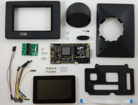
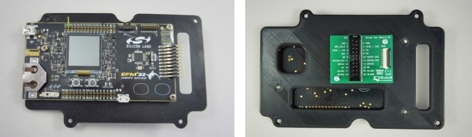
That is, the plans have never been to release something similar in series, or even to do the second such device. Therefore, and also because the device should be easily disassembled into parts, we enclose not a specially made compact printed circuit board, but just a few debugs from the manufacturer - with unused hardware blocks, connections from the design wires and the rest of disgrace.
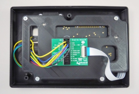
After consulting with colleagues involved in the supply and refinement of cases for electronic equipment, it was decided to take the back and leg from the standard OKW case, and print the front wall on their own. In addition to it, the “internal” parts were printed on the 3D printer — a small camera for installing the HY-271 sensor and parts for fixing the boards inside the case.
When creating a model for printing using SolidWorks and Polygon. The printer uses today's most popular technology - Fusing Deposition Modeling (FDM).
Printing is not at all my profile, so I’ll only say common words.
The essence of the technology of layer-by-layer welding is reflected in its name. After creating a three-dimensional model of the part and downloading this model to the printer, layer-by-layer application of hot plastic begins, which freezes immediately after the application of the next layer. Unlike other 3D printing technologies, an extruder is a moving element in FDM — a nozzle on which plastic melts and is squeezed onto a model.
The disadvantages of this printing technology are shrinking and low print resolution. Shrinking can affect (and affects) the size of the final product, and low print resolution causes a layered surface that is noticeable to the naked eye. However, these shortcomings are more than compensated by the low price of equipment and materials for layered printing, which is why in recent years we have heard about 3D printing from each iron.
Layered printing is great for creating piece products and prototypes for mass production. In my case, the print quality was enough for parts that fit inside the case, but the surface of the front cover of the case had to be refined - polished, polished, finished
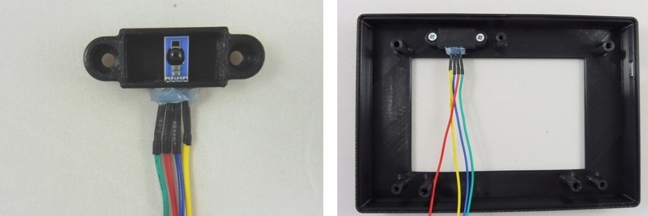
Let's proceed to the assembly. Let me remind you that the project uses the HYT-271 sensor - a model of a relative humidity sensor, made without a protective metal case. It was decided to place the sensor in a small chamber without a front wall, and attach this chamber to the front cover of the case, where rather large openings are provided for contact of the sensor with the environment.
A debug board with an EFM32 microcontroller on board and an adapter board for connecting the display are mounted on a printed plate. This plate also provides holes for attachment to the front cover of the case.
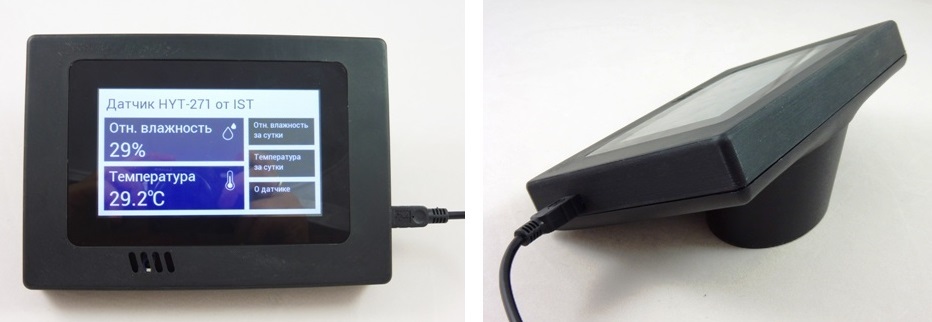
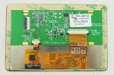
The TFT-display is mounted on the front cover. The display of the RVT43ULFNWC0x is designed for mounting into a hole - it is equipped with a decorative frame that has an adhesive strip on the back side and covers the edges of the hole.
2. How it all happened
Everything looks quite decent, but the accuracy of the assembled device turned out to be much lower than the accuracy of the same device in a disassembled state.
Error # 1
Of course, from the very beginning it was clear that the work of the temperature and relative humidity sensor, which is inside the case (albeit in a separate chamber), will be affected by the surrounding electronics. However, the introduced error should have been small, but we generally do not measure anything. The device simply demonstrates the work of the components, so that there is something to turn in your hands while you talk about the display or the sensor. In short, from the very beginning it was decided not to bother and not take out the sensor at a distance from other components.
But the error is not even that.
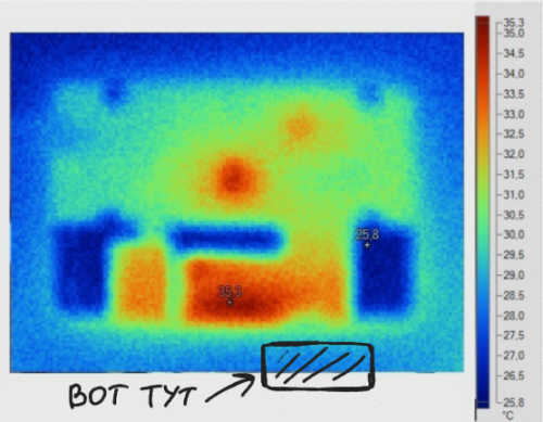
The camera containing the sensor is attached to the front wall of the case. There, on the front wall, about a centimeter higher, is a TFT touchscreen display. On the back of the display are the display management system - the graphics controller FT801 and the display matrix control circuit.
After several hours of operation, the TFT module heats up unevenly, with the most heat coming from the matrix control circuit. Already guessed where was the camera with the sensor?
Error # 2
When the device was reassembled, the error in temperature measurement, of course, decreased. However, the sensor still rolled - the measurement accuracy did not match the accuracy that the sensor showed before being installed in the case.
The riddle was solved simply. The relative humidity sensor has a sensitive element, the capacity of which varies in proportion to the relative humidity of the environment. The sensing element is built on the basis of a moisture-sensitive polymer, and this polymer is exposed to various gases. This is the trouble of all capacitive humidity sensors. The effect of some gases on the sensors of the HYT series is treated by heating (about 140 ° C for 2-3 minutes), the influence of other gases is irreversible.
In any case, my mistake was that the sensor was installed in the case immediately after printing. Stupidly happened - the body, in the end, still smelled of plastic! As a result, the polymer "breathed" in pairs of plastic and its output characteristic safely moved out.
Here is a story. Errors are taken into account and corrected, but this is not interesting either to read or write.
»Video showing the operation of the device can be viewed on youtube .
The source code for the microcontroller is available at developer.mbed.com .
"Links to articles describing the entire software development process are listed at the beginning of this article .
Conclusion
In conclusion, I traditionally thank the reader for his attention and remind you that questions about the use of products, about which we write on Habré, can also be asked by email, specified in my profile.
PS Yes, we are also engaged in cases for REA.
Source: https://habr.com/ru/post/312484/
All Articles