Basics of computer networks. Subject number 4. Network devices and types of cables used
Greetings to all! We got to the 4th topic. Let's talk today about the various network devices and cables used. We learn what distinguishes a switch from a router, what a hub is and much more. I invite those interested in cat.
Content
1) Basic network terms, OSI network model and TCP / IP protocol stack.
2) Top-level protocols.
3) Protocols of lower levels (transport, network and channel).
4) Network devices and types of cables used.
5) The concept of IP addressing, subnet masks and their calculation.
6) The concept of VLAN, Trunk and VTP and DTP protocols.
7) Spanning Tree Protocol: STP.
8) Channel Aggregation Protocol: Etherchannel.
9) Routing: static and dynamic on the example of RIP, OSPF and EIGRP.
10) Network Address Translation: NAT and PAT.
11) Reservation protocols for the first transition: FHRP.
12) Computer network security and virtual private networks: VPN.
13) Global networks and protocols used: PPP, HDLC, Frame Relay.
14) Introduction to IPv6 configuration and routing.
15) Network management and network monitoring.
PS Perhaps over time, the list will be added.
In earlier articles I wrote about various network models, protocols, services. But he spoke little about devices that work closely with this, and most importantly, how they all differ from each other. This knowledge is very important for the network engineer, so I will close this gap.
')
Fortunately, many devices are available in Cisco Packet Tracer (version 6.2), so after each described device, I will show this in practice.
So. The term network devices is applicable to those devices that are connected to a network segment and are able to receive and / or transmit some kind of data. The simplest and immediately comes to mind is a network card .
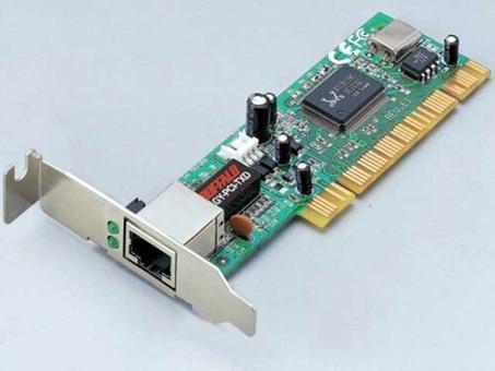
I think everyone saw her. It stands in almost every home computer. If not, then built into the motherboard.
Previously, it was possible to meet other types of it. For example, as in the picture below.

Pay attention to the input for the coaxial cable, which was previously used extensively. Now there are rarely where you will meet. If it is interesting to look at other species, then there are very good examples in CPT. For example, if you click on a computer, this window will open.
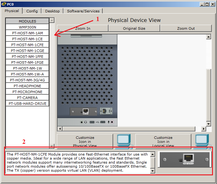
The module window is located on the left (indicated by 1 in the figure). For each module there is a short description and how it looks (indicated in the figure as 2). For example, I clicked on the PT-HOST-NM-1CFE module. This is a network card that uses Fast-Ethernet technology and is designed to work with twisted pair. Can work at speeds of 10 Mbps and 100 Mbps. Also supports VLAN technology, which will be the next article.
The work of such a card is simple. She has a MAC address (which I mentioned earlier), which she was assigned at the factory, and she can use it to communicate with other devices on the network. And it is not necessary to connect it to a switch or other device. You can connect it to another network card and organize communication between them. Thus, they used to connect 2 computers in one room. This is the simplest connection. Let's try to organize it in CPT.
I will depart a little from labs as there is an important remark here. There are 2 types of twisted pair. Straight (Straight-Through) and Cross (Cross-over). Direct is used when you need to connect 2 different devices. For example, a computer and a switch. A cross - when you need to connect 2 computers, 2 switches, etc. The structural difference is that pairs of wires are crimped differently. Below is a crimping scheme.
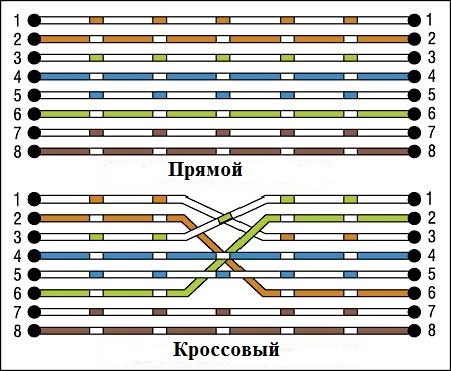
Accordingly, if you connect devices with the wrong cable, then nothing will work. If you are just starting your way, you may not encounter such a problem, since most modern devices support Auto-MDI (X) technology. This technology allows you to understand the device with whom it is connected and in what mode it works. Moreover, it is enough for at least one participant to support it for correct work. But in any case, it is necessary to know. Therefore, take note.
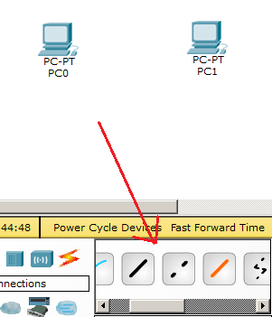
We return to the lab. I propose to connect 2 computers with a direct cable to make sure that this design will not work.
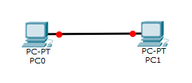
And as you can see, the ends of the cables are red, which indicates that the connection does not work.
We correct the error and connect the computers with a crossover cable.
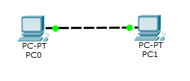
Observe the green lights. We rejoice and proceed to the configuration of IP-addresses. First we assign the address: 192.168.1.1 with a mask: 255.255.255.0. All the rest does not matter. And, accordingly, we will assign the IP address to the second computer: 192.168.1.2 with the same mask: 255.255.255.0. Check the connection between them.
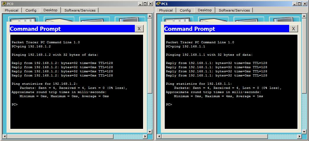
Ping successful! Who reluctant to connect 2 computers, a link to download.
The next device in the queue is a repeater or repeater .
If we consider from the point of view of the OSI model, then this device works on the first level. That is, on the physical. The device is very simple. The main task is to amplify the signal. If we recall a little course of school physics, then each cable has a signal attenuation limit. If we are talking about a twisted pair, then its maximum length can be up to 100 meters. (Vilos) And in order to enhance the signal, use this device. Ethernet repeater can amplify the signal by another 100 meters.
Due to the fact that currently PoE (Power over Ethernet) technology has gained popularity, repeaters are used as extension cables for remote devices (for example, IP cameras). In the pictures below you can get to know them.
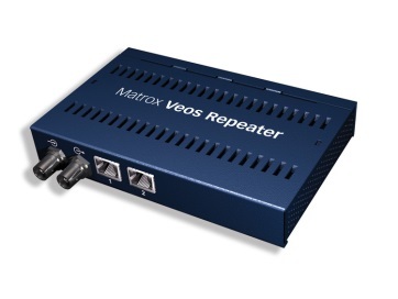
Repeater of the old sample (currently no longer produced)
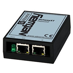
One of the modern repeaters.
It is present in CPT, so take a look at it.
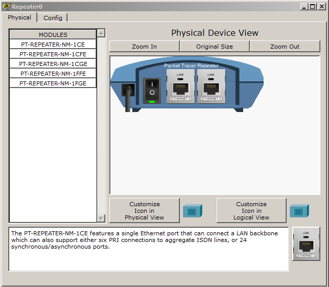
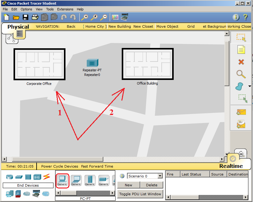
You can bring it closer, postpone it, change its interfaces. All at your discretion. I simulate a situation where we have 2 computers located far from each other and interconnected with a repeater.
I want to note an important function in CPT. In addition to building a logical topology, there is also a physical topology. A very handy thing when you need to check how something will work at a certain distance. I can not say that it works with an accuracy of one meter, but you can check the approximate results. You can switch between them in the upper left corner.
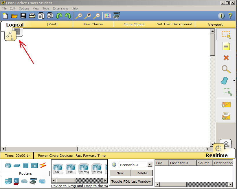
When switching to the physical, the following picture will open.
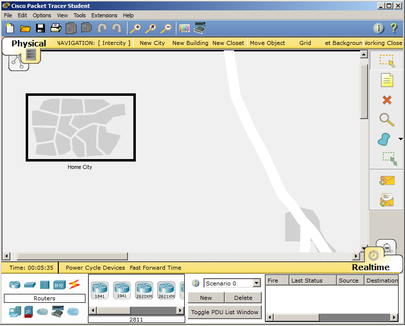
This is a conditional geographical map with the created city. You can build the same cities yourself and deploy long-distance communication. But, since the repeater only increases by 100 meters, you need to look for something closer to this distance. We click on Home City and get into the city.
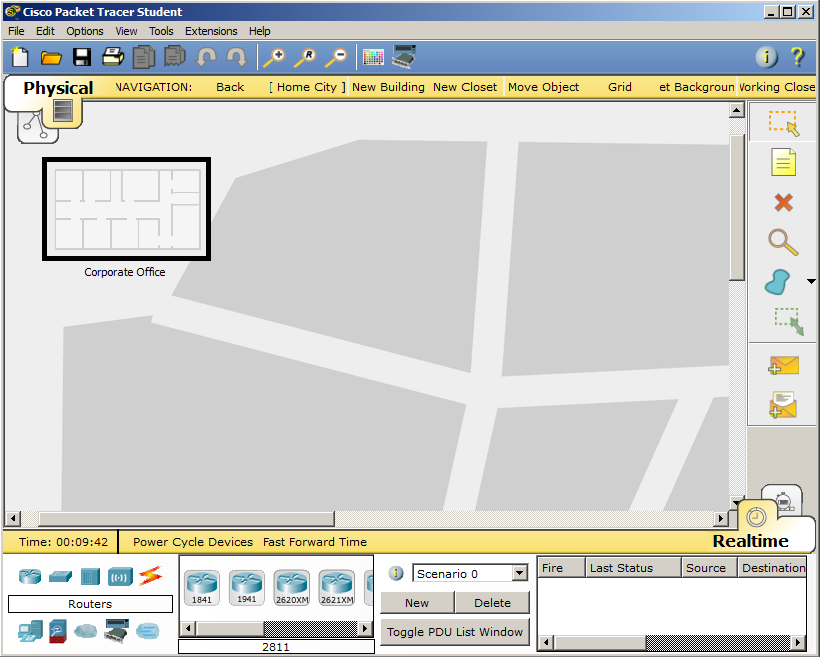
There is already some kind of corporate office. We will create another office and arrange communication between them using a repeater. This distance will already be more like the truth.
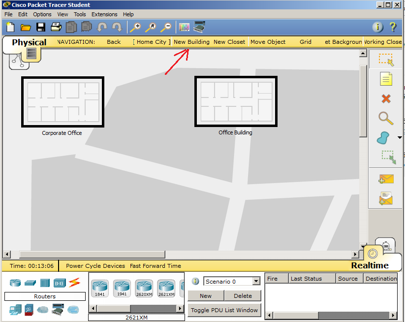
Click on the New Building and create another building. I will arrange it more comfortably.
Now is the time to arrange the nodes. First of all I will install a repeater between them. I go to the tab Hubs. I choose Repeater and put it as in the picture below.
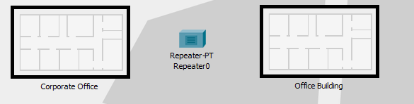
Now you need to arrange the computers. Of course, it’s crazy that in each office there is one computer, which are connected through a repeater. But for simplicity, let it be so. I go to the End Devices tab and select PC. And I will throw in each office on a computer, as in the picture below.
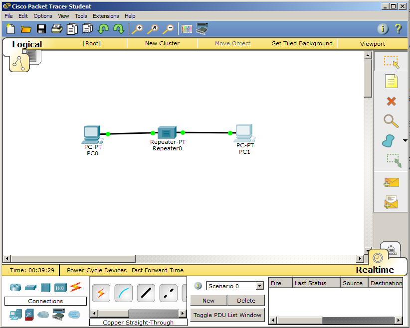
It's time to connect everything. I switch to the logical topology and observe the following picture:

Here I see all the devices that are present in the project. Although only the repeater is visible in the physical topology, the computers are hidden in the building. Connect them. Only we will connect with a direct cable, since these are different devices. Addressing will be the same as in the previous lab. The left one will have an IP address: 192.168.1.1 and a mask: 255.255.255.0, and the right one with an IP address: 192.168.1.2 and a similar mask: 255.255.255.0.
After we switch to the physical topology and observe the following.
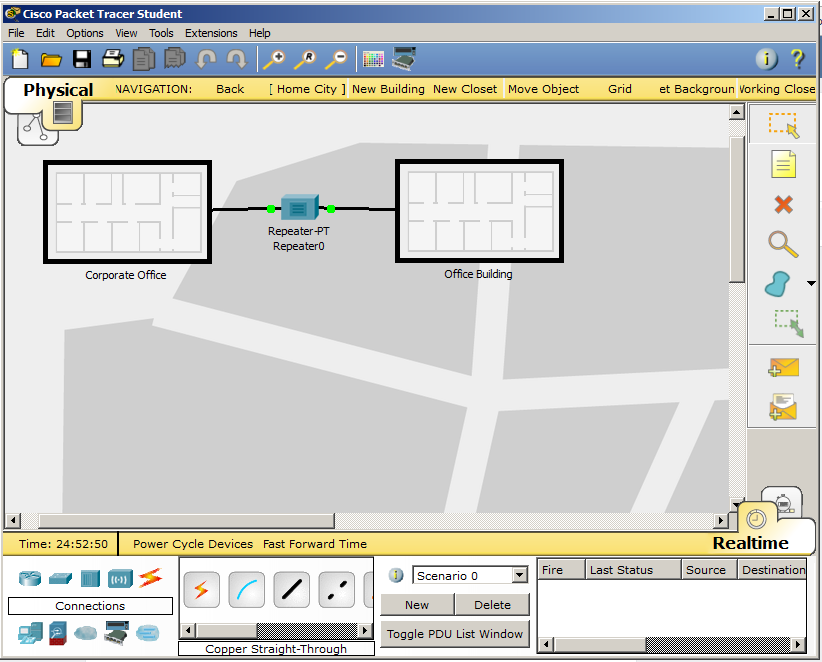
All connections that were made in the logical topology are automatically displayed in the physical. 2 offices connected. It's time to check availability with the ping command.
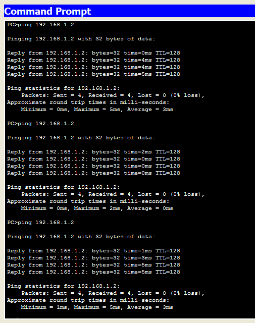
As you can see, everything works great. But pay attention to one thing. I deliberately pinged several times to show that each time we get different results (then 4ms, then 5ms). If before this time it was almost stable 0 ms, that is, without delays, then it is already present with a repeater.
This is how a repeater works. I give a link to download.
Next in line is a hub or hub . A device that covered popularity from the 90s until the early 2000s. Moreover, the word “hub” is so heavily populated with everything that so far many people call any network device with this name. Many still call it a repeater. Of course, this is not entirely true, since the repeater is the device shown above. But to say that this is a lie, too, is impossible. Since this is a multiport repeater. But it is more correct to call it a hub or a hub, in order to clearly distinguish this device from the repeater shown above.
Further to your attention I will present a couple of well-known hubs.

The hub from the company Netgear.
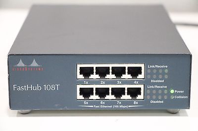
A hub from Cisco.
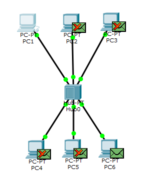
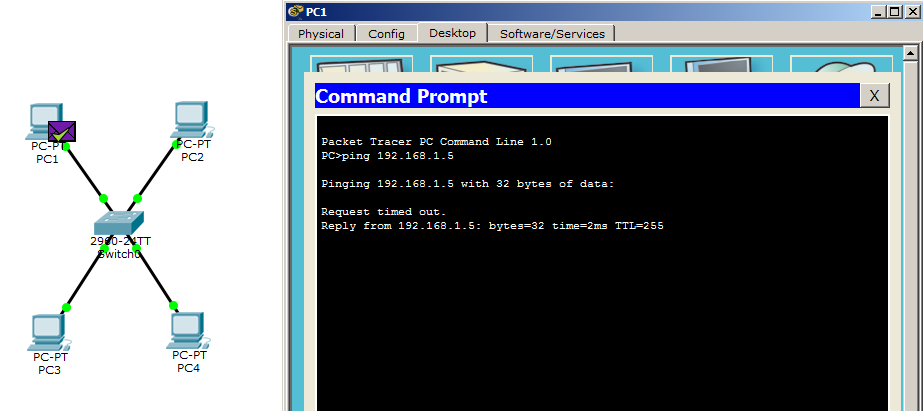
The logic of his work is simple. The signal received from the port is transmitted to all other ports except the original one. I turn to CPT and create a lab as in the image below.
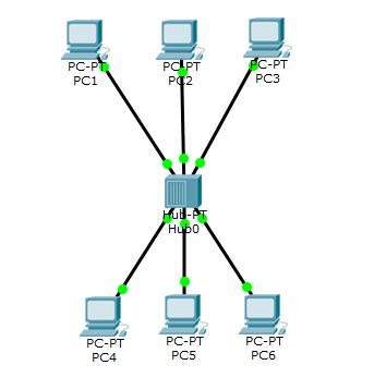
6 computers are connected to one hub. Hub is not necessary to configure. It works as soon as you pull it out of the box. But I configured the computers and bring the settings:
1) PC1: IP-192.168.1.1, Mask-255.255.255.0.
2) PC2: IP-192.168.1.2, Mask-255.255.255.0.
3) PC3: IP-192.168.1.3, Mask-255.255.255.0.
4) PC4: IP-192.168.1.4, Mask-255.255.255.0.
5) PC5: IP-192.168.1.5, Mask-255.255.255.0.
6) PC6: IP-192.168.1.6, Mask-255.255.255.0.
I’ll translate CPT into simulation mode and check availability to PC6 using PC1.
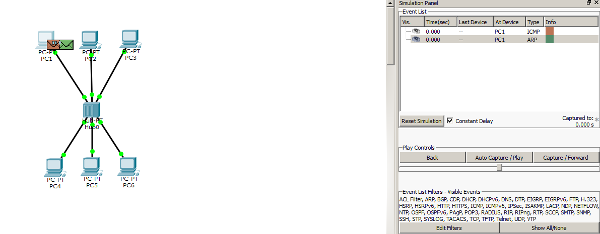
Formed 2 messages. One of them is ICMP, and the second is ARP. ICMP will not work as long as it does not know the PC6 MAC address. But ARP will immediately work to get the MAC address (this is explained in detail in the previous article). So PC1 sends ARP to the hub.
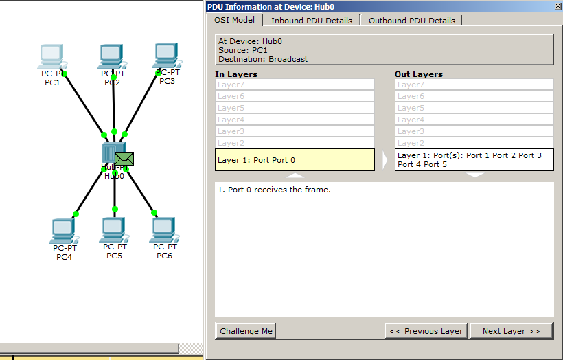
The message came, and I suggest to look closely at its contents. Although the message carries some information, for a hub it is just a stream of bits. He knows that the message came from port 0 and must be transferred to 1, 2, 3, 4, 5 ports.
And really. The message is sent to all computers, except outgoing. Accordingly, PC6 understands that this message is for him and will form the answer, and will ignore the rest of the computers. You can argue that the ARP protocol when searching for a MAC address always works this way, and you will be right. But let's see what happens next.
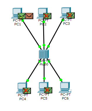
And what do we see ?! The message is also sent to all computers, except outgoing. Although the reverse ARP message contains the exact recipient.
Now that PC1 knows the PC6's MAC address, it will generate an ICMP message, which the hub will process in the same way as ARP. I restarted CPT, and now I have ICMP yellow.
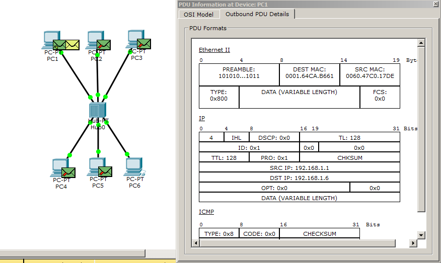
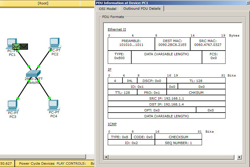
Before further viewing open the message and see what's inside. It is clearly visible that he has Source MAC, Destination MAC, Source IP and Destination IP. Accordingly, the message has a specific recipient.
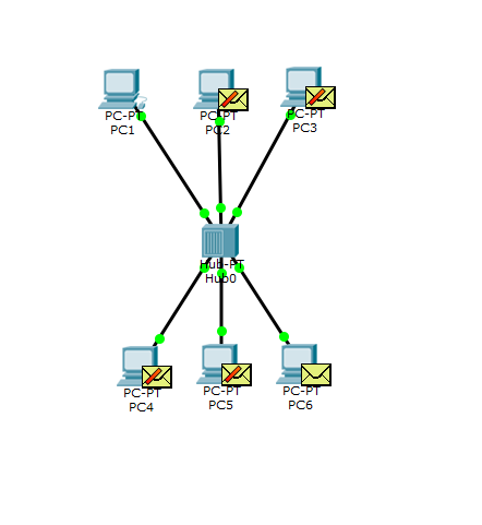
But despite the above, it will also be sent to all ports, except for outgoing. This is the essence of the hub. For those who want to personally see his work, here is a link to download.
If earlier this behavior did not cause strong concerns (when the number of computers was up to 10), then over time the number of computers and devices that connected to the network increased. This led to the fact that the network was very heavily loaded, and it became hard to work. And the entire network at that time worked in half duplex mode (half-duplex). This means that the same wire was transmitted or received. Accordingly, the more computers start broadcasting on the network, the greater the likelihood of a collision. It was necessary to urgently find a solution in order to somehow limit the network segments. And for her permission began to use bridges or bridge .
Bridge from Netgear

Now I will tell you what they are. It was already a smarter device that worked on the 2nd level of the OSI model. That is, it knew what MAC addresses are and how to work with them. Now each of its ports was assigned to a specific network segment, that is, it solved one of the most important problems. In addition, he had a filtration system. That is, he did not forward broadcast frames that were not intended for another network segment. He had his own table, where he wrote down who was sitting at which port. That is, the frame that came to the bridge was not blindly sent to another port, but was checked against the table, and if the addressee is sitting at the other port, the frame was released. Otherwise, the bridge destroyed it.
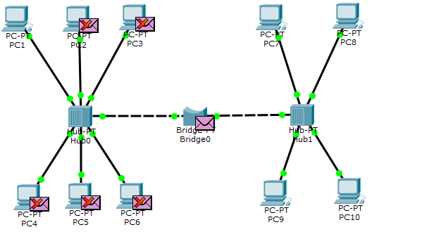
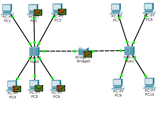
Read the theory and time of transition to practice. Since we need hubs and more than one computer in this lab, I took the previous lab as a basis and upgraded it. The only thing that upset is that the bridge in the CPT is conditionally implemented. It performs all the necessary functions, but you cannot go in and look at its table (although it is present with it). But it is not important. The main goal is to show the operation of this device. So in this lab was added a bridge and a hub with 4 computers. If you do not have enough ports on the hub to connect to the bridge, you can add an additional interface to it. Just remember to switch the switch on it before. I did not touch the 6 left computers, so their addressing did not change, but for the 4 right computers I’ll give below:
1) PC7: IP-192.168.1.7, Mask-255.255.255.0.
2) PC8: IP-192.168.1.8, Mask-255.255.255.0.
3) PC9: IP-192.168.1.9, Mask-255.255.255.0.
4) PC10: IP-192.168.1.10, Mask-255.255.255.0.
I switch to simulation mode and try to ping PC10 from PC1.
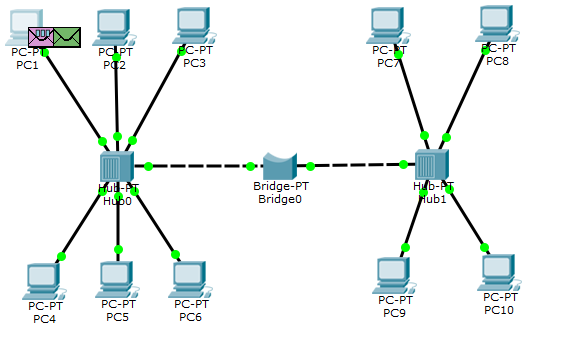
According to the standard scheme, 2 messages are created, but ARP is the first to go into battle.
The hub sends it to everyone except the port of the sender. And all his cast, except for the bridge. Although he is not addressed to the bridge, he also does not know if there is such a recipient there. Therefore, he sends it to check.
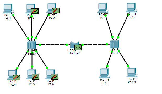
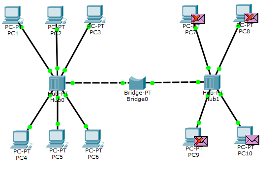
The hub on the right side works as expected, and in this segment is the recipient. He sends a reply message.

The hub works, and all nodes except the bridge drop it.
The bridge throws this message on the left hub. And he, in turn, throws it out to all participants. PC1 recognizes itself in this message and now sends ICMP.
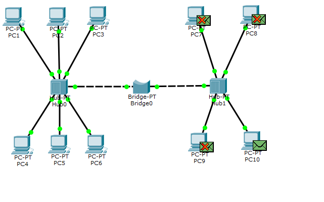
Hub fulfills. The message hits the bridge. He looks to see if he has such a recipient. He sees what is present and sends.
The hub sends it to everyone and PC10 receives it. A reciprocal ping will follow the same route.
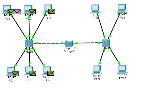
Let's look at the situation when the exchanging nodes are in the same segment, and you do not need to send a message across the bridge. Check the availability of PC5 with PC1.
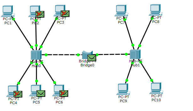
It sends to the ARP hub, and that, in turn, for all. And notice that 2 devices (bridge and PC5) became thoughtful. PC5 understands what it is for him, and sends the answer. And the bridge decides to check whether there is such a recipient on the right. He does not wait for the answer and understands that there is no such thing there.
Now that PC1 knows about PC5, it forms an ICMP for it.
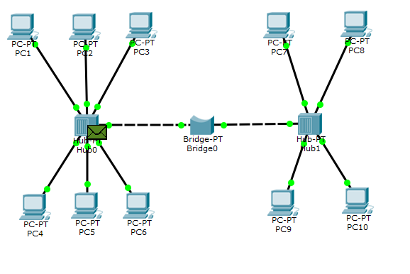
PC5, upon receiving it, prepares the answer. But the bridge now knows that there is no such recipient on the right and immediately discards such a frame. This shows how it filters.
This is how bridges worked and work (if they are used elsewhere). As you can see, the bridge created 2 segments or 2 collision domains. That is, everything that happens behind the left port of the bridge does not affect the right port in any way, unless the message is intended for a node in another segment. Thus, this has reduced the load on the network. I give a link to download.
Go ahead and talk about switches . Everyone probably heard about them, and many of you have worked with them. Switches are different, and they differ in their functions and, of course, price. Let's talk about them and highlight the main concepts. With the advent of bridges and their filtering, engineers wondered how to make a device that would separate not only network segments, but also computers. That is, to provide microsegmentation. When a device knows which port is sitting at which port, it will not transmit a message to all nodes destined for a specific node. The result is a switch. Like the bridge, it has its own table. It lists which port has a specific MAC address. Such a table is called a switching table. Writing to it occurs when the device begins to be active. For example, when sending a message, it leaves its MAC address in the header. The switch reads this header and understands what the sending device’s MAC address is and writes it down. Now, if a message comes for this particular device, he will send it to him. Other devices, he will not send a message.
However, do not forget that if you just got the switch out of the box and connect devices to it, it will not immediately know who is sitting at which port. Initially, the table is empty. And, as I wrote above, it will fill it as the node is active. This process is called a learning mode . But as soon as he fills it, everything will be fine. When a frame arrives at the switch, he will look at the header and read the destination MAC address. Next, he will look at his table and look for the port, behind which sits a node with this MAC address and, accordingly, sends it.
Switching processes at the switch and the bridge are similar. But there is an important difference: bridging at the bridges is software, and at the switches it is hardware. If the bridges were switched by the processor, then for the switches they came up with special ASIC microcircuits. These are specialized chips that are designed to perform a specific task. Consequently, this type of switching turned out to be much faster, which made switches so popular.
Every year, switches are becoming faster and smarter. If we talked about switches as devices of the 2nd level on the OSI model, then almost all modern switches from the Cisco company are able to work at levels higher. Such switches began to be called L2 + switches. Why L2 +, and not L3, I will now explain in practice.
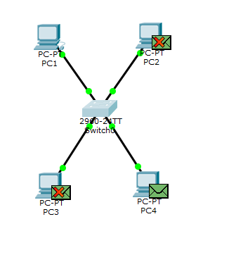
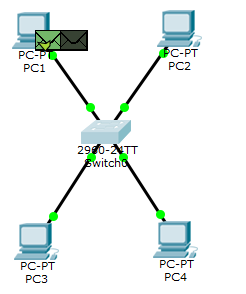
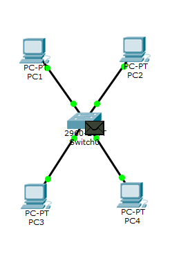
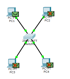
I open the CPT and assemble the lab as in the picture below.
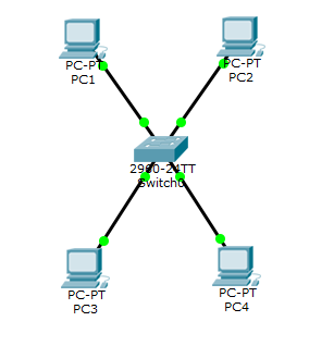
There is a switch and 4 computers. I have not yet changed the tradition of assigning IP addresses, but still give you a list:
1) PC1: IP-192.168.1.1, Mask-255.255.255.0.
2) PC2: IP-192.168.1.2, Mask-255.255.255.0.
3) PC3: IP-192.168.1.3, Mask-255.255.255.0.
4) PC4: IP-192.168.1.4, Mask-255.255.255.0.
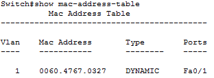
Since we just turned on the switch, it should have an empty MAC address table. Check it out. For verification, use the command “show mac-address-table”:
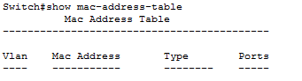
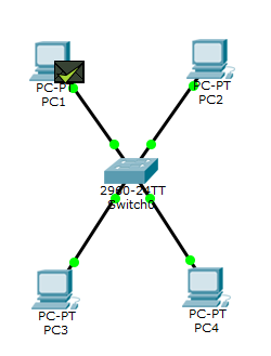
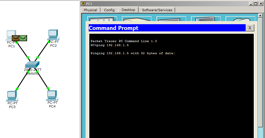
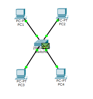
We make sure that it is empty, and move on. The simplest and fastest method of verification will be the ping command. Let us check the availability of PC4 using PC1. Naturally, the ARP protocol will have to work out first.
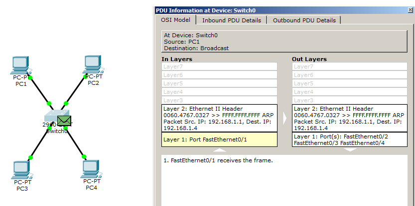
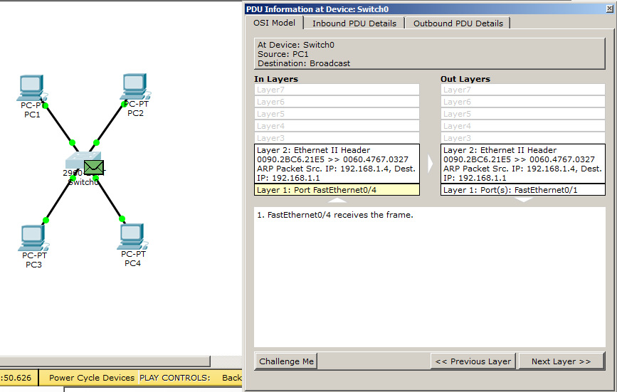
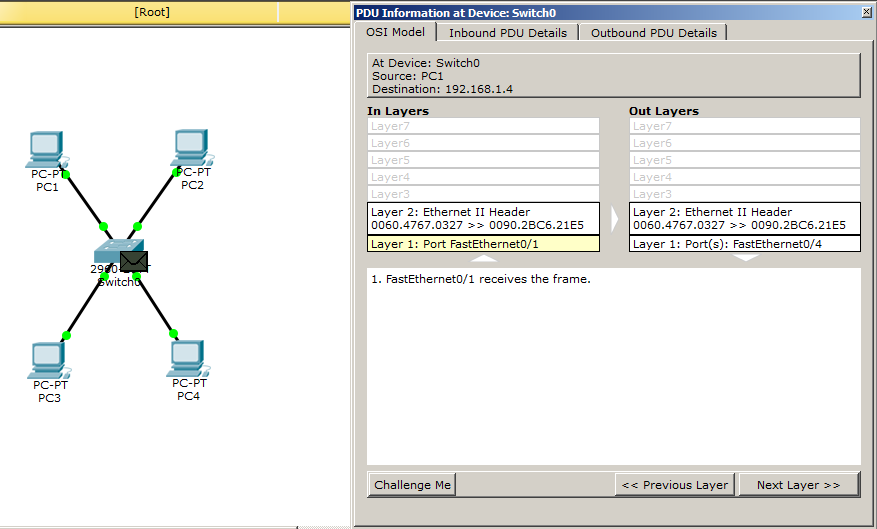
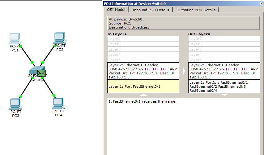
The switch is smart and can read what is packed on the second level. He sees the sender's MAC address, which he writes to his table. He also sees the broadcast MAC address (i.e. for all). So you need to send this frame to everyone except the sender. Pay attention to the 1st level. That is, at the entrance (In Layers), he received a frame from port 1, and on the output (Out Layers) he would send ports 2, 3 and 4. In general, it now works as a hub. I will not send a frame from the switch yet. Before this, you need to check the table of MAC-addresses.
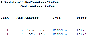
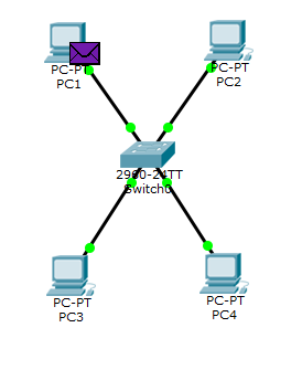
And I see the first entry. He recorded the MAC address and port from which it was obtained. Perfectly! We are looking at what will happen next.
It sends ARP to everyone except the sender. And we see that PC4 understood what it is for it, and forms the answer. All the rest of this frame discarded.
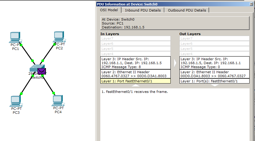
The switch receives the answer and reads it. At the second level, it sees the sender's MAC address and the recipient's MAC address. He sees the sender's MAC address for the first time, so he immediately enters it into his table. But he already knows the recipient's MAC address, so he will send it only to the 1st port. Pay attention to the data of the 1st level. He received it from the 4th port, and sent it to the 1st. But before sending check the table.
And really. The MAC address was entered. I click on Capture / Forward.
We see that the message was sent only to the 1st port (that is, for PC1). So the hub didn't exactly do that. Next, an ICMP message is being generated.
It works on level 3. We send.
It reaches the switch. We open and see that despite the fact that the message has a heading of the 3rd level, the switch is on the drum. He reads only the 2nd level heading and makes a decision. The MAC address of PC4 he knows and knows which port to send.
We look, how it will fulfill.
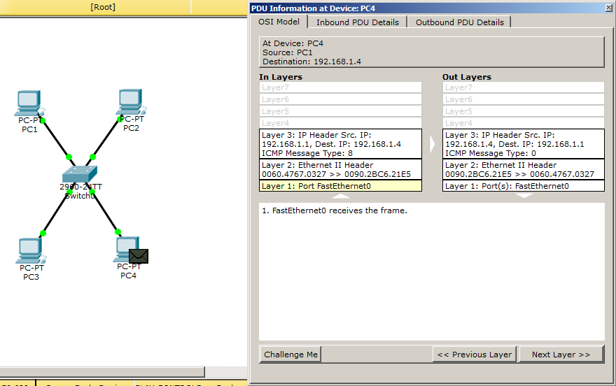
And it works out correctly. The message is sent only to the 4th port. PC4 forms the answer.
And the ICMP message without problems comes to PC1. Here is the whole principle of the switch. Now I will explain why this switch is called the L2 + switch. Lab work remains the same, except for a couple of changes on the switch itself. Above, we talked about the fact that switches work at the 2nd level of the OSI model. But over time, engineers have come up with managed switches. That is, it is no longer just a piece of hardware, which works by itself, and it is not possible to change something during its operation, but a smarter device that has the ability to set some parameters (for example, IP address) and configure it for remote control. I will demonstrate with an example. I open the previous lab and I am interested in the switch here. I go to it and assign a free IP address.
Switch> enable - switch to privileged mode. From here, most teams are available.
Switch # configure terminal - switch to global configuration mode. In this mode, you can enter commands that allow you to configure the general characteristics of the system. From the global configuration mode, you can switch to a variety of configuration modes specific to a particular protocol or function.
Switch (config) #interface vlan 1 - since this is a Layer 2 switch, you cannot assign an IP address to the port. But it can be assigned to a virtual interface. Therefore, I choose it and move on.
Switch (config-if) #ip address 192.168.1.5 255.255.255.0 - I assign him one of the free IP addresses: 192.168.1.5 and the mask: 255.255.255.0.
Switch (config-if) #no shutdown - turn on the interface. By default it is off.
The switch is configured and I suggest to check its availability with the ping command. I will do this with PC1.
I think that it will not be a secret for anyone any longer, that initially 2 messages are created. So the first is ARP.
And here comes the CPT glitch. He gets an ARP. Reveals it, sees that the IP address is the destination of it. But still wants to send it to everyone. Only PC1 he will send a reply ARP, and the rest will send ARP from PC1. We will observe further events.

ARPs reached the nodes. PC1 now knows the MAC address of the switch virtual interface. What the picture below shows.
It's time for ICMP messages. Generates it and launches it.
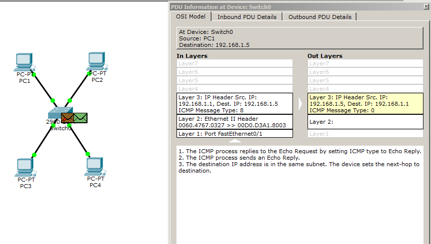
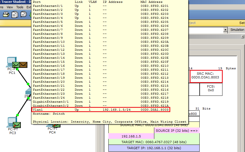
The ICMP message reaches the switch. We look, that inside. And we see that the switch really was able to read the level 3 heading. He recognizes himself, but another glitch happens. Look at the "Out Layers" column. He does not know what the MAC address of the PC1, which of course is nonsense. And I will show it now. When the ICMP message arrived (column “In Layers”), in the headers of levels 2 and 3, the sender's MAC address and the recipient's IP address were recorded. That is, he knew which MAC address he needed in order to send a reply. Without further promotion of the package, we will look at the switching table.
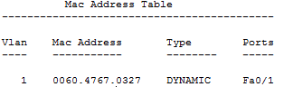
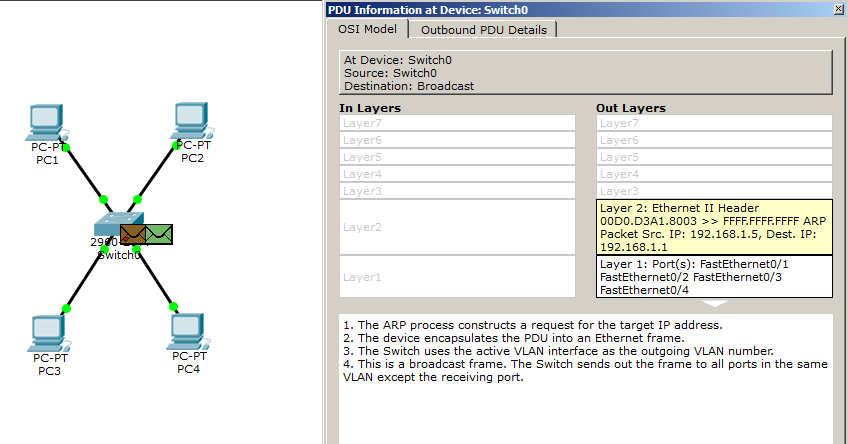
We see that this MAC address is really present. Well, since he "does not know" the PC1 MAC address, he is forced to launch the ARP protocol. Let's see what comes of it.
PC1 receives a message. He is shocked and perplexed because he already gave him his MAC address. But once asked, then send again.
The switch receives the response and updates its table. However, he forgets that you need to answer ping. Because before that he dropped it. What will happen next? That first ICMP request was lost and no one remembers about it anymore. The request timer for PC1 expires, as the picture below shows.

PC1 decides to send the second ICMP message.
The switch gets it and starts reading the headers. This time everything works well. He recognizes himself in him and knows who to answer.
The package successfully reaches the computer. You can verify this by paying attention to the screenshot from the console. Then it will generate 2 more such ICMP messages (4 in total). I will not show them, as they duplicate previous actions. Despite the fact that CPT had a small glitch, he forced himself to study in detail, which is sometimes very useful. Due to the fact that the switch was able to read the Level 3 header and respond to the ICMP message (he could also check the availability of any node himself), they began to call him the L2 + switch. Pure L2 switches with IP addresses are not able to work. But the question is, why is this switch not L3? And everything is covered in the fact that he does not know how to perform routing (transfer of packets from one channel medium to another). There are, of course, L3 switches, but we'll talk about them when we analyze the router. I attach a link to this lab.
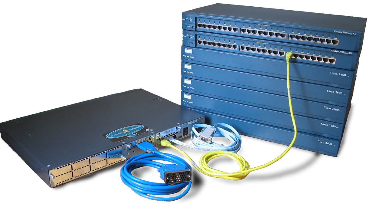
So, we meet a router or router . In principle, you have already seen how it works in previous articles. But refresh once again briefly.
A router is a device designed to forward packets from one channel medium to another. Also, its main function is to choose the best route for the package. Many people call this device a gateway. As if it is necessary to transfer some packet from one channel medium to another, the gateway will be the intermediate device.
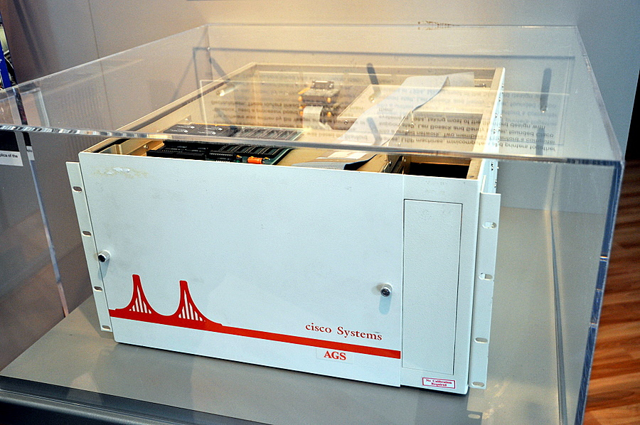
The device itself is very old. If you believe the stories, the first router was created in 1976 and united 3 local networks. Here, for example, is one of the first Cisco routers (even when the name began with a small letter).
Now there are too many of them. Moreover, they are divided by application. There are home, trunk and so on. Here, for example, is one of the modern trunk routers.
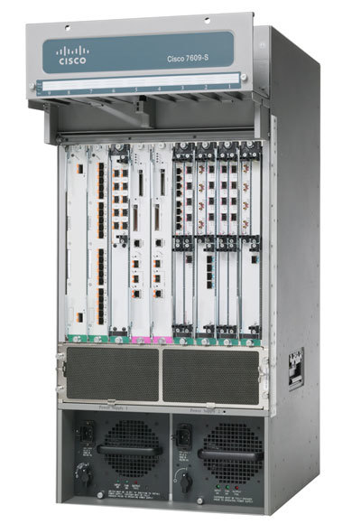
Cisco 7600 Series Routers
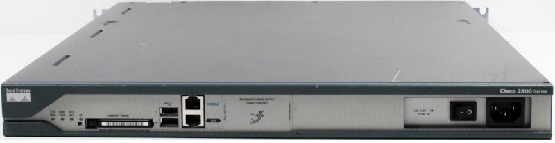
Or for example Cisco 2811, which will be used in the next lab.
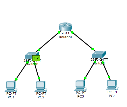
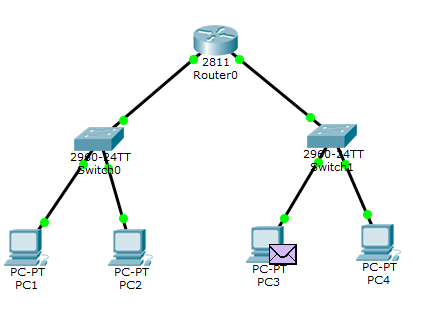
I propose to collect lab and go to practice.
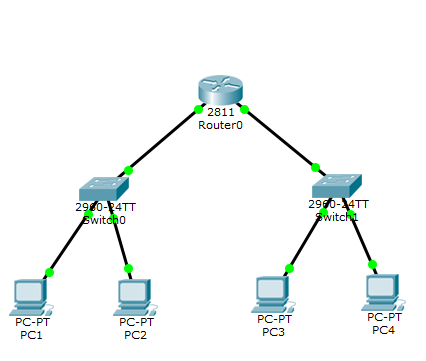
Added one router that will redirect packets from one channel environment to another. And 2 switches to which 2 computers are connected. Computer settings are as follows.
1) PC1: IP-192.168.1.2, Mask-255.255.255.0, Gateway: 192.168.1.1.
2) PC2: IP-192.168.1.3, Mask-255.255.255.0, Gateway: 192.168.1.1.
3) PC3: IP-192.168.2.2, Mask-255.255.255.0, Gateway: 192.168.2.1.
4) PC4: IP-192.168.2.3, Mask-255.255.255.0, Gateway: 192.168.2.1.
As you can see, the parameter of the main gateway has been added (Gateway). For computers in the left segment it is one, and for computers in the right segment another. Switches remain without changing settings. But the router requires configuration. Go to him.
Router> enable - switch to privileged mode.
Router # configure terminal - switch to global configuration mode.
Router (config) #interface fastEthernet 0/0 - switch to the interface configuration mode.
Router (config-if) #ip address 192.168.1.1 255.255.255.0 - assign it an IP address. This interface will be the gateway for the left network segment.
Router (config-if) #interface fastEthernet 0/1 — switches to the configuration mode of this interface.
Router (config-if) #ip address 192.168.2.1 255.255.255.0 - assign it an IP address. This interface will be the gateway for the right network segment.
Router # copy running-config startup-config - save the configuration
The router is configured, and you can view the routing table with the show ip route command.
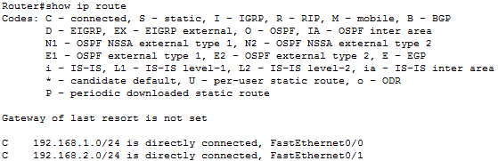
We see 2 connected networks. It is not necessary to register a specific routing setting, since we have segments connected through one router.
Time to check PC3 availability using PC1.
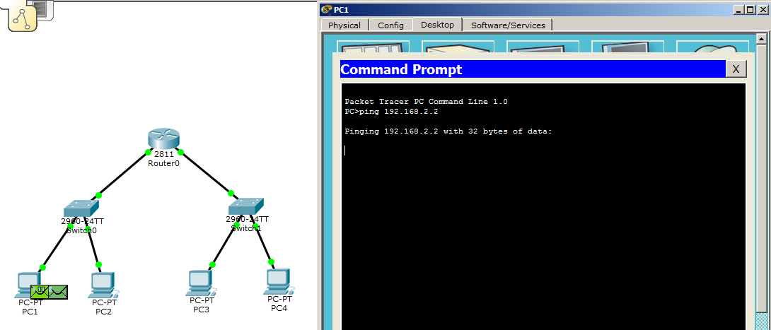
By simple mathematics, PC1 understands that the recipient is not on its network, and therefore it is necessary to transfer through the main gateway. But there is a problem that he does not know the MAC address of the gateway. In this regard, lets in the exploration of ARP.
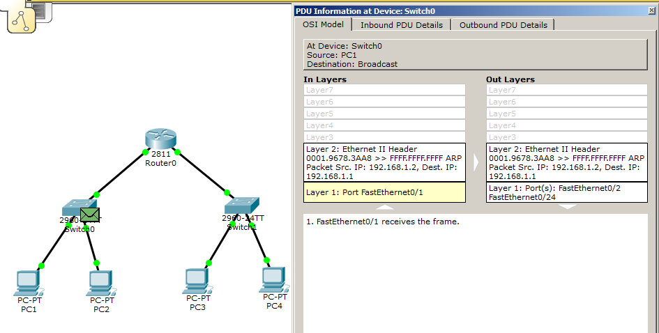
ARP gets on the switch, and look at the header. And we see that in Destination IP: 192.168.1.1.

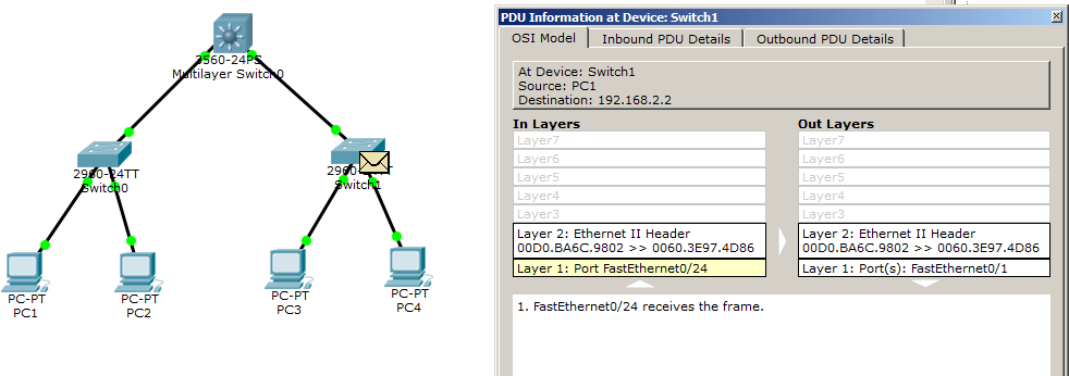
He sends it on, and the router understands what it is for him. And sends the answer.
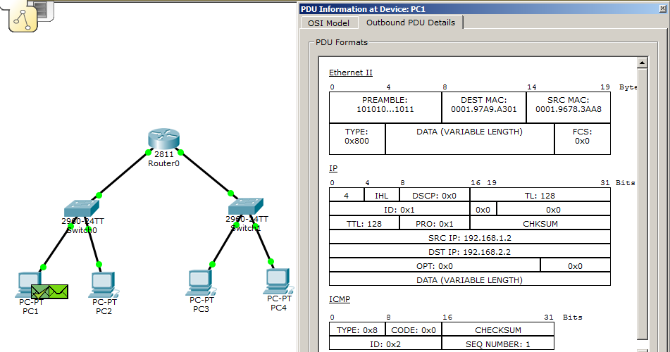
The ARP reply reaches the computer and it forms an ICMP message. Please note that the destination IP address is the PC3 address. And the destination MAC address is the address of the router.
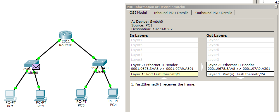
The switch reads the Ethernet header and sends it to the router.

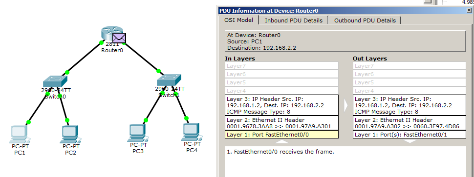
The router, having received this message, understands that it does not know who is on the network with IP: 192.168.2.2. Discards the ICMP message and starts the ARP.

The switch receiving the ARP, immediately sends it. There is a recipient who forms the answer.

I, with your permission, will not show the processes that are duplicated, because of their obviousness. So ARP will reach the router, and he now knows the PC3's MAC address.
In the meantime, the PC1 timer expires and it forms the following ICMP message.

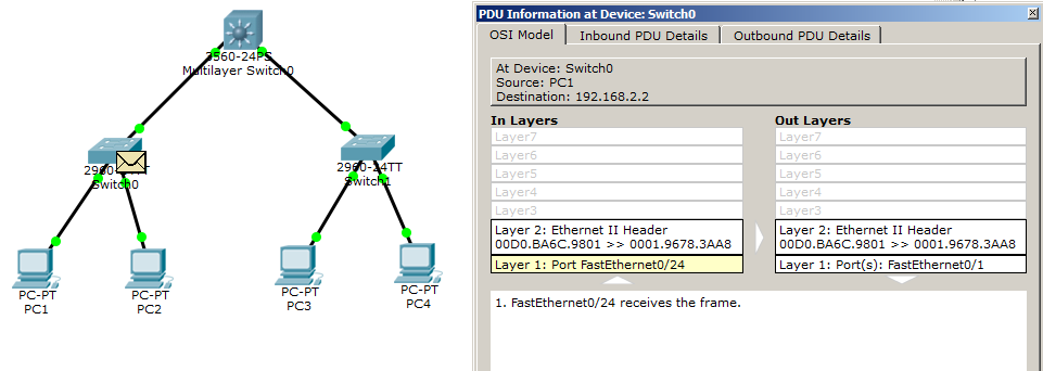
The switch header decides to send this message to the router.
The router, having looked through the header, understands that it is necessary to transfer it to another channel medium, and changes the fields in the Ethernet header.

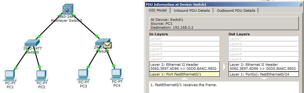
It comes to the switch, where he understands that the message must be sent to PC3, that is, to the 1st port.
PC3 forms the answer.
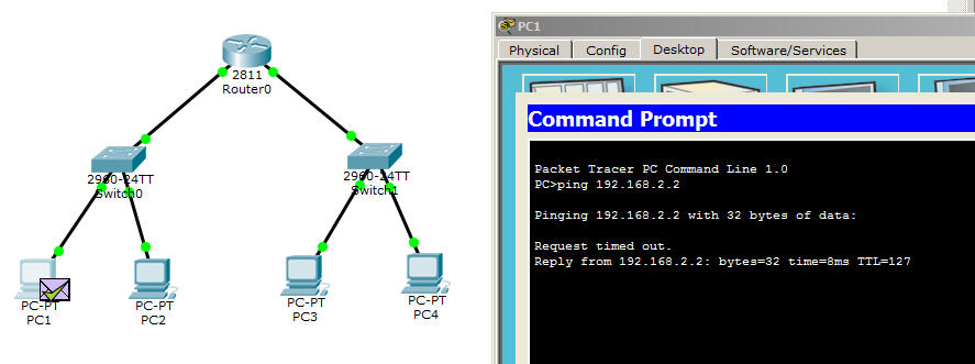
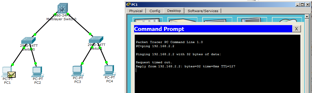
As a result, the answer comes to PC1, as indicated by the console window.
Here is the whole principle of the router. If you read the previous articles, then you learned a little about the basics of working with the router. Another of the router's chips is the choice of the best route, but this will be discussed in the next article. Well, according to tradition, I provide a download link.
We talked about the router, and I propose to disassemble the L3 switch . It is also called the MLS (Multi Layer Switch) switch. Its difference from the usual switch is that it performs routing. This type of switch has become so popular that many large vendors began to invest in its development. Now on the market you can find L3 switches from manufacturers such as HP, TP-Link, Cisco and so on. Below are a few models.
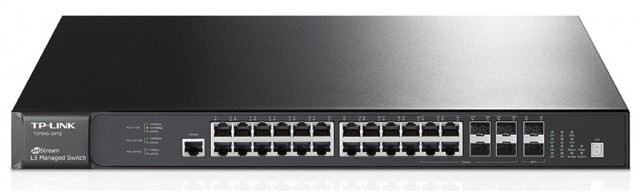
TP-Link L3 switch
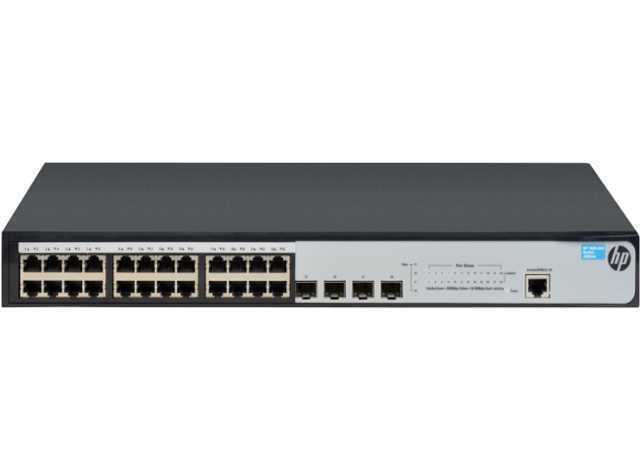
HP L3 Switch
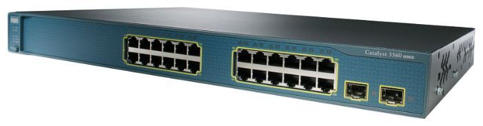
Cisco L3 switch
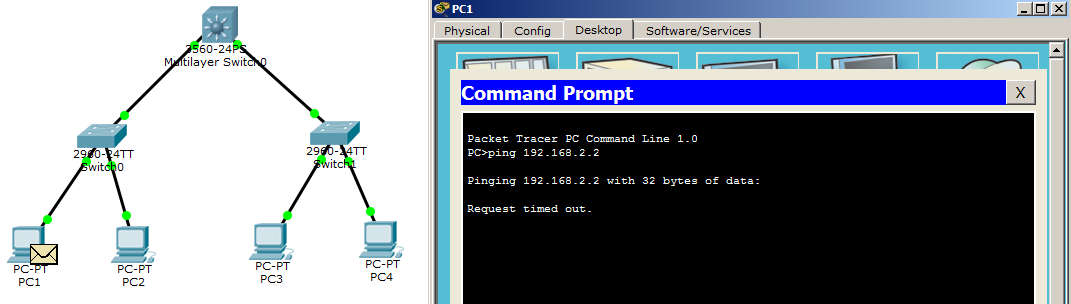
I propose to go to practice. I will take as a basis the previous laboratory work. But instead of the router I will put the L3 switch.

Computers are configured. It remains to configure the L3 switch. It is configured a little differently than the router. We proceed to configure it.
Switch> enable - switch to privileged mode.
Switch # configure terminal - switch to global configuration mode.
Switch (config) #interface fastEthernet 0/1 - go to interface configuration fa0 / 1.
Switch (config-if) #no switchport - transfer the port to the “router” mode. Without this command, you will not be able to hang an IP address on it.
Switch (config-if) #ip address 192.168.1.1 255.255.255.0 - assign an IP address.
Switch (config-if) #interface fastEthernet 0/2 — goes to configure the fa0 / 2 interface.
Switch (config-if) #no switchport
Switch (config-if) #ip address 192.168.2.1 255.255.255.0 - assign an IP address.
Switch (config) #ip routing - enable routing on the interface.
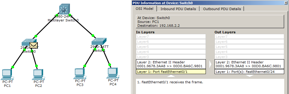
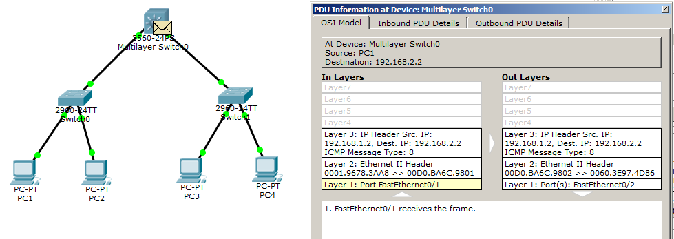
Setup is complete. It's time to go to the ping command. I did not show the work of the ARP team. I think each of you knows how it works, and began to record the moments when ICMP began to work. I give detailed pictures.


I think the process is clear. It is no different from what happened when the router was there. Now I’ll answer the question: The difference between the L3 switch and the router, and which is better. I, in my time, had been looking for an answer to this question for a very long time. And found it here . In short, the biggest difference in them is the price. Due to the fact that the L3 switch uses integrated circuits for special purposes, it is faster and therefore more expensive. I will not duplicate his article, so read. There, indeed, very well written about it! From myself just add a link to the ready lab.
I forgot to mention another device. And this is a dial-up modem . The very device with which many began to go online. The only thing he needed was a telephone network. The computer connected to the modem established a connection with the provider, which assigned him a channel and gave access. This process was called dialing. Due to the fact that since that time, technology has leaped far ahead, then such a connection is already in few places. Although they are still found in places with low population or in individual countries. Let's see what these devices looked like.
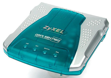
Zyxel modem

Modem from US Robotics
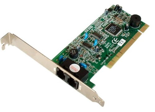
Later, network adapters with a built-in modem appeared. That is, the telephone line was connected directly to the computer. Below is one of these samples.
For a long time I fumbled with the question to assemble a simple lab and show how it used to work. It turned out something incomprehensible, but interesting.
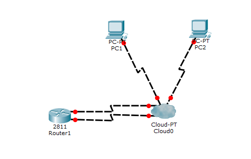
So what is what. We have 2 computers with modem interfaces. And connected to the cloud (this is a kind of global network emulation. A device with multiple interfaces) using a telephone cable. And to the left is a router connected by 2 telephone cables to the cloud. I will show how to change the interfaces on the computer.
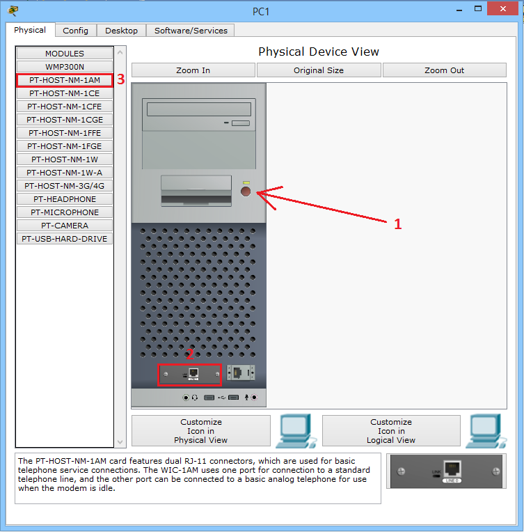
1) Turning off the power.
2) Pull out the connector with the mouse and pull into the column with the modules.
3) Select the modem module and insert it into an empty space.
And turn on the power back.
We perform the same operation with the router.
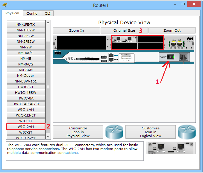
1) Turn off the power.
2) Select the module and insert it into one of the free slots.
3) Turn on the power back.
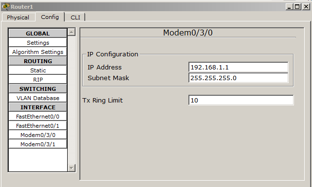
Now we are going to configure the router. The bottom line is that using the CLI to hang up addresses on new modules does not work, because it was not provided for in CPT. But you can do this through the "Config" tab.
Next, we will create 2 DHCP pools (that is, on each computer its own subnet) and exclude in advance the IP addresses that are already used on the router.
Router # configure terminal - switch to global configuration mode.
Router (config) #ip dhcp excluded-address 192.168.1.1 - exclude from the issue the address that hangs on the Modem 0/3/0 interface.
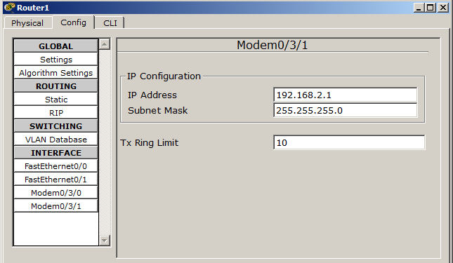
Router (config) #ip dhcp excluded-address 192.168.2.1 - exclude from the issue the address that hangs on the Modem 0/3/1 interface.
Router (config) #ip dhcp pool FOR-PC1 - create a pool for PC1
Router (dhcp-config) #network 192.168.1.0 255.255.255.0 - we announce the network.
Router (dhcp-config) # default-router 192.168.1.1 - we specify the main gateway.
Router (config) #ip dhcp pool FOR-PC2 - create a pool for PC2
Router (dhcp-config) #network 192.168.2.0 255.255.255.0 - we announce the network.
Router (dhcp-config) # default-router 192.168.2.1 - we specify the main gateway.
In order for computers to connect, they must be authenticated. To do this, create a login and password (it will be the same for two computers).
Router (config) #username admin password nimda - create a user with login: admin and password: nimda.
Save the configuration and proceed to setting up our cloud. First, let's see what interface where it looks.
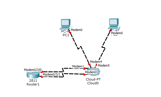
Now they need to assign numbers. For simplicity, I use the 3-digit numbers.
Modem4 = 111
Modem5 = 222
Modem1 = 333
Modem0 = 444
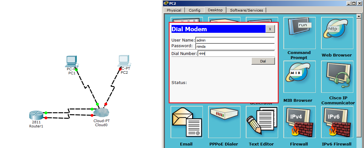
A little out of order, but this is not the main thing. At this stage, the basic setup is complete and it is time to test the work. I open PC1 and go to the Desktop tab.
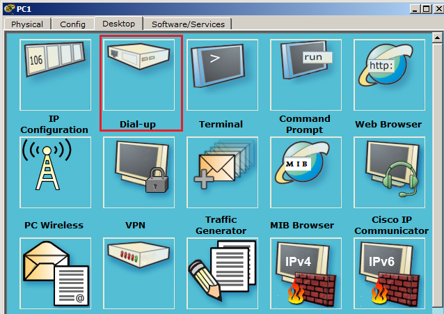
I think, as you guessed, you need a Dial-up tab. We open it.
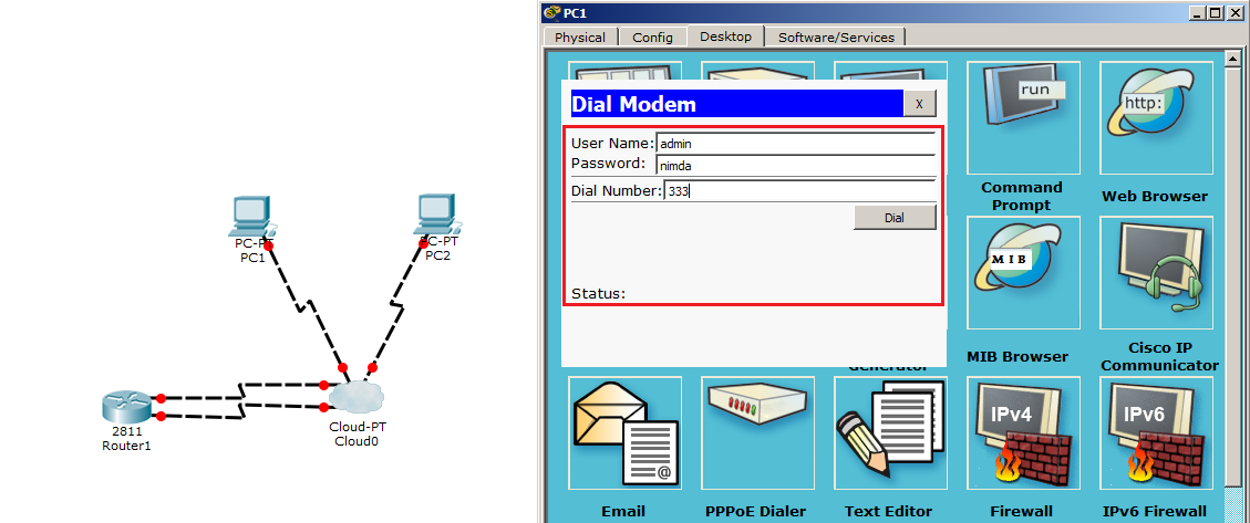
A window opens where you need to enter a username, password and number. Enter as in the picture. And press the Dial button.
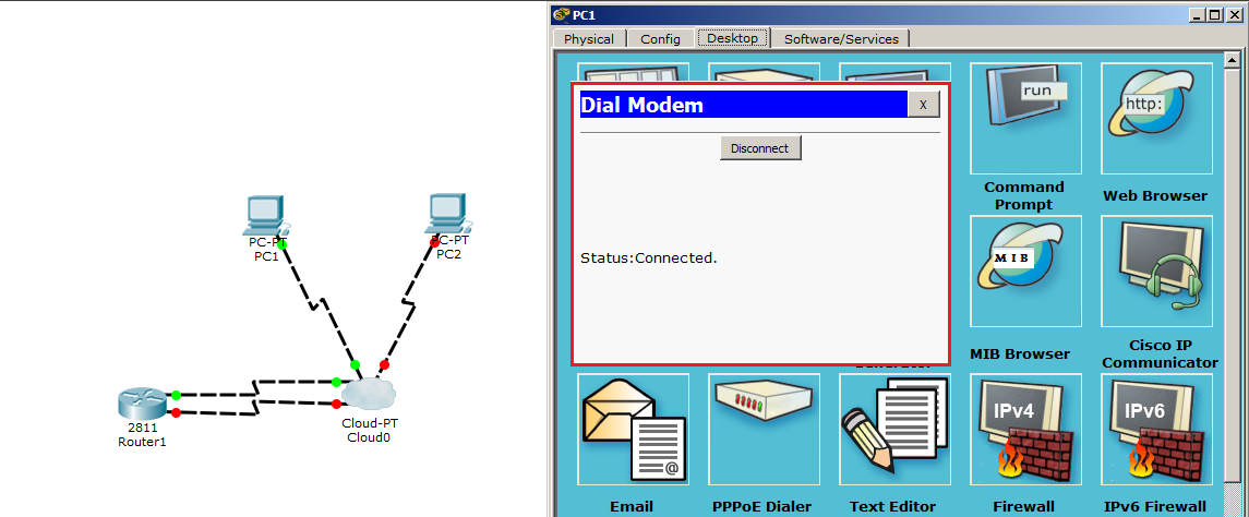
We see that the connection is established. What the Status indicates: Connected and green lights in the diagram. Once the connection is established, request an IP address from the DHCP server. Go to the Desktop tab and select IP Configuration.
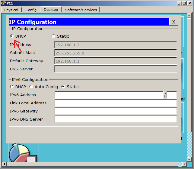
We select DHCP, and the computer receives the address from the desired subnet. Fine!
Now we will do the same procedures with the second computer.
Please note that the login and password is the same and the number is different.
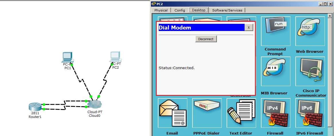
The connection has been established.

We get the address 192.168.2.2. The address is derived from the second pool, as intended.
Use the ping command and get to PC2 from PC1.

Ping passes, but with a delay. But this is an error.
The task was to show how dial-up works, with which we managed. Download and try!
This is probably the last device that we consider. Of course, this is not the limit, and a huge amount of them. There are all sorts of brandmauery (software and hardware), voice gateways for IP telephony, wireless devices. But this is already a specific equipment, and I don’t see the point in this cycle, as it will not be the basics, but an encyclopedia on network devices.
It remains to mention the cables used in our time.The most common cable is a twisted pair . It transmits signals using electrical signals. As the name implies, it uses twisted pair conductors, which are isolated between each other. Svivanie allows to reduce the influence of electromagnetic fields from external sources. At present, the most popular categories are 5e and above. Starting with this category, pairs of wires are twisted with different intensity, which allows to reduce the interference that they create and interfere with each other. Twisted pair is shielded and unshielded. If the cable marking starts with the letter U, it means that the cable is unshielded. The letter S means that the wire braid is used as the screen, and if F, then the foil is used as the screen.
For example, if you meet the label U / UTP (Unshielded Twisted Pair) - then this is a regular twisted pair without a screen. And, for example, F / UTP (Shielded Twisted Pair) means that the cable is shielded with foil, but the twisted wires themselves are not screened. That is, the first letter indicates the overall cable screen, and after the "/" sign, the wires themselves are shielded. F / FTP marking means that each pair is shielded with foil and in addition all pairs are placed in another foil shield.
I will give a good picture of the types of screening:

I will say a few words about the categories of cable. The higher it is, the higher the transmission rate and bandwidth. I will give a brief comparison of the category of cable to speed and bandwidth. There are a lot of these tables on the Internet, but whatever you are looking for, I will duplicate it.
Category 1 (bandwidth 100 Hz.) - up to 56 Kbps.
Category 2 (bandwidth 1 MHz.) - up to 4 Mbit / s.
Category 3 (bandwidth 16 MHz.) - up to 10 Mbit / s.
Category 4 (bandwidth 20 MHz.) - up to 16 Mbit / s.
Category 5 (bandwidth 100 MHz.) - up to 100 Mbit / s.
Category 5e (bandwidth 125 MHz.) - up to 100 Mbps when using 2 pairs and up to 1 Gbit / s when using 4 pairs.
Category 6 (bandwidth 250 MHz.) - up to 1 Gbit / s when using 4 pairs and
up to 10 Gbit / s with a cable length not exceeding 55 m.
Category 6e (bandwidth 500 MHz.) - up to 1 Gbit / s when using 4 pairs and
up to 10 Gbit / s with a cable length of no more than 100 m.
Category 7 (bandwidth 600 MHz) - up to 10 Gbit / s when using 4 pairs.
Category 7a (bandwidth 700-1200 MHz) - up to 10 Gbit / s using 4 pairs, up to 40 Gbit / s with a cable length of no more than 50 m and up to 100 Gbit / s with a cable length of no more than 15 m.
Despite their number, 5e and 6 appear in everyday use. This is quite enough to connect users to modern infrastructure. And in connection with the latest news, the new 802.3bz standard was approved. It will increase the maximum speed limit to 2.5 and 5 Gb / s using the same cables 5e and 6. So they still have a future.
At the end of a twisted pair cable is an 8P8C connector (which means 8 positions for 8 contacts), which many people call RJ-45.
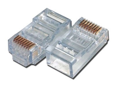
It connects to the cable with a special tool called a crimper.

I believe that this tool should be at every admin.
Next are the fiber optic cables (English optic fiber cable) . Now they are the basis of the modern Internet, as they can transmit data over long distances and are almost not subject to fading. If we talk about their design, then they all have a similar structure.

1) The core is located in the center (it is also called the core). It is the main light transmitting part. It is made of quartz glass.
2) Next comes the shell (alternative name damper). Its main task is to prevent the radiation from leaving the core. That is, it is a kind of border. It also, like the core, consists of quartz glass, however, the refractive index of the shell is lower. This is necessary so that he can completely reflect the light.
3) And the last part is the protective shell.
These are the main components of fiber optic cable. As it was written before, it consists practically of glass, which means it is very fragile. If, for example, twisted pair can work, even if the external insulation is damaged, the cable is bent in 10 places and the chair constantly travels over it, then for optical fiber this is very critical. Bending can only be done at a certain angle, which depends on the length of the cable. This is his fault. But there are huge benefits. If the length of the twisted pair without reinforcing sections can not exceed 100 meters. For example, for multimode fiber-optic cable, it is 500 m, and for single-mode fiber it is about 10 km.
Since we have reached single-mode and multi-mode cables, let's break them down in more detail. I will not go much into the physics of cables, but I will show you the basics. And at the end of the comparison I will show where to use which one.
Let's start with a multimode cable.

With the help of this cable you can transmit several light signals that will differ between themselves in wavelengths and phases. To correctly transmit several signals, you need to take a larger core. And this suggests that the larger the diameter of the core, the more dissipation it will cause. That in turn will lead to attenuation of the signal and the need to increase the number of repeaters. Such cables are appropriate to use when you need to connect 2 points, the distance between which is not more than 500 m. As a source of signal, in multimode cables they use an LED, which by means of light creates a bit sequence.
Now let's talk about single mode cable.
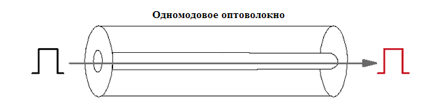
I think it is clear from the name that this cable transmits only one light carrier signal. The core is much smaller than the multimode cable. And if the core is smaller, then, and, accordingly, the attenuation of such a signal will be less. Do not need to use a large number of repeaters, which will save. And given that it transmits 10 km, the savings will be substantial. If for a multimode cable the light source served as an LED, then for single-mode cables they use a laser, since it projects a more powerful beam of light.
It's time to compare. So which is better? There is no definite answer. The technical parameters are better single-mode, but it is much more expensive to do in price and maintenance. The cables themselves are almost equal in price, but the equipment used for single-mode cables is much more expensive. If you have 2 buildings that are 200 meters away from each other, then why buy more expensive equipment and lay a single-mode cable, when a multimode connection can cope with this task and cost much less. Another situation, when there is a large distance between two points, it is more expedient, of course, to lay a single-mode cable. Despite the high cost of active equipment, additional equipment is not needed, and if it is needed, it is not in such quantity. So the choice depends on the situation and finances.
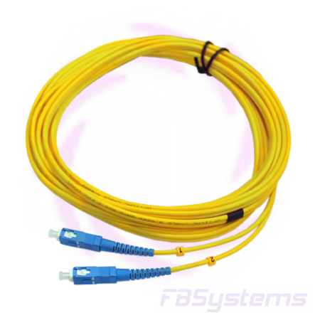
This is what a modern fiber-optic cable with a connector looks like.
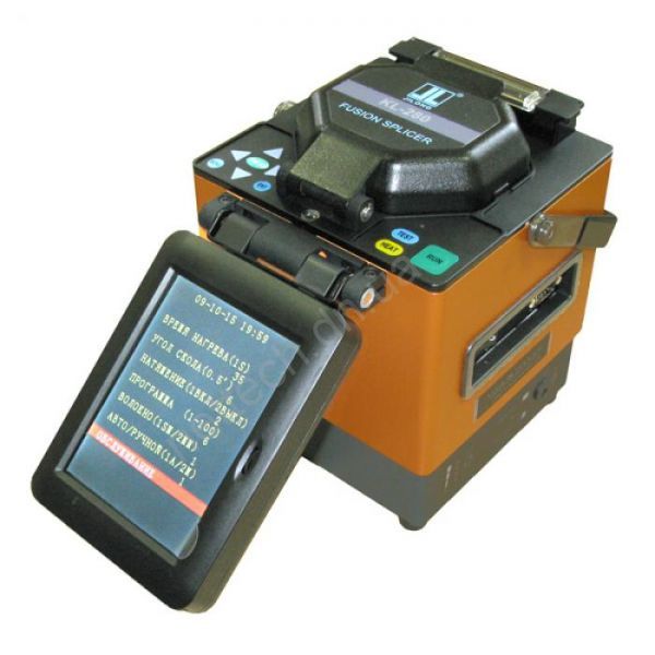
If a crimper was enough to connect the twisted pair, then with the optical fiber it is harder. For its connection requires a welding machine.
Another cable worth mentioning is serial or serial. Cable for connecting 2 network devices. The point-to-point technology itself is very old, but nonetheless it still occurs and many devices work with it. The main requirement for the device is the support of the data link layer (that is, layer 2 on the OSI model), since the devices must decide which one is the main one. The main device is needed so that it dictates the speed of the channel. For this, 2 concepts of DCE (Data Communication Equipment) and DTE (Data Terminal Equipment) were introduced. Typically, a DCE device is a provider, and a DTE router on a local network. Connectors to this type of cable was also a huge amount. I'll give you the latest look that Cisco uses.

And finally, I'll tell you about the console (rollover)cable. If previous cables were used to transfer data between devices, then this cable is used to configure network devices. Such as switches, routers and other devices that have a console interface. Here is one of them:
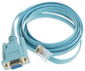
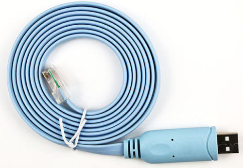
The 8P8C (RJ-45) connector connects to the device, and the COM connector (wide) to the computer. But given that COM ports are becoming extinct and rarely seen on modern computers, more modern ones began to appear on the market. For example, the sample is below, where the COM connector is replaced with USB.
That came to an end the 4th part. For a long time I wrote it. The session began and there was a catastrophic lack of time. At best, he wrote several sentences a day. And there were days when I sat down to write, but in my head I could not connect two sentences and close the lid of the laptop. Thanks to everyone who waited and a special thank you to those guys who were interested in the release of the article, which strongly motivated and nudged. Read on health!
Source: https://habr.com/ru/post/312340/
All Articles