Usage Chart in Software Development
 For several years now, as an analyst, I have been using the use cases (SI) and SI diagrams to document requirements quite widely in my work. In general, use cases have different names. They are called use cases, use cases, and even use cases. I remember how in the mid-2000s, on some analytical resources, there was a heated discussion on how to translate the term use case into Russian. It was then that the terrible word "precedent" appeared, and even more, some comrades argued that the Russian language is flawed and does not allow to convey all the subtleties of the use case concept. But as time has shown, the concept of a use case (or use case) is quite appropriate for itself and quite pleasant to hear.
Having only positive experience with SI, I was very surprised when, when communicating with colleagues from other companies, I learned that they did not use them and, moreover, they even tried to convince me that drawing little men, ovals and sticks between them was empty waste of time. That's why I decided to share my experience and demonstrate how SI diagrams help me in my work.
First, what is a usage scenario? The usage scenario is a coherent story about the behavior of the system when it interacts with someone (or something) from the external environment. Someone or something may be a user of the system, it may be some kind of information system or device. And this someone or something is called the Actor (DL). And the use scenario itself is a sequence of steps that describe the actions of the DL and the response of the system to them.
For example, a registration script on a website might look like this:
')
- The user gives the command to register.
- The site displays a registration form.
- The user fills in the form and confirms the registration.
- The site confirms the correctness of filling out the form.
- The site sends an email to the specified e-mail with a request to confirm registration.
- The user confirms the registration.
- Site registers user.
As you can see, the actions of the user and the system alternate with each other, they seem to play the ball, making passes to each other. You can read more about SI here: ru.wikipedia.org/wiki/Service_use script
But a corrosive reader can rightly argue that such a scenario cannot be given to the development. And he will be right! We are now looking at the system from a height, probably a 5-storey building, when the general behavior is already clear, but there are no detailed requirements yet. Therefore, the use case should, at a minimum, be supplemented with alternative threads of execution (what is presented above is called the main thread and describes the actions of the system when everything goes as it should). Alternative flows are flows that describe the system's reaction to erroneous user actions or exceptions, or alternative user actions if he chooses, for example, to register using an account on a social network. You can also add a use case document with user interface details, data validation rules, various business rules and error messages. But non-functional requirements are usually described in a separate document, as they are usually applicable to the entire system, rather than to specific SIs.
If, however, to rise even higher and look at the system from a greater “height”, then it will look like a set of services provided by the system to the user (usage scenarios can also be considered as high-level system requirements). Here we come to the idea that it would be nice to visualize these requirements, and the corresponding UML diagram is great for this: use case diagram. A slice of the chart is shown below. It consists of actors, usage scenarios, and various links between them.
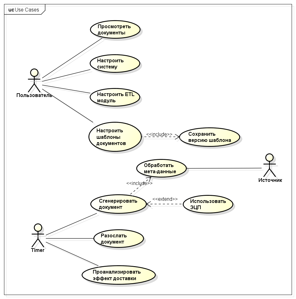
For developers and testers, at first glance, it is even less useful than the use cases themselves. But after all, it is intended for another!
The SI diagram is usually drawn by the analyst at the very beginning of the project in order to cover in broad strokes the entire planned functionality of the project and coordinate it with the customer. And after that, each SI is already detailed with steps and detailed requirements. SI help to look at the system from the point of view of the services provided by the system and not to dig in in particular.
I usually use the SI diagram for the following tasks:
- Evaluation of the complexity of the project;
- Scheduling work;
- Identify missed requirements;
- "Table of Contents" for project documents.
Let's see how SI helps to solve these problems.
Evaluation of the complexity of the project
As experience and practice show, the assessment is obtained the more precisely, the more detailed the list of upcoming works. Indeed, the task of “writing an article” is much more difficult to assess than the task of “finding 5 pictures for illustrations”. So, use cases are the first iteration of the breakdown of the system into separate elements. Moreover, these elements have good connectivity (in this case, functional) and can be evaluated separately from each other. If this is not enough, then each SI can already be decomposed into main / alternative streams or even tasks that need to be performed by the programmer to implement a separate scenario.
Here, the ability to reuse previously created artifacts is also quite often manifested. For example, if the system requires user registration functionality, then plus / minus it will work in the same way in many systems, which, when evaluated, immediately reduces the degree of uncertainty.
There is even a special SI-based assessment method - Use Case Points . In this case, the actors and scenarios are singled out, their complexity is determined according to certain rules, some correction factors are set that take into account the professionalism of the team and the complexity of the subject area, and a finished assessment appears at the output. That is, in the assessment, ideally, do not even need to attract developers and testers.
Scheduling work
In projects with a fixed budget, successive stages of design, development, and testing are usually clearly distinguished (as in the waterfall model). But in reality, testing already begins partly before the design stage is completed, since testers will connect to the review of the requirements developed and begin to write test design. And if it’s not difficult for an analyst and, say, an architect, to schedule work, since the activities of these roles begin with the start of the project, then it becomes more difficult to determine when and for what task it is necessary to connect testers with developers. Indeed, the input data for them are prepared and agreed documents with requirements. And again, SI is good for solving this problem. Since each scenario contains a complete description of a process, it is easier to coordinate them with customers and, accordingly, you can fairly accurately set the key points of agreement of requirements documents in the schedule. And already from these points to plan the work of the rest of the team.
Identify Missed Requirements
It’s not surprising that when a customer somehow voices the requirements for a future system, he’s in his description focuses precisely on useful functionality and doesn’t mention, for example, the system setup functions or user account management functions, although without them the system will not be complete work. Very often, after receiving such requirements, the team begins to carry out an assessment. In practice, I have had cases where the team immediately rushed into battle and evaluated what the customer described, leaving the unfounded, but, nevertheless, obligatory functions of the system behind.
There is also another situation when in the description of the system there are requirements that in the process of work, users must create some kind of entity. In the overwhelming majority of cases, all CRUD (Create, Read (or Retrieve decryption), Update, Delete) operations, which are also sometimes forgotten, are applicable to such entities. What is the use of the SI model here? And just in the graphical representation of the requirements. When the eye covers the entire picture, it is much easier to notice the missing elements than when the requirements are formulated in plain text.
"Table of Contents" for project documents
Very often, the customer asks together with the system to transfer a set of project documentation. In our company, we write project documentation in the form of usage scenarios. If the customer requires documents according to GOST, then all the same, use scripts are written first, and then GOST documents are formed on their basis.
We use at least two approaches to documentation: when each SI is described in a separate document, and when several SI related to the same subsystem are described in one document. Often this or that approach is determined based on the accepted process or customer habits.
It has already been said above that the first version of the list of use cases is already being formed at the stage of assessment and scheduling of work. In the future, this list can be supplemented and corrected, but with a certain degree of accuracy it is possible to agree with the customer about which documents the project team will provide.
Conclusion
After these explanations, I hope that the benefits of using the SI diagram have become clear. Despite its simplicity and even redundancy directly for developers, it gives a pretty good impetus to the start of any project. And it must be considered first of all in this vein. Alistair Coburn, in his book Modern Methods for Describing Functional Requirements for Systems, also writes that he sees no point in drawing rods and ovals, since they do not bring the reader closer to understanding how the system should work. But he, just, already speaks about the stage of detailed elaboration of requirements, which follows after defining a set of scenarios.
Source: https://habr.com/ru/post/312188/
All Articles