Three steps that will increase the noise of the digital converter
It is known that to control physical quantities, such as temperature, vibration, voltage, current, light, sound, etc. various sensors are used. Sensors can have both digital and analog outputs. On the one hand, if the output is digital, for example, with SPI or I2C interface, or a single TTL , then the sensor is immediately connected to the microcontroller. On the other hand, for a thermistor, photodiode, microphone, current shunt, voltage divider, etc., you need to convert the analog signal to digital. In this case, the task is somewhat more complicated, since The quality of the conversion depends on the developer.
There are a number of parameters that are determined by the converter chip, but otherwise everything depends on the wiring diagram. If we assume that the digit capacity, frequency band and sampling frequency of the converter are precisely known, then in some cases the connection circuit consists of resistors of the normalization circuit and possibly a driver with an ARC filter , a clock generator and a power source with the required voltage. This is far from a complete wiring diagram, but sufficient to evaluate the first three steps, which will negate the result of the work of an arbitrarily good converter chip.
For the evaluation of the subsequent results, it can be assumed that the input voltage range is 0..1V, the converter width is 24-bit, the effective conversion band is 20 kHz, and the temperature is room temperature.
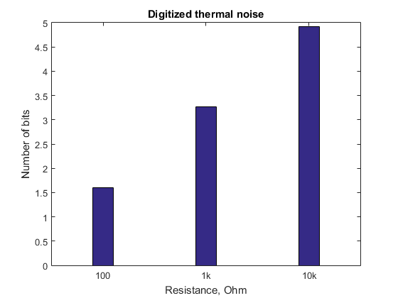
Step one is an increase in the “warm sound” of resistors connected in series with the input of the converter or its driver.
')
You can estimate the result in bits that will accurately convey all shades of room temperature using the thermal noise formula of a resistor . The script for Matlab will help in this important matter:
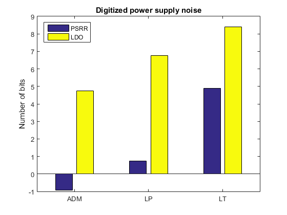
Step two is the reduction of passive and active filters in the converter power supply circuits.
For example, the article “Designing Second Stage Output Filters for Switching Power Supplies” states that an increase in the number of filter sections of a switching power supply makes sense to a noise level of about 1 mV. Further noise reduction is achieved through a linear voltage regulator.
In low-noise linear stabilizers, the level of noise suppression in power supply is 50..90 dB, and the intrinsic noise in the frequency range from 10 Hz to 100 kHz is 1.6 mKV. 20 mkV. You can use the following script to assess the effect of noise on the power supply:
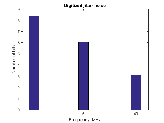
Step three - reducing the requirements for the clock generator.
It can be assumed that the relatively low maximum frequency of the signal helps reduce the requirements for the generator. To test this assumption, it suffices to use one of the many guides on the use of converters . As well as a special calculator , with which you can calculate the jitter of the generator for different frequencies.
To assess the effect of generator jitter on the final result, it is convenient to use the following script:
As you can see, even at relatively low sampling rates, the noise level due to generator jitter is a fairly serious problem. This is not a 10kΩ resistor, but an almost low-noise linear stabilizer. However, with increasing frequency, the situation improves dramatically. This gives reason to believe that a reasonable choice of the type of transducer can help reduce the level of noise. For example, at the same conversion rate, the sigma-delta converter is much less likely to make some noise, compared to the sequential approximation converter .
Of course, there are many more problems associated with the development of signal converters. But in my opinion, these three steps are a traditional design route (the picture has its own author, and I sincerely hope that he does not mind):

There are a number of parameters that are determined by the converter chip, but otherwise everything depends on the wiring diagram. If we assume that the digit capacity, frequency band and sampling frequency of the converter are precisely known, then in some cases the connection circuit consists of resistors of the normalization circuit and possibly a driver with an ARC filter , a clock generator and a power source with the required voltage. This is far from a complete wiring diagram, but sufficient to evaluate the first three steps, which will negate the result of the work of an arbitrarily good converter chip.
For the evaluation of the subsequent results, it can be assumed that the input voltage range is 0..1V, the converter width is 24-bit, the effective conversion band is 20 kHz, and the temperature is room temperature.
Step one is an increase in the “warm sound” of resistors connected in series with the input of the converter or its driver.
')
You can estimate the result in bits that will accurately convey all shades of room temperature using the thermal noise formula of a resistor . The script for Matlab will help in this important matter:
r = [100 1e3 1e4]'; % Resistance values. t = 24; % Ambient temperature. bw = 20e3; % Frequency bandwidth. u = 1; % Voltage range. N = 24; % Number of bits. %% Thermal noise u_t = 2*sqrt(physconst('Boltzmann')*(t+273.15)*r*bw); %% Number of bits according to thermal noise. thermal_bits = N+log2(u_t/u); %% Plot the result bar(log10(r),thermal_bits,0.2,'stacked'); title('Digitized thermal noise'); xlabel('Resistance, Ohm'), ylabel('Number of bits'); fig = gca; fig.XTickLabel = {'100','1k','10k'}; Step two is the reduction of passive and active filters in the converter power supply circuits.
For example, the article “Designing Second Stage Output Filters for Switching Power Supplies” states that an increase in the number of filter sections of a switching power supply makes sense to a noise level of about 1 mV. Further noise reduction is achieved through a linear voltage regulator.
In low-noise linear stabilizers, the level of noise suppression in power supply is 50..90 dB, and the intrinsic noise in the frequency range from 10 Hz to 100 kHz is 1.6 mKV. 20 mkV. You can use the following script to assess the effect of noise on the power supply:
N = 24; % Number of bits. dcdc_noise = 1e-3; % Output noise of the switching converter. ldo_noise = [1.6e-6 6.5e-6 20e-6]'; % Output noise of the LDO. ldo_psrr = [90 80 55]'; % PSRR of the LDO. %% Number of bits according to LDO noise ldo_noise_bits = N+log2(ldo_noise); %% Number of bits according to LDO PSRR ldo_psrr_bits = N+log2(dcdc_noise./db2mag(ldo_psrr)); %% Plot the result bar([ldo_psrr_bits ldo_noise_bits],'grouped'), title('Digitized power supply noise'); legend('PSRR','LDO','Location','northwest'); ylabel('Number of bits'); fig = gca; fig.XTickLabel = {'ADM','LP','LT'}; Step three - reducing the requirements for the clock generator.
It can be assumed that the relatively low maximum frequency of the signal helps reduce the requirements for the generator. To test this assumption, it suffices to use one of the many guides on the use of converters . As well as a special calculator , with which you can calculate the jitter of the generator for different frequencies.
To assess the effect of generator jitter on the final result, it is convenient to use the following script:
bw = 20e3; % Frequency bandwidth from previous step. N = 24; % Number of bits from previous step. fd = [1e6 6e6 40e6]; % Sampling frequency. tjrms = [130e-12 26e-12 3.3e-12]'; % Jitter in RMS seconds vs fd. %% Number of bits according to TJrms. tj_noise_bits = N + log2(7.69*bw*tjrms); %% Plot the result bar(log10(fd),tj_noise_bits,0.2,'stacked'); title('Digitized jitter noise'); xlabel('Frequency, MHz'), ylabel('Number of bits'); fig = gca; fig.XTick = log10(fd); fig.XTickLabel = {'1','6','40'}; As you can see, even at relatively low sampling rates, the noise level due to generator jitter is a fairly serious problem. This is not a 10kΩ resistor, but an almost low-noise linear stabilizer. However, with increasing frequency, the situation improves dramatically. This gives reason to believe that a reasonable choice of the type of transducer can help reduce the level of noise. For example, at the same conversion rate, the sigma-delta converter is much less likely to make some noise, compared to the sequential approximation converter .
Of course, there are many more problems associated with the development of signal converters. But in my opinion, these three steps are a traditional design route (the picture has its own author, and I sincerely hope that he does not mind):
Source: https://habr.com/ru/post/311278/
All Articles