Creating Babylon.js and WebGL based shaders: theory and examples
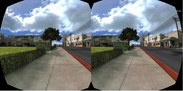
During their report on the second day of the Build 2014 conference, Microsoft evangelists Steven Guggenheimer and John Shevchuk spoke about the implementation of Babylon.js support for Oculus Rift. One of the key points of their demonstration was the mention of the lens imitation technology developed by us:
I also attended the report by Frank Olivier and Ben Constable on the use of graphics in IE using Babylon.js.
These reports reminded me of one question that I was often asked about Babylon.js: “What do you mean by shaders?” I decided to devote a whole article to this question to explain the principle of shaders and give some examples of their basic types.
This translation is part of a series of articles for developers from Microsoft.
')
Before we begin our experiences, we need to understand how everything functions.
Working with hardware accelerated 3D graphics, we are dealing with two different processors: the central (CPU) and the graphics (GPU). A graphics processor is just a form of highly specialized CPU.
A GPU is a state machine tuned by a CPU. For example, it is the CPU that instructs the GPU to display lines instead of triangles, turn on transparency, and so on.
Once all the states have been configured, the CPU will determine what needs to be rendered based on two main components: geometry, which is calculated based on a list of points or vertices (stored in an array called vertex buffer), and a list of indices — faces or triangles that are stored in the index buffer.
Finally, the CPU will determine how to render the geometry, and specifically for this will set the shaders for the GPU. Shaders are a piece of code executed by the GPU for all vertices and pixels that need to be rendered.
A vertex is a kind of point in 3D space (as opposed to a point in 2D space).
There are 2 types of shaders: vertex and pixel (fragment) shaders.
Graphic pipeline
Before going directly to the shaders, we will make another small digression. To display pixels, the GPU receives geometry data from the CPU.
With the help of an index buffer containing a list of vertex indices, 3 vertices are combined into a triangle. Each entry in the index buffer corresponds to the vertex number in the vertex buffer (this avoids duplicate vertices).
For example, the index buffer in the example below is a list of two faces: [1 2 3 1 3 4]. The first face contains vertices 1, 2, and 3. The second face contains vertices 1, 3, and 4. Thus, in this case, the geometry consists of four vertices:

The vertex shader is executed at each vertex of the triangle. The main purpose of the vertex shader is to display a pixel for each vertex (that is, to perform a projection of the 3D vertex on a 2D screen).

Using these 3 pixels (defining parameters of a 2D triangle on the screen), the GPU will analyze all pixel-related values (at least its position) and apply a pixel shader to generate a color for each pixel of the triangle.

The same is done for all faces in the index buffer.
The GPU is very efficient when performing parallel processes and therefore can easily process multiple faces simultaneously, while achieving high performance.
GLSL
As mentioned earlier, for rendering triangles the GPU will need 2 shaders: vertex and pixel. Both are written in a special language called GLSL (Graphics Library Shader Language), which is a bit like C.
Especially for Internet Explorer 11, we developed a compiler that converts GLSL to HLSL (High Level Shader Language) - the shader language of DirectX 11. This allowed us to increase the security of the shader code:

Here is an example of a simple vertex shader:
Vertex Shader Structure
The vertex shader contains the following elements:
As can be seen from the example above, there is nothing complicated in the vertex shader. It generates a system variable (starts with gl_) called gl_position to determine the position of a particular pixel, and also sets a varying variable called vUV.
Magic at the heart of matrices
The matrix in our shader is called worldViewProjection. It projects the position of the vertex into the gl_position variable. But how do we get the value of this matrix? Since this is a uniform variable, we need to define it on the CPU side (using JavaScript).
This is a difficult to understand aspect of working with 3D graphics. You need a good understanding of complex mathematical calculations (or use a 3D engine like Babylon.js, which we will talk about later).
The worldViewProjection matrix consists of three separate matrices:

The result is a matrix that allows you to convert 3D vertices to 2D pixels, taking into account the position of the viewpoint and everything related to the position, scale and rotation of the current object.
The task of the 3D designer is to create this matrix and maintain the relevance of its data.
And again shaders
After the vertex shader runs on each vertex (i.e., 3 times), we get 3 pixels with the correct vUV and gl_position value. Next, the GPU will transfer these values to each pixel inside the triangle formed by the three main pixels.
Then a pixel shader will be applied to each pixel:
The structure of the pixel (or fragment) shader
In its structure, the pixel shader is similar to the vertex one:
This pixel shader is very simple: it reads the texture color using the texture coordinates from the vertex shader (which, in turn, got them from the vertex).
That's what happened in the end. Rendering is performed in real time; You can move the sphere with the mouse.
To get this result, you need to work carefully with the code WebGL. Of course, WebGL is a very powerful API. But it is low-level, so you have to do everything yourself: from creating a buffer to determining the structure of the vertices. You will also need to perform many mathematical calculations, set up states, control texture loading, and so on.
I know what you thought: “Shaders are, of course, cool, but I don’t want to understand all the intricacies of WebGL and independently do all the calculations.”
No problem! That is why we created Babylon.js.
Here’s what the code for the same realm looks like in Babylon.js. First you need a simple web page:
Shaders here are set by script tags. In Babylon.js, they can also be specified in separate .fx files.
Babylon.js is available for download at the link here or in our repository on GitHub. To access the BABYLON.StandardMaterial object, you need version 1.11 or higher.
Finally, the main JavaScript code looks like this:
"Use strict";
As you can see, I use BABYLON.ShaderMaterial to get rid of the need to compile, link, or manipulate shaders.
When creating the BABYLON.ShaderMaterial object, you need to specify the DOM element used to store the shaders or the base name of the files in which the shaders are located. For the second option, you will also need to create a file for each shader using the following naming principle: basename.vertex.fx and basename.fragment.fx. Then you will need to create a material like this:
You must also specify the names of any used attributes and uniform variables. You can then directly set the values of uniform variables and samplers using the setTexture, setFloat, setFloats, setColor3, setColor4, setVector2, setVector3, setVector4, and setMatrix functions.
Pretty simple, right?
Remember the worldViewProjection matrix? With Babylon.js and BABYLON.ShaderMaterial you don’t have to worry about it. The BABYLON.ShaderMaterial object will calculate everything automatically, since we declare the matrix in the list of uniform variables.
The BABYLON.ShaderMaterial object can independently manage the following matrices:
No complicated calculations. For example, with each execution of sphere.rotation.y + = 0.05, the world matrix of this sphere is generated and transmitted to the GPU.
We will go even further and create a page where you can dynamically edit the shaders and watch the result in real time. To do this, we need the old code, as well as the BABYLON.ShaderMaterial object for compiling and executing the created shaders.
I used a code editor for CYOS called ACE. It is incredibly convenient and features a syntax highlighting feature.
In the Templates field, you can select pre-installed shaders, we will talk about them a little later. You can also change the 3D object used to preview the shaders in the Meshes field.
The Compile button is used to create a new BABYLON.ShaderMaterial object from shaders. Here is its code:
Suspiciously simple, right? So, it remains only to get 3 pre-computed matrices: world, worldView and worldViewProjection. The vertex data will contain the position, normal, and texture coordinates. Also the following 2 textures will be loaded:

amiga.jpg

ref.jpg
And this is the renderLoop, where I update 2 uniform variables:
In addition, CYOS is now available for Windows Phone due to our work for Windows Phone 8.1:

Basic
Let's start with the basic shader in CYOS. We have already considered something similar. This shader calculates gl_position and uses texture coordinates to get the color for each pixel.
To calculate the position of a pixel, you need the worldViewProjection matrix and the position of the vertex:
The texture coordinates (uv) are transferred to the pixel shader unchanged.
Pay attention to the first line: precision mediump float; - it must be added to the vertex and pixel shader to work properly in Chrome. It is responsible for ensuring that high precision numbers are not used to improve performance.
With a pixel shader, everything is even simpler: you just need to use the texture coordinates and get the texture color:
As was seen earlier, the uniform-variable textureSampler is filled with an amiga texture, so the result looks like this:

Black and white
Let's move on to the second shader, black and white. It will use the parameters of the previous one, but in black and white rendering. Leave the same settings as the vertex shader and make small changes to the pixel code.
The easiest way to achieve this effect is to take just one component, for example, as shown below:
We used .ggg instead of .rgb (in computer graphics this operation is called swizzle). But if you want to get a real black and white effect, it is best to calculate the relative brightness, which takes into account all the components of the color:
Scalar product is calculated as follows:
In our case:
(these values are calculated taking into account that the human eye is more sensitive to green)

Cell shading
Next on the list is a shader filled with cells, it's a bit more complicated.
In this case, we need to add the position of the vertex and the normal to the vertex in the pixel shader. The vertex shader will look like this:
Learn that the position data of the vertex and the normal to the vertex are transmitted unchanged, so we also need to apply the world matrix to take into account the rotation of the object.
Here is what a pixel shader will look like:
This shader is designed to simulate light, therefore, in order not to calculate smooth shading over the entire surface of the object, we will calculate the light intensity based on several brightness thresholds. For example, if the intensity is from 1 (maximum) to 0.95, the color of the object, taken from the texture, will be superimposed directly, without changes. If the intensity is from 0.95 to 0.5, a factor of 0.8 will be applied to the color value and so on.
As a result, the process of creating such a shader can be divided into 4 steps:
The intensity of light incident on a pixel depends on the angle between the normal to the top and the direction of the light.
As a result, we get something similar to the multiplier effect:

Phong
We already used the Phong algorithm in the previous example. Now consider it more.
With the vertex shader, everything will be pretty simple, since most of the work will be in the pixel one:
According to the algorithm, it is necessary to calculate the diffuse and specular components using the directions of light and the normal to the vertex:
In the previous example, we used only the diffuse component, so it remains only to add a mirror. This picture from a Wikipedia article explains the principle of shader operation:

Posted by: Brad Smith aka Rainwarrior
Result:

Discard
For this type of shader, I would like to introduce a new concept: the discard keyword. Such a shader will ignore any pixel that is not red, resulting in an illusion of a hollow object.
The vertex shader will be the same in this case as for the base shader:
The pixel shader will check the color of each pixel and use the discard keyword when, for example, the value of the green component is too large:
The result looks quite funny:

Wave
Perhaps we have already played enough with pixel shaders. Now I would like to pay more attention to vertex shaders.
For this example, we need a pixel shader with Phong shading.
In the vertex shader, we use a uniform variable called time to get dynamic values. This variable will generate a wave in which the vertices will change their position:
The sine is multiplied by position.y, and this gives the following result:

Spherical Environment Mapping
This beautiful tutor inspired us to create this shader. I recommend to familiarize yourself with it, and then see the Wave shader in CYOS.

Fresnel
And finally, my favorite shader, Fresnel. It changes intensity depending on the angle between the viewing direction and the normal to the top.
The vertex shader here is exactly the same as the shader with the cell fill, and we can easily calculate the Fresnel reflection value required for the pixel shader (you can use the normals and camera positions to determine the viewing direction):

Your shader
I think now you are ready to create your own shader. Feel free to share the results of experiments in the comments below.
Here are some additional links for those who want to learn more about the material:
And a few more of my articles on the same topic:
As well as JavaScript lessons from our team:
And, of course, you can always use some of our free tools to optimize your web experience: the Visual Studio Community , the Azure trial version and the cross-browser testing tools for Mac, Linux or Windows.
I also attended the report by Frank Olivier and Ben Constable on the use of graphics in IE using Babylon.js.
These reports reminded me of one question that I was often asked about Babylon.js: “What do you mean by shaders?” I decided to devote a whole article to this question to explain the principle of shaders and give some examples of their basic types.
This translation is part of a series of articles for developers from Microsoft.
')
Theory
Before we begin our experiences, we need to understand how everything functions.
Working with hardware accelerated 3D graphics, we are dealing with two different processors: the central (CPU) and the graphics (GPU). A graphics processor is just a form of highly specialized CPU.
A GPU is a state machine tuned by a CPU. For example, it is the CPU that instructs the GPU to display lines instead of triangles, turn on transparency, and so on.
Once all the states have been configured, the CPU will determine what needs to be rendered based on two main components: geometry, which is calculated based on a list of points or vertices (stored in an array called vertex buffer), and a list of indices — faces or triangles that are stored in the index buffer.
Finally, the CPU will determine how to render the geometry, and specifically for this will set the shaders for the GPU. Shaders are a piece of code executed by the GPU for all vertices and pixels that need to be rendered.
A vertex is a kind of point in 3D space (as opposed to a point in 2D space).
There are 2 types of shaders: vertex and pixel (fragment) shaders.
Graphic pipeline
Before going directly to the shaders, we will make another small digression. To display pixels, the GPU receives geometry data from the CPU.
With the help of an index buffer containing a list of vertex indices, 3 vertices are combined into a triangle. Each entry in the index buffer corresponds to the vertex number in the vertex buffer (this avoids duplicate vertices).
For example, the index buffer in the example below is a list of two faces: [1 2 3 1 3 4]. The first face contains vertices 1, 2, and 3. The second face contains vertices 1, 3, and 4. Thus, in this case, the geometry consists of four vertices:
Vertex - Top
Vertex Buffer - Vertex Buffer
Index Bufer - Index Buffer
Face - Edge
The vertex shader is executed at each vertex of the triangle. The main purpose of the vertex shader is to display a pixel for each vertex (that is, to perform a projection of the 3D vertex on a 2D screen).
Using these 3 pixels (defining parameters of a 2D triangle on the screen), the GPU will analyze all pixel-related values (at least its position) and apply a pixel shader to generate a color for each pixel of the triangle.
The same is done for all faces in the index buffer.
The GPU is very efficient when performing parallel processes and therefore can easily process multiple faces simultaneously, while achieving high performance.
GLSL
As mentioned earlier, for rendering triangles the GPU will need 2 shaders: vertex and pixel. Both are written in a special language called GLSL (Graphics Library Shader Language), which is a bit like C.
Especially for Internet Explorer 11, we developed a compiler that converts GLSL to HLSL (High Level Shader Language) - the shader language of DirectX 11. This allowed us to increase the security of the shader code:
Here is an example of a simple vertex shader:
precision highp float; // Attributes attribute vec3 position; attribute vec2 uv; // Uniforms uniform mat4 worldViewProjection; // Varying varying vec2 vUV; void main(void) { gl_Position = worldViewProjection * vec4(position, 1.0); vUV = uv; } Vertex Shader Structure
The vertex shader contains the following elements:
- Attributes : The attribute defines a portion of a vertex. By default, a vertex must have at least position data (vector3: x, y, z). But you, as a developer, can provide more data. For example, in the code above there is a vector2 called uv (texture coordinates, allowing us to apply a 2D texture to a 3D object).
- Uniform Variables: Determined by the CPU and used by the shader. The only uniform variable that we have in this case is the matrix used to project the position of the vertex (x, y, z) on the screen (x, y).
- Varying variables: These are the values that are created by the vertex shader and are passed to the pixel shader. In our case, the vertex shader will transfer the vUV value (a simple copy of uv) to the pixel shader. Consequently, texture coordinates and pixel position are determined here. The GPU will add these values, and the pixel shader will use them directly.
- main: The main () function is the code that runs in the GPU for each vertex. It should at least give a value for gl_position (the position of the current vertex on the screen).
As can be seen from the example above, there is nothing complicated in the vertex shader. It generates a system variable (starts with gl_) called gl_position to determine the position of a particular pixel, and also sets a varying variable called vUV.
Magic at the heart of matrices
The matrix in our shader is called worldViewProjection. It projects the position of the vertex into the gl_position variable. But how do we get the value of this matrix? Since this is a uniform variable, we need to define it on the CPU side (using JavaScript).
This is a difficult to understand aspect of working with 3D graphics. You need a good understanding of complex mathematical calculations (or use a 3D engine like Babylon.js, which we will talk about later).
The worldViewProjection matrix consists of three separate matrices:
The result is a matrix that allows you to convert 3D vertices to 2D pixels, taking into account the position of the viewpoint and everything related to the position, scale and rotation of the current object.
The task of the 3D designer is to create this matrix and maintain the relevance of its data.
And again shaders
After the vertex shader runs on each vertex (i.e., 3 times), we get 3 pixels with the correct vUV and gl_position value. Next, the GPU will transfer these values to each pixel inside the triangle formed by the three main pixels.
Then a pixel shader will be applied to each pixel:
precision highp float; varying vec2 vUV; uniform sampler2D textureSampler; void main(void) { gl_FragColor = texture2D(textureSampler, vUV); } The structure of the pixel (or fragment) shader
In its structure, the pixel shader is similar to the vertex one:
- Varying variables: These are the values that are created by the vertex shader and are passed to the pixel shader. In our case, the pixel shader will get the vUV value from the vertex shader.
- Uniform Variables: Determined by the CPU and used by the shader. The only uniform variable that we have in this case is a sampler that is needed to read texture colors.
- main: The main function is the code that runs in the GPU for each pixel. It should at least give a value for gl_FragColor (the color of the current pixel).
This pixel shader is very simple: it reads the texture color using the texture coordinates from the vertex shader (which, in turn, got them from the vertex).
That's what happened in the end. Rendering is performed in real time; You can move the sphere with the mouse.
To get this result, you need to work carefully with the code WebGL. Of course, WebGL is a very powerful API. But it is low-level, so you have to do everything yourself: from creating a buffer to determining the structure of the vertices. You will also need to perform many mathematical calculations, set up states, control texture loading, and so on.
Too hard? BABYLON.ShaderMaterial to the rescue
I know what you thought: “Shaders are, of course, cool, but I don’t want to understand all the intricacies of WebGL and independently do all the calculations.”
No problem! That is why we created Babylon.js.
Here’s what the code for the same realm looks like in Babylon.js. First you need a simple web page:
<!DOCTYPE html> <html> <head> <title>Babylon.js</title> <script src="Babylon.js"></script> <script type="application/vertexShader" id="vertexShaderCode"> precision highp float; // Attributes attribute vec3 position; attribute vec2 uv; // Uniforms uniform mat4 worldViewProjection; // Normal varying vec2 vUV; void main(void) { gl_Position = worldViewProjection * vec4(position, 1.0); vUV = uv; } </script> <script type="application/fragmentShader" id="fragmentShaderCode"> precision highp float; varying vec2 vUV; uniform sampler2D textureSampler; void main(void) { gl_FragColor = texture2D(textureSampler, vUV); } </script> <script src="index.js"></script> <style> html, body { width: 100%; height: 100%; padding: 0; margin: 0; overflow: hidden; margin: 0px; overflow: hidden; } #renderCanvas { width: 100%; height: 100%; touch-action: none; -ms-touch-action: none; } </style> </head> <body> <canvas id="renderCanvas"></canvas> </body> </html> Shaders here are set by script tags. In Babylon.js, they can also be specified in separate .fx files.
Babylon.js is available for download at the link here or in our repository on GitHub. To access the BABYLON.StandardMaterial object, you need version 1.11 or higher.
Finally, the main JavaScript code looks like this:
"Use strict";
document.addEventListener("DOMContentLoaded", startGame, false); function startGame() { if (BABYLON.Engine.isSupported()) { var canvas = document.getElementById("renderCanvas"); var engine = new BABYLON.Engine(canvas, false); var scene = new BABYLON.Scene(engine); var camera = new BABYLON.ArcRotateCamera("Camera", 0, Math.PI / 2, 10, BABYLON.Vector3.Zero(), scene); camera.attachControl(canvas); // Creating sphere var sphere = BABYLON.Mesh.CreateSphere("Sphere", 16, 5, scene); var amigaMaterial = new BABYLON.ShaderMaterial("amiga", scene, { vertexElement: "vertexShaderCode", fragmentElement: "fragmentShaderCode", }, { attributes: ["position", "uv"], uniforms: ["worldViewProjection"] }); amigaMaterial.setTexture("textureSampler", new BABYLON.Texture("amiga.jpg", scene)); sphere.material = amigaMaterial; engine.runRenderLoop(function () { sphere.rotation.y += 0.05; scene.render(); }); } }; As you can see, I use BABYLON.ShaderMaterial to get rid of the need to compile, link, or manipulate shaders.
When creating the BABYLON.ShaderMaterial object, you need to specify the DOM element used to store the shaders or the base name of the files in which the shaders are located. For the second option, you will also need to create a file for each shader using the following naming principle: basename.vertex.fx and basename.fragment.fx. Then you will need to create a material like this:
var cloudMaterial = new BABYLON.ShaderMaterial("cloud", scene, "./myShader", { attributes: ["position", "uv"], uniforms: ["worldViewProjection"] }); You must also specify the names of any used attributes and uniform variables. You can then directly set the values of uniform variables and samplers using the setTexture, setFloat, setFloats, setColor3, setColor4, setVector2, setVector3, setVector4, and setMatrix functions.
Pretty simple, right?
Remember the worldViewProjection matrix? With Babylon.js and BABYLON.ShaderMaterial you don’t have to worry about it. The BABYLON.ShaderMaterial object will calculate everything automatically, since we declare the matrix in the list of uniform variables.
The BABYLON.ShaderMaterial object can independently manage the following matrices:
- world;
- view;
- projection;
- worldView;
- worldViewProjection.
No complicated calculations. For example, with each execution of sphere.rotation.y + = 0.05, the world matrix of this sphere is generated and transmitted to the GPU.
CYOS: Build your own shader
We will go even further and create a page where you can dynamically edit the shaders and watch the result in real time. To do this, we need the old code, as well as the BABYLON.ShaderMaterial object for compiling and executing the created shaders.
I used a code editor for CYOS called ACE. It is incredibly convenient and features a syntax highlighting feature.
In the Templates field, you can select pre-installed shaders, we will talk about them a little later. You can also change the 3D object used to preview the shaders in the Meshes field.
The Compile button is used to create a new BABYLON.ShaderMaterial object from shaders. Here is its code:
// Compile shaderMaterial = new BABYLON.ShaderMaterial("shader", scene, { vertexElement: "vertexShaderCode", fragmentElement: "fragmentShaderCode", }, { attributes: ["position", "normal", "uv"], uniforms: ["world", "worldView", "worldViewProjection"] }); var refTexture = new BABYLON.Texture("ref.jpg", scene); refTexture.wrapU = BABYLON.Texture.CLAMP_ADDRESSMODE; refTexture.wrapV = BABYLON.Texture.CLAMP_ADDRESSMODE; var amigaTexture = new BABYLON.Texture("amiga.jpg", scene); shaderMaterial.setTexture("textureSampler", amigaTexture); shaderMaterial.setTexture("refSampler", refTexture); shaderMaterial.setFloat("time", 0); shaderMaterial.setVector3("cameraPosition", BABYLON.Vector3.Zero()); shaderMaterial.backFaceCulling = false; mesh.material = shaderMaterial; Suspiciously simple, right? So, it remains only to get 3 pre-computed matrices: world, worldView and worldViewProjection. The vertex data will contain the position, normal, and texture coordinates. Also the following 2 textures will be loaded:
amiga.jpg
ref.jpg
And this is the renderLoop, where I update 2 uniform variables:
- time variable - to get funny animations;
- variable cameraPosition - to get information about the position of the camera in the shaders (which is very useful when calculating the lighting);
engine.runRenderLoop(function () { mesh.rotation.y += 0.001; if (shaderMaterial) { shaderMaterial.setFloat("time", time); time += 0.02; shaderMaterial.setVector3("cameraPosition", camera.position); } scene.render(); }); In addition, CYOS is now available for Windows Phone due to our work for Windows Phone 8.1:
Basic
Let's start with the basic shader in CYOS. We have already considered something similar. This shader calculates gl_position and uses texture coordinates to get the color for each pixel.
To calculate the position of a pixel, you need the worldViewProjection matrix and the position of the vertex:
precision highp float; // Attributes attribute vec3 position; attribute vec2 uv; // Uniforms uniform mat4 worldViewProjection; // Varying varying vec2 vUV; void main(void) { gl_Position = worldViewProjection * vec4(position, 1.0); vUV = uv; } The texture coordinates (uv) are transferred to the pixel shader unchanged.
Pay attention to the first line: precision mediump float; - it must be added to the vertex and pixel shader to work properly in Chrome. It is responsible for ensuring that high precision numbers are not used to improve performance.
With a pixel shader, everything is even simpler: you just need to use the texture coordinates and get the texture color:
precision highp float; varying vec2 vUV; uniform sampler2D textureSampler; void main(void) { gl_FragColor = texture2D(textureSampler, vUV); } As was seen earlier, the uniform-variable textureSampler is filled with an amiga texture, so the result looks like this:
Black and white
Let's move on to the second shader, black and white. It will use the parameters of the previous one, but in black and white rendering. Leave the same settings as the vertex shader and make small changes to the pixel code.
The easiest way to achieve this effect is to take just one component, for example, as shown below:
precision highp float; varying vec2 vUV; uniform sampler2D textureSampler; void main(void) { gl_FragColor = vec4(texture2D(textureSampler, vUV).ggg, 1.0); } We used .ggg instead of .rgb (in computer graphics this operation is called swizzle). But if you want to get a real black and white effect, it is best to calculate the relative brightness, which takes into account all the components of the color:
precision highp float; varying vec2 vUV; uniform sampler2D textureSampler; void main(void) { float luminance = dot(texture2D(textureSampler, vUV).rgb, vec3(0.3, 0.59, 0.11)); gl_FragColor = vec4(luminance, luminance, luminance, 1.0); } Scalar product is calculated as follows:
result = v0.x * v1.x + v0.y * v1.y + v0.z * v1.z In our case:
luminance = r * 0.3 + g * 0.59 + b * 0.11 (these values are calculated taking into account that the human eye is more sensitive to green)
Cell shading
Next on the list is a shader filled with cells, it's a bit more complicated.
In this case, we need to add the position of the vertex and the normal to the vertex in the pixel shader. The vertex shader will look like this:
precision highp float; // Attributes attribute vec3 position; attribute vec3 normal; attribute vec2 uv; // Uniforms uniform mat4 world; uniform mat4 worldViewProjection; // Varying varying vec3 vPositionW; varying vec3 vNormalW; varying vec2 vUV; void main(void) { vec4 outPosition = worldViewProjection * vec4(position, 1.0); gl_Position = outPosition; vPositionW = vec3(world * vec4(position, 1.0)); vNormalW = normalize(vec3(world * vec4(normal, 0.0))); vUV = uv; } Learn that the position data of the vertex and the normal to the vertex are transmitted unchanged, so we also need to apply the world matrix to take into account the rotation of the object.
Here is what a pixel shader will look like:
precision highp float; // Lights varying vec3 vPositionW; varying vec3 vNormalW; varying vec2 vUV; // Refs uniform sampler2D textureSampler; void main(void) { float ToonThresholds[4]; ToonThresholds[0] = 0.95; ToonThresholds[1] = 0.5; ToonThresholds[2] = 0.2; ToonThresholds[3] = 0.03; float ToonBrightnessLevels[5]; ToonBrightnessLevels[0] = 1.0; ToonBrightnessLevels[1] = 0.8; ToonBrightnessLevels[2] = 0.6; ToonBrightnessLevels[3] = 0.35; ToonBrightnessLevels[4] = 0.2; vec3 vLightPosition = vec3(0, 20, 10); // Light vec3 lightVectorW = normalize(vLightPosition - vPositionW); // diffuse float ndl = max(0., dot(vNormalW, lightVectorW)); vec3 color = texture2D(textureSampler, vUV).rgb; if (ndl > ToonThresholds[0]) { color *= ToonBrightnessLevels[0]; } else if (ndl > ToonThresholds[1]) { color *= ToonBrightnessLevels[1]; } else if (ndl > ToonThresholds[2]) { color *= ToonBrightnessLevels[2]; } else if (ndl > ToonThresholds[3]) { color *= ToonBrightnessLevels[3]; } else { color *= ToonBrightnessLevels[4]; } gl_FragColor = vec4(color, 1.); } This shader is designed to simulate light, therefore, in order not to calculate smooth shading over the entire surface of the object, we will calculate the light intensity based on several brightness thresholds. For example, if the intensity is from 1 (maximum) to 0.95, the color of the object, taken from the texture, will be superimposed directly, without changes. If the intensity is from 0.95 to 0.5, a factor of 0.8 will be applied to the color value and so on.
As a result, the process of creating such a shader can be divided into 4 steps:
- First, we declare the brightness thresholds and constants for each degree of intensity.
- We calculate the illumination based on the Phong algorithm (based on the consideration that the light source does not move).
vec3 vLightPosition = vec3(0, 20, 10); // Light vec3 lightVectorW = normalize(vLightPosition - vPositionW); // diffuse float ndl = max(0., dot(vNormalW, lightVectorW)); The intensity of light incident on a pixel depends on the angle between the normal to the top and the direction of the light.
- Get the texture color for the pixel.
- Check the brightness threshold and apply a constant of the appropriate degree of intensity.
As a result, we get something similar to the multiplier effect:
Phong
We already used the Phong algorithm in the previous example. Now consider it more.
With the vertex shader, everything will be pretty simple, since most of the work will be in the pixel one:
precision highp float; // Attributes attribute vec3 position; attribute vec3 normal; attribute vec2 uv; // Uniforms uniform mat4 worldViewProjection; // Varying varying vec3 vPosition; varying vec3 vNormal; varying vec2 vUV; void main(void) { vec4 outPosition = worldViewProjection * vec4(position, 1.0); gl_Position = outPosition; vUV = uv; vPosition = position; vNormal = normal; } According to the algorithm, it is necessary to calculate the diffuse and specular components using the directions of light and the normal to the vertex:
precision highp float; // Varying varying vec3 vPosition; varying vec3 vNormal; varying vec2 vUV; // Uniforms uniform mat4 world; // Refs uniform vec3 cameraPosition; uniform sampler2D textureSampler; void main(void) { vec3 vLightPosition = vec3(0, 20, 10); // World values vec3 vPositionW = vec3(world * vec4(vPosition, 1.0)); vec3 vNormalW = normalize(vec3(world * vec4(vNormal, 0.0))); vec3 viewDirectionW = normalize(cameraPosition - vPositionW); // Light vec3 lightVectorW = normalize(vLightPosition - vPositionW); vec3 color = texture2D(textureSampler, vUV).rgb; // diffuse float ndl = max(0., dot(vNormalW, lightVectorW)); // Specular vec3 angleW = normalize(viewDirectionW + lightVectorW); float specComp = max(0., dot(vNormalW, angleW)); specComp = pow(specComp, max(1., 64.)) * 2.; gl_FragColor = vec4(color * ndl + vec3(specComp), 1.); } In the previous example, we used only the diffuse component, so it remains only to add a mirror. This picture from a Wikipedia article explains the principle of shader operation:
Posted by: Brad Smith aka Rainwarrior
Result:
Discard
For this type of shader, I would like to introduce a new concept: the discard keyword. Such a shader will ignore any pixel that is not red, resulting in an illusion of a hollow object.
The vertex shader will be the same in this case as for the base shader:
precision highp float; // Attributes attribute vec3 position; attribute vec3 normal; attribute vec2 uv; // Uniforms uniform mat4 worldViewProjection; // Varying varying vec2 vUV; void main(void) { gl_Position = worldViewProjection * vec4(position, 1.0); vUV = uv; } The pixel shader will check the color of each pixel and use the discard keyword when, for example, the value of the green component is too large:
precision highp float; varying vec2 vUV; // Refs uniform sampler2D textureSampler; void main(void) { vec3 color = texture2D(textureSampler, vUV).rgb; if (color.g > 0.5) { discard; } gl_FragColor = vec4(color, 1.); } The result looks quite funny:
Wave
Perhaps we have already played enough with pixel shaders. Now I would like to pay more attention to vertex shaders.
For this example, we need a pixel shader with Phong shading.
In the vertex shader, we use a uniform variable called time to get dynamic values. This variable will generate a wave in which the vertices will change their position:
precision highp float; // Attributes attribute vec3 position; attribute vec3 normal; attribute vec2 uv; // Uniforms uniform mat4 worldViewProjection; uniform float time; // Varying varying vec3 vPosition; varying vec3 vNormal; varying vec2 vUV; void main(void) { vec3 v = position; vx += sin(2.0 * position.y + (time)) * 0.5; gl_Position = worldViewProjection * vec4(v, 1.0); vPosition = position; vNormal = normal; vUV = uv; } The sine is multiplied by position.y, and this gives the following result:
Spherical Environment Mapping
This beautiful tutor inspired us to create this shader. I recommend to familiarize yourself with it, and then see the Wave shader in CYOS.
Fresnel
And finally, my favorite shader, Fresnel. It changes intensity depending on the angle between the viewing direction and the normal to the top.
The vertex shader here is exactly the same as the shader with the cell fill, and we can easily calculate the Fresnel reflection value required for the pixel shader (you can use the normals and camera positions to determine the viewing direction):
precision highp float; // Lights varying vec3 vPositionW; varying vec3 vNormalW; // Refs uniform vec3 cameraPosition; uniform sampler2D textureSampler; void main(void) { vec3 color = vec3(1., 1., 1.); vec3 viewDirectionW = normalize(cameraPosition - vPositionW); // Fresnel float fresnelTerm = dot(viewDirectionW, vNormalW); fresnelTerm = clamp(1.0 - fresnelTerm, 0., 1.); gl_FragColor = vec4(color * fresnelTerm, 1.); } Your shader
I think now you are ready to create your own shader. Feel free to share the results of experiments in the comments below.
Here are some additional links for those who want to learn more about the material:
» Babylon.js repository;
" Babylon.js forum;
» CYOS;
» GLSL article on Wikipedia;
» GLSL documentation.
And a few more of my articles on the same topic:
» Introduction to WebGL 3D with HTML5 and Babylon.JS;
Cutting Edge Graphics in HTML.
As well as JavaScript lessons from our team:
» Practical Performance Tips to Make your HTML / JavaScript Faster (a series of lessons in seven parts, covering many topics: from adaptive design to optimize performance and casual games);
» The Modern Web Platform Jump Start (basic HTML, CSS and JS);
» Developing Universal Windows App with HTML and JavaScript Jump Start (use already written JS code to create an application).
And, of course, you can always use some of our free tools to optimize your web experience: the Visual Studio Community , the Azure trial version and the cross-browser testing tools for Mac, Linux or Windows.
Source: https://habr.com/ru/post/311138/
All Articles