Getting started in STM32CubeMX. Part 1
Part 2
Part 3
I welcome the audience of Habr, and I want to bring to your attention the first post devoted to using the development environment STM32CubeMX, written for those who want to start learning STM32 from scratch.
')
I planned to write several posts, having considered several peripheral devices of the microcontroller and their configuration in STM32CubeMX. But these posts do not replace the company documentation and do not claim to be complete. They will consider only some, most, in my opinion, typical examples of the use of STM32 peripherals.
I hope this material will be useful to someone.
First, I will do a little explanation. To study this material, you will need a debug board with an STM32 microcontroller. I use the STM32F746G Discovery board, which today is one of the best, and, accordingly, expensive Discovery boards.
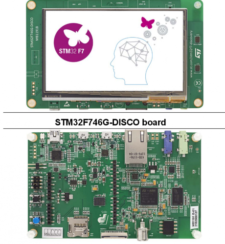
However, for the development of most of the material will be enough of any, even the most simple board on the STM32. I recommend the Discovery boards. they already contain the ST-Link debugger, and you only need a MiniUSB cable to work. To begin with, even the power supply is not needed, the board is powered through the same cable.
Naturally, when using a microcontroller other than the STM32F746G, it will be necessary to make corrections in projects for another clock frequency, another pinout, etc., but the essence remains the same. I recommend immediately download the documentation for your board with a schematic diagram and pdf on the microcontroller.
For further work it will be nice to have an oscilloscope, almost any, but you can start without it.
Again, anticipating questions about the purchase of the board, I bought on aliexpress, and it was much cheaper than from domestic sellers.
We also need STM32CubeMX itself (downloaded for free), and any IDE to work with the project on C and ST-Link support. There are many of them, there are commercial ones, there are free ones, and I will deliberately not give any names. Everyone chooses for himself.
First you need to download and install the STM32CubeMX. You can download it for free from st.com. I have to say, STM32CubeMX exists only in the Windows version. They write that it works fine under wine, I personally have not tried it.
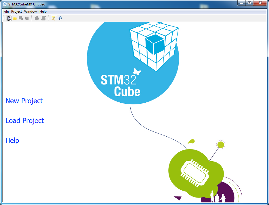
Go to the File / New Project, select the desired microcontroller. For this it is convenient to use filters in the upper part of the window.
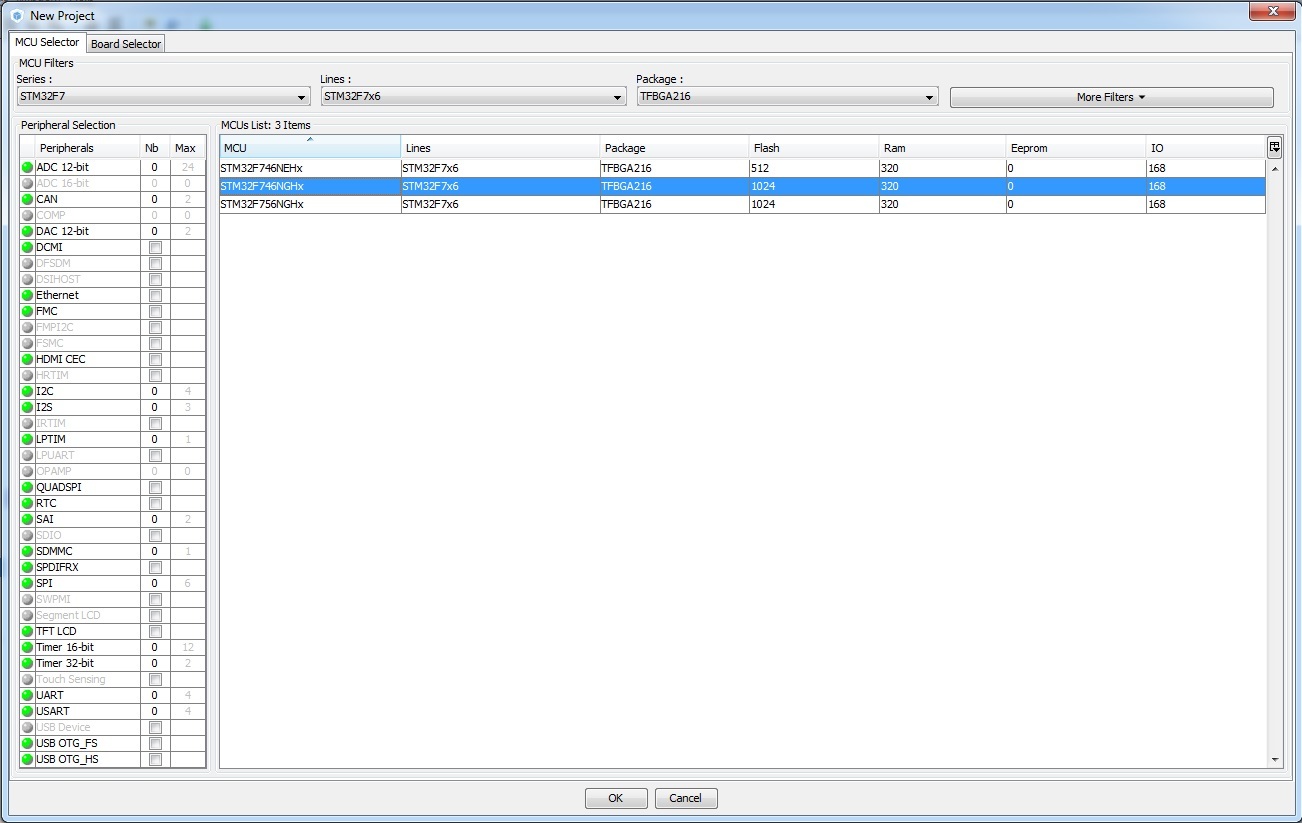
In our case, this is STM32F746NGHx.
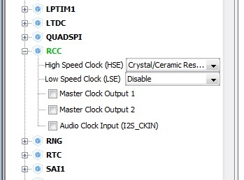
Next, set up the clock generator. In the Pinout tab, select work with external quartz:
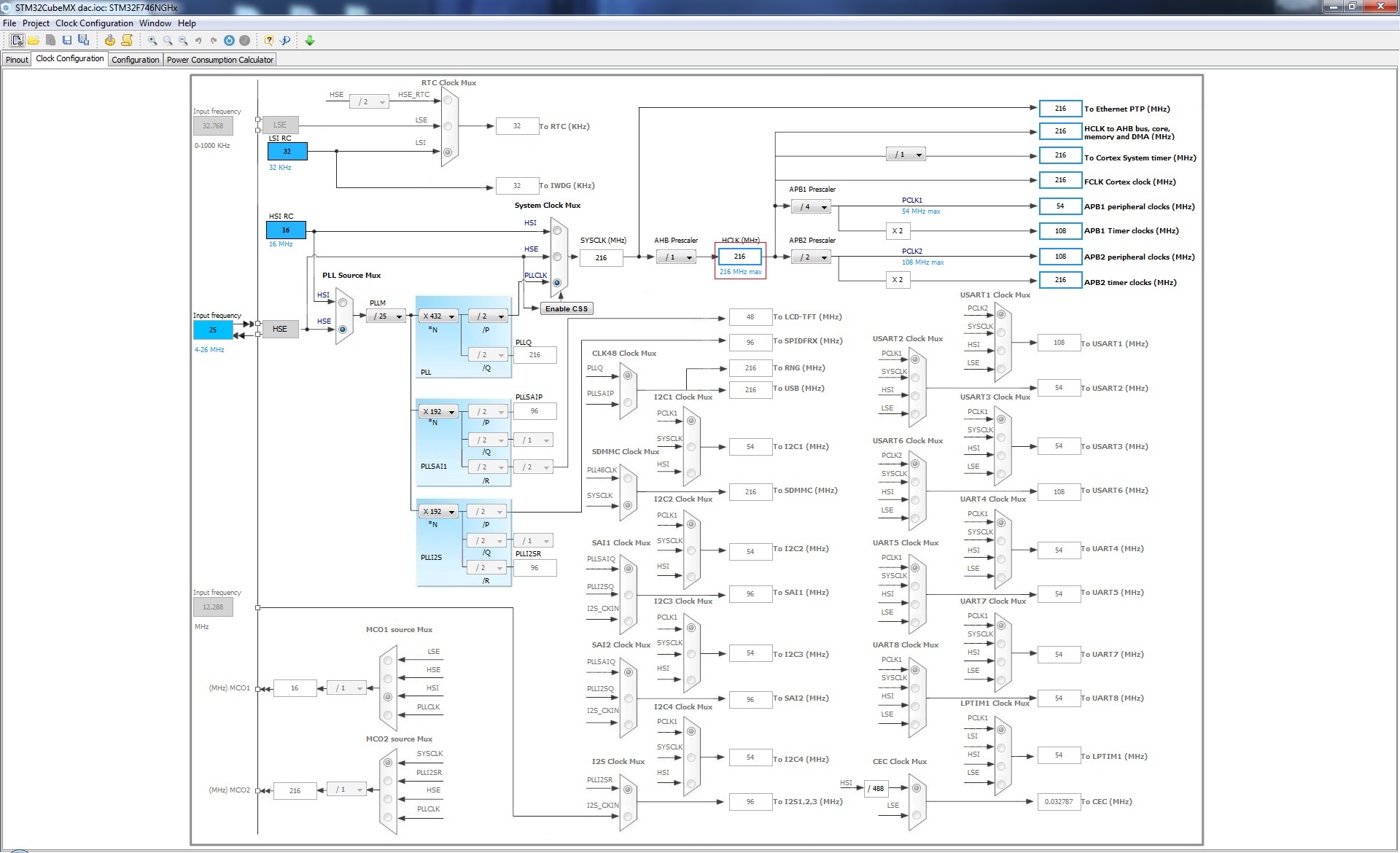
In the Clock Configuration tab, in the HCLK (MHz) field, we write 216. In response, we receive the message “No solution found using the current selected sources. Do you want to use other sources? ”We answer“ OK ”and select the HSE source in the PLL Source Mux multiplexer. The values of PLLM, PLLN and PLLP are set as shown in the figure. Check that HCLK = 216MHz.
Now you need to configure the GPIO that controls the LED. This is a PI1 port. On the Pinout tab, we find the output of PI1, click on it and set it to GPIO_Output.

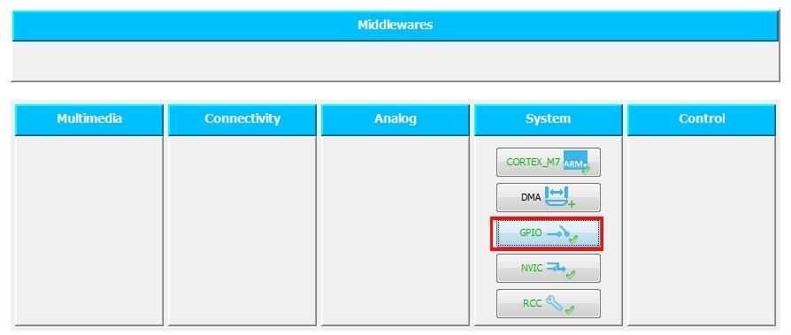
For further convenience, you can assign a pin name. It is not necessary to do this, but let's do it to make the code more readable. To do this, on the Configuration tab in the System column, click the GPIO button.
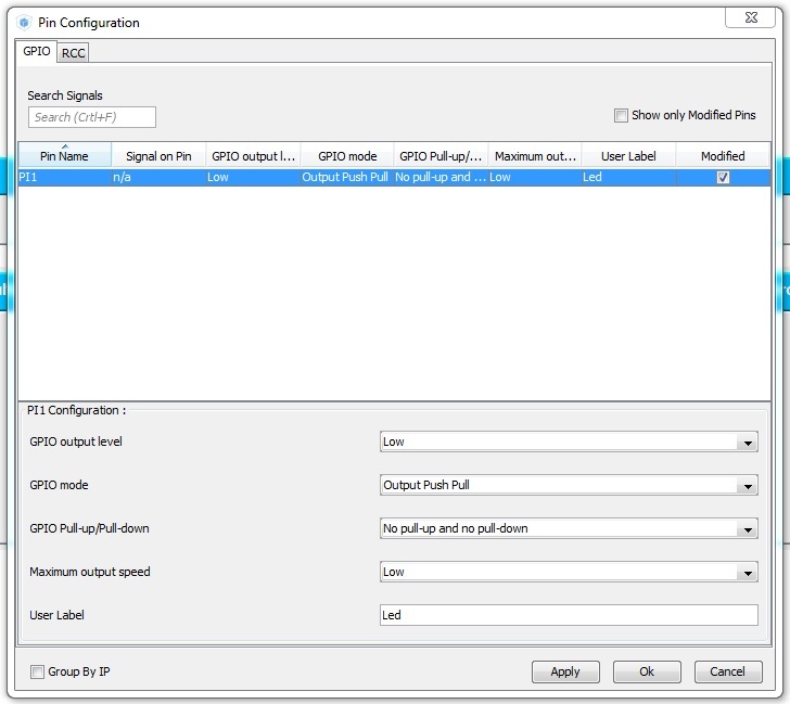
We fall into the window “Pin Configuration” and in the field User Label we write “Led”.
Now you can generate a code (Project / Generate Code). STM32CubeMX generates not only source code, but project files for a number of popular IDEs. Note that the code contains comments like:
You can only write your code in them, otherwise when you regenerate the source code, your code will be overwritten.
So, we find the while (1) loop in main () and write the following in it:
Now you can run the project. We connect the board and download the firmware. The LED on the board should flash at 1 Hz.
However, the above approach is not perfect. The HAL_Delay function contains an empty loop inside, and our program cannot do something else at this time. There are two ways to solve the problem: using interrupts and using a real-time operating system. I will write about the operating system another time, and we will learn to work with interruptions now.
Set the timer, for example TIM1. To do this, in the Pinout tab, select the clock source for this timer:
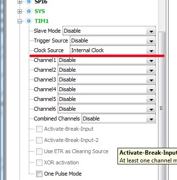
The source of clocking was the internal clock frequency of the periphery, which is 108MHz in our case. You can refine this value or change it by dividing the main clock frequency on the Clock Configuration tab.
Now go to the Configuration tab and configure the frequency of the timer. We press the TIM1 button and in the appeared window in the Parameter Settings tab we set the values Prescaler and Counter Period.
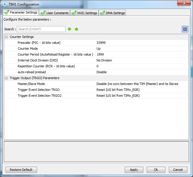
Note that the division factors must be reduced by 1 from the desired values. In fact, the timer interrupt frequency can be found by the formula:
In our case, the frequency will be equal to 216e6 / ((53999 + 1) * (1999 + 1)) = 2 Hz. The flashing frequency of the LED will be 1Hz, as in the previous example.
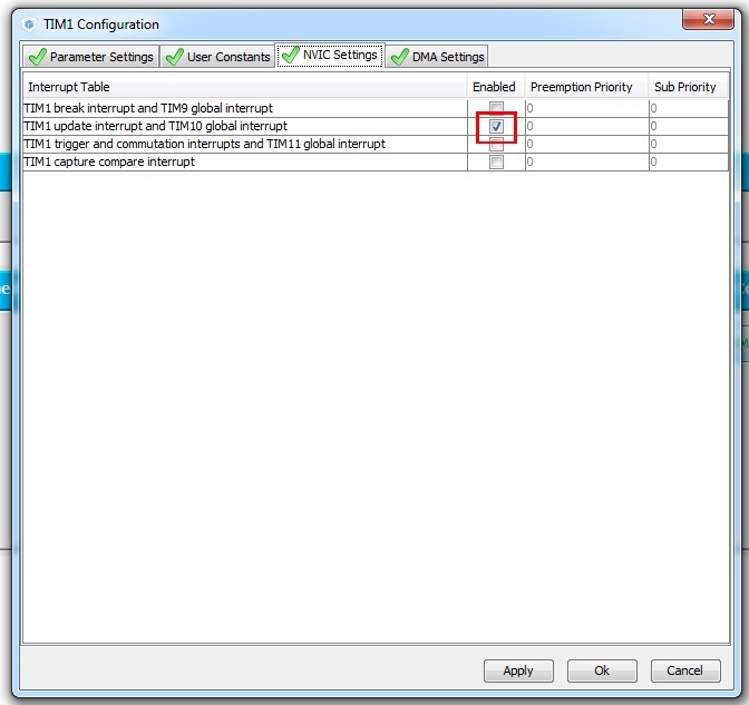
Now on the tab of the interrupt controller (NVIC Settings) you need to enable the TIM1 Update interrupt:
At this work in the STM32CubeMX finished, you can generate the code. In the source code, we first need to start the timer itself, and then insert an interrupt handler that will flash the LED:
Compile and fill the firmware. As expected, the LED flashes in the same way as in the previous example. However, since it is now interrupted, the processor is free to perform any other tasks.
On this I finish the first part. What is planned next? In the next part, I plan to describe the work with the built-in DAC and touch on the topic of DMA. As a small announcement: we will learn to generate such a beautiful sine wave:
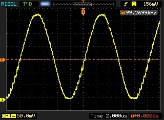
(This sinusoid is not very beautiful, in fact, but it will be better).
Future plans: work with USB controllers (for starters in VCP mode, virtual COM port), Ethernet controller, ADC, and, perhaps, we will touch on the use of FreeRTOS.
The examples given in the article were also implemented on the Nucleo F767ZI (microcontroller STM32F767ZI) board, in IDE Atollic TrueStudio. They can be downloaded here: https://github.com/arktur04/stm32-habr
Part 3
I welcome the audience of Habr, and I want to bring to your attention the first post devoted to using the development environment STM32CubeMX, written for those who want to start learning STM32 from scratch.
')
I planned to write several posts, having considered several peripheral devices of the microcontroller and their configuration in STM32CubeMX. But these posts do not replace the company documentation and do not claim to be complete. They will consider only some, most, in my opinion, typical examples of the use of STM32 peripherals.
I hope this material will be useful to someone.
1. Small introduction
First, I will do a little explanation. To study this material, you will need a debug board with an STM32 microcontroller. I use the STM32F746G Discovery board, which today is one of the best, and, accordingly, expensive Discovery boards.
However, for the development of most of the material will be enough of any, even the most simple board on the STM32. I recommend the Discovery boards. they already contain the ST-Link debugger, and you only need a MiniUSB cable to work. To begin with, even the power supply is not needed, the board is powered through the same cable.
Naturally, when using a microcontroller other than the STM32F746G, it will be necessary to make corrections in projects for another clock frequency, another pinout, etc., but the essence remains the same. I recommend immediately download the documentation for your board with a schematic diagram and pdf on the microcontroller.
For further work it will be nice to have an oscilloscope, almost any, but you can start without it.
Again, anticipating questions about the purchase of the board, I bought on aliexpress, and it was much cheaper than from domestic sellers.
We also need STM32CubeMX itself (downloaded for free), and any IDE to work with the project on C and ST-Link support. There are many of them, there are commercial ones, there are free ones, and I will deliberately not give any names. Everyone chooses for himself.
2. Hello World, or LED control
First you need to download and install the STM32CubeMX. You can download it for free from st.com. I have to say, STM32CubeMX exists only in the Windows version. They write that it works fine under wine, I personally have not tried it.
Go to the File / New Project, select the desired microcontroller. For this it is convenient to use filters in the upper part of the window.
In our case, this is STM32F746NGHx.
Next, set up the clock generator. In the Pinout tab, select work with external quartz:
In the Clock Configuration tab, in the HCLK (MHz) field, we write 216. In response, we receive the message “No solution found using the current selected sources. Do you want to use other sources? ”We answer“ OK ”and select the HSE source in the PLL Source Mux multiplexer. The values of PLLM, PLLN and PLLP are set as shown in the figure. Check that HCLK = 216MHz.
Now you need to configure the GPIO that controls the LED. This is a PI1 port. On the Pinout tab, we find the output of PI1, click on it and set it to GPIO_Output.
For further convenience, you can assign a pin name. It is not necessary to do this, but let's do it to make the code more readable. To do this, on the Configuration tab in the System column, click the GPIO button.
We fall into the window “Pin Configuration” and in the field User Label we write “Led”.
Now you can generate a code (Project / Generate Code). STM32CubeMX generates not only source code, but project files for a number of popular IDEs. Note that the code contains comments like:
/* USER CODE BEGIN 3 */ /* USER CODE END 3 */ You can only write your code in them, otherwise when you regenerate the source code, your code will be overwritten.
So, we find the while (1) loop in main () and write the following in it:
HAL_GPIO_TogglePin(Led_GPIO_Port, Led_Pin); //Toggle the state of pin HAL_Delay(500); // Now you can run the project. We connect the board and download the firmware. The LED on the board should flash at 1 Hz.
However, the above approach is not perfect. The HAL_Delay function contains an empty loop inside, and our program cannot do something else at this time. There are two ways to solve the problem: using interrupts and using a real-time operating system. I will write about the operating system another time, and we will learn to work with interruptions now.
3. Timer and interrupts
Set the timer, for example TIM1. To do this, in the Pinout tab, select the clock source for this timer:
The source of clocking was the internal clock frequency of the periphery, which is 108MHz in our case. You can refine this value or change it by dividing the main clock frequency on the Clock Configuration tab.
Now go to the Configuration tab and configure the frequency of the timer. We press the TIM1 button and in the appeared window in the Parameter Settings tab we set the values Prescaler and Counter Period.
Note that the division factors must be reduced by 1 from the desired values. In fact, the timer interrupt frequency can be found by the formula:
Update_event = TIM_CLK / ((PSC + 1) * (ARR + 1) * (RCR + 1))
In our case, the frequency will be equal to 216e6 / ((53999 + 1) * (1999 + 1)) = 2 Hz. The flashing frequency of the LED will be 1Hz, as in the previous example.
Now on the tab of the interrupt controller (NVIC Settings) you need to enable the TIM1 Update interrupt:
At this work in the STM32CubeMX finished, you can generate the code. In the source code, we first need to start the timer itself, and then insert an interrupt handler that will flash the LED:
/* USER CODE BEGIN 0 */ void HAL_TIM_PeriodElapsedCallback(TIM_HandleTypeDef *htim) { if (htim->Instance==TIM1) //check if the interrupt comes from TIM1 { HAL_GPIO_TogglePin(Led_GPIO_Port, Led_Pin); //Toggle the state of pin } } /* USER CODE END 0 */ int main(void) { ... /* USER CODE BEGIN 2 */ // HAL_TIM_Base_Start_IT(&htim1); /* USER CODE END 2 */ /* Infinite loop */ /* USER CODE BEGIN WHILE */ while (1) { /* USER CODE END WHILE */ /* USER CODE BEGIN 3 */ // , . } /* USER CODE END 3 */ } Compile and fill the firmware. As expected, the LED flashes in the same way as in the previous example. However, since it is now interrupted, the processor is free to perform any other tasks.
4. What's next?
On this I finish the first part. What is planned next? In the next part, I plan to describe the work with the built-in DAC and touch on the topic of DMA. As a small announcement: we will learn to generate such a beautiful sine wave:
(This sinusoid is not very beautiful, in fact, but it will be better).
Future plans: work with USB controllers (for starters in VCP mode, virtual COM port), Ethernet controller, ADC, and, perhaps, we will touch on the use of FreeRTOS.
PS
The examples given in the article were also implemented on the Nucleo F767ZI (microcontroller STM32F767ZI) board, in IDE Atollic TrueStudio. They can be downloaded here: https://github.com/arktur04/stm32-habr
Source: https://habr.com/ru/post/310742/
All Articles