How to stop being afraid and fall in love with mbed [Part 4]
We continue a series of publications devoted to the use of the ARM mbed environment for creating a prototype measuring device. Today we are talking about the basics of working with touch input.
Content of the publication cycle:
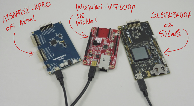
Following the results of the previous three articles, we received an mbed-project - a program that can be compiled into a working firmware for any debugging board with SPI and I2C interfaces and support in ARM mbed. The test subjects were debug boards from SLSTK3400A from Silicon Labs, ATSAMD21-XPRO from Atmel and WIZwiki-W7500P from Wiznet.
')
The implemented program performs two tasks so far - polling the temperature and relative humidity sensor HYT and outputting the measurement results to a Riverdi TFT-display. The project is available at developer.mbed.org .
Today we are starting to expand the base project - instead of a single working screen, a menu and several subsections will appear, between which you can switch using the touch interface.
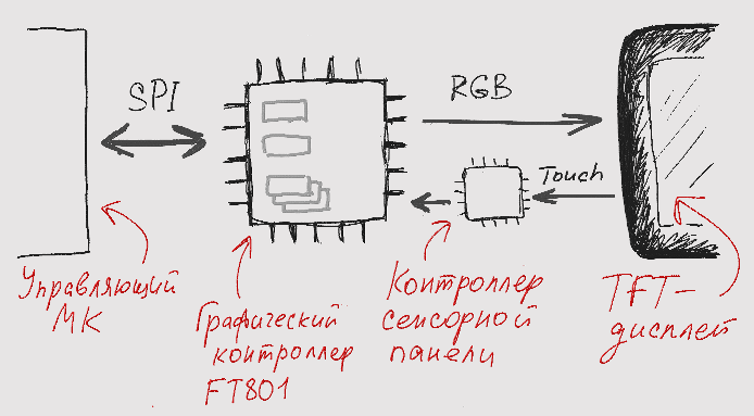
So, the Riverdi TFT module used consists of the actual display, the FT8xx series graphic controller from FTDI and additional components - the touch controller, the audio controller, etc. On the manufacturer’s website you can find a full list of available TFT modules, and on the EFO website you can find positions available from stock and current prices.
Displays differ in diagonal, resolution, brightness, type of backlight, the presence of a mounting or decorative frame, as well as the type of touch screen - capacitive TFT and resistive TFT are available, as well as displays without support for touch input. The on-board graphics controller matches the display capabilities: the FT800 controller is designed for resistive displays, the FT801 is for capacitive displays, and the older FT81x models feature support for relatively high resolution and other additional features.
I use the cutest module RVT43ULFNWC00 uxTouch series with a diagonal of 4.3 ", made in a black decorative frame. The module has a capacitive touch screen and, accordingly, an integrated graphics controller FT801.
We have already talked about the order of control of the Riverdi TFT module - the control controller is connected to the FT801 chip and exchanges simple commands with the graphics controller, that is, it reads and writes certain FT801 registers. In accordance with the commands received from the controlling controller, the graphic controller interacts with the display — it draws and displays images, realizes touch input and audio channel operation.
In capacitive TFT-modules, in contrast to models with a resistive screen, a separate touch panel controller is installed. However, the presence of this additional hardware block does not affect the TFT management process from the point of view of the programmer.
The FT801 graphics controller supports standard and advanced touch input modes. In the first case, only single touches can be detected, and in advanced mode multitouch is supported. The operating mode used is determined by the value in the register REG_CTOUCH_EXTENDED:
I will use only single-touch mode. Firstly, for my application, its capabilities are quite enough, and secondly, the program will be compatible with modules based on FT800.
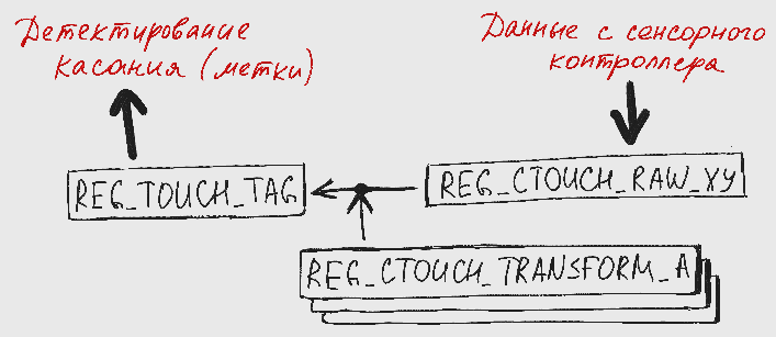
When you touch the TFT display, the touch panel controller transmits raw data about the touch area to the FT801. This data is written to the REG_CTOUCH_RAW_XY register of the graphics controller, after which the FT801 calculates the touch coordinates (x, y) and places the result in the REG_TOUCH_TAG_XY register. Coordinate calculation is a matrix transformation, in which data from REG_CTOUCH_RAW_XY and a coordinate matrix, which is stored in registers with REG_CTOUCH_TRANSFORM_A by REG_CTOUCH_TRANSFORM_F, participate. We still have to return to the registers REG_CTOUCH_TRANSFORM.
In principle, you can use data from REG_TOUCH_TAG_XY to detect a touch, but more convenient tools are provided for the programmer.
The simplest of these tools is tags (TAG). A label is a number from 1 to 255, which can be assigned to a graphic object, i.e. rectangle, point, line, button, text, and so on. While touching in the area of the marked graphic object, the value of the corresponding label will be set in the register REG_TOUCH_TAG. Thus, in order to detect a touch of an object, the host controller must periodically poll the REG_TOUCH_TAG register and compare the obtained value with the label assigned to the object of interest.
The FT801 controllers also support pushing tracking — automatically calculating the angle or linear distance between a touch point and a point with given coordinates. In this case, in addition to setting the label, you will need to set its tracking parameters (the Track () command), and to detect pressing, check the REG_TRACKER register instead of REG_TOUCH_TAG.
However, it's time to move on to examples.
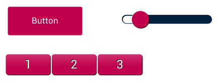
First, we consider widgets — graphic objects that are hardware implemented on a graphics controller. The three most simple widgets for the touch interface are the button, the row of buttons, and the slider.
To render widgets, use simple commands that are part of the FT800_2 library, which we discussed in the second article of the cycle . To draw the elements shown in the figure, these simple functions are:
In order for the elements not only to be displayed, but also to react to a touch, you need to add tags to the created objects and poll the register storing the label.
The elements of the object A series of buttons (Keys) tags are assigned automatically, therefore, to detect the pressing of buttons "1", "2" and "3" it is enough to simply poll the register REG_TOUCH_TAG:
Button type elements must be assigned manually:
When working with the slider, tracking is used - in addition to setting the label, you need to execute the Track command, which sets the tracking parameters, and you should poll the 32-bit register REG_TRACKER, and not the 8-bit REG_TOUCH_TAG:
The above code will allow you to register the position of the slider (in this case, it changes from 0 to 255) and redraw the slider in accordance with the current position of the slider.
In fact, it is not enough for the operation of the sensory elements to create a display list with a description of graphic elements and poll the corresponding register.
The fact is that after switching on and initializing the TFT module, all the registers of the graphics controller are reset to default values. Just above, we said that the matrix stored in REG_CTOUCH_TRANSFORM registers is used to calculate the pressure coordinates. So, these registers after initialization are also “empty”, and in order to write the correct values there, you need to calibrate the touch screen.
For calibration, use the instruction of the graphic coprocessor CMD_CALIBRATE. Roughly speaking, on the arrival of this instruction, the FT8xx graphics controller displays three points one after another on which you need to click. In accordance with the coordinates of the three contacts in the registers REG_CTOUCH_TRANSFORM enter the desired values.
The calibration function should be called up after the initialization of the TFT display. It all looks like this:
A project running on video can be viewed on developer.mbed.org .
Of course, it would be strange to force the user to calibrate the screen after each power up. Therefore, it makes sense to calibrate once, read the contents of registers REG_CTOUCH_TRANSFORM_A ... REG_CTOUCH_TRANSFORM_F, save the data, and then programmatically enter them into registers REG_CTOUCH_TRANSFORM after initializing the TFT module.
Calibration data can be stored in some EEPROM, and if conscience allows you to act completely clumsy, then you can “calibrate” something like this:
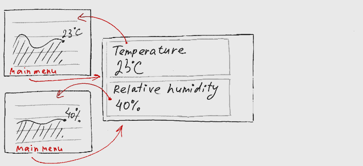
My final application is the main menu, which displays current data on temperature and relative humidity, as well as several subsections:

Since we will only deal with the issues of image rendering and Russification in the following article, today we will analyze the semi-finished product:
To navigate between the sections are two listings. The first is all the labels assigned to graphic objects:
The second is a list of screens between which we switch.
The logic of the application is described as follows:
To draw all three screens, only simple graphic primitives (LINES, POINTS, EDGE_STRIP_B and RECTS) and widgets for text and numbers are used. I suppose that after reading the article How to stop being afraid and fall in love with mbed [Part 2] and viewing the source code there shouldn't be any questions about drawing menu elements and graphs, so I’ll only focus on the implementation of touch input elements.
I do not use ready-made widgets from FTDI, since some buttons of the main menu will contain images and lines of different sizes, and also because the rounded corners of the buttons bother me . Therefore, my buttons are not button widgets, but rectangles on top of which text lines and other elements are displayed.
Labels (TAG) for "ordinary" graphic objects, such as rectangles, are set the same way as when using widgets. All graphic objects described after calling the TAG (CURR_HUM_PRESS) command are assigned the CURR_HUM_PRESS label. You can end the list of marked objects either by calling TAG () with a new argument, or by using the TAG_MASK (0) command, which prohibits label assignment. When using TAG_MASK (0), you need to remember to allow label assignment (TAG_MASK (1)) before the next call to TAG ().
Also it is necessary to provide some visualization of pressing. In my case, this is what is done:
a) If, after the previous frame is displayed on the TFT display, the button is fixed, on the new frame the button color changes from dark blue to blue (see code below),
b) After displaying the frame with the blue button, a delay of 150 milliseconds is performed (see the code above).
All buttons of the main menu are formed in the same way. By clicking on the Current temperature button, we go to the screen with a graph of temperature changes, by clicking on Current humidity - on the screen with a graph of changes in relative humidity.
From the screens with graphs, you can return to the main menu by clicking on the Back to main menu link. To create such a link, the same tools are used - the TAG (MENU_PRESS) tag, after which graphic objects are described - a text line and a line (underline).
It looks like this:
The source code for the project is available at developer.mbed.org .
Both this project and the demo project with pink widgets, and the programs reviewed in previous articles are successfully launched on the SLSTK3400A boards by Silicon Labs, ATSAMD21-XPRO by Atmel and WIZwiki-W7500P by Wiznet. You only need to change the names of the used GPIO and replace the target board before compiling. How can you not love mbed?
In conclusion, I traditionally thank the reader for his attention and remind you that questions about the use of products, about which we write on Habré, can also be asked by email, specified in my profile.
Content of the publication cycle:
- [Part 1] Overview of the used software and hardware solutions.
- [Part 2] Getting Started with the FT800 Graphics Controller. Use of ready mbed-libraries for peripheral devices.
- [Part 3] Connecting the sensor HYT-271. Create and publish in mbed your own library for peripherals.
- [Part 4] Application development: Program structure, working with a touch screen.
- [Part 5] Application development: Display images, Russification problems.
- [Part 6] Printing Body Parts
Following the results of the previous three articles, we received an mbed-project - a program that can be compiled into a working firmware for any debugging board with SPI and I2C interfaces and support in ARM mbed. The test subjects were debug boards from SLSTK3400A from Silicon Labs, ATSAMD21-XPRO from Atmel and WIZwiki-W7500P from Wiznet.
')
The implemented program performs two tasks so far - polling the temperature and relative humidity sensor HYT and outputting the measurement results to a Riverdi TFT-display. The project is available at developer.mbed.org .
Today we are starting to expand the base project - instead of a single working screen, a menu and several subsections will appear, between which you can switch using the touch interface.
1. The structure of the TFT module
So, the Riverdi TFT module used consists of the actual display, the FT8xx series graphic controller from FTDI and additional components - the touch controller, the audio controller, etc. On the manufacturer’s website you can find a full list of available TFT modules, and on the EFO website you can find positions available from stock and current prices.
Displays differ in diagonal, resolution, brightness, type of backlight, the presence of a mounting or decorative frame, as well as the type of touch screen - capacitive TFT and resistive TFT are available, as well as displays without support for touch input. The on-board graphics controller matches the display capabilities: the FT800 controller is designed for resistive displays, the FT801 is for capacitive displays, and the older FT81x models feature support for relatively high resolution and other additional features.
I use the cutest module RVT43ULFNWC00 uxTouch series with a diagonal of 4.3 ", made in a black decorative frame. The module has a capacitive touch screen and, accordingly, an integrated graphics controller FT801.
We have already talked about the order of control of the Riverdi TFT module - the control controller is connected to the FT801 chip and exchanges simple commands with the graphics controller, that is, it reads and writes certain FT801 registers. In accordance with the commands received from the controlling controller, the graphic controller interacts with the display — it draws and displays images, realizes touch input and audio channel operation.
In capacitive TFT-modules, in contrast to models with a resistive screen, a separate touch panel controller is installed. However, the presence of this additional hardware block does not affect the TFT management process from the point of view of the programmer.
2. Retrieving touch data
The FT801 graphics controller supports standard and advanced touch input modes. In the first case, only single touches can be detected, and in advanced mode multitouch is supported. The operating mode used is determined by the value in the register REG_CTOUCH_EXTENDED:
- 0: extended mode - extended mode,
- 1: FT800 compatibility mode - standard single-touch mode, is the default mode.
I will use only single-touch mode. Firstly, for my application, its capabilities are quite enough, and secondly, the program will be compatible with modules based on FT800.
When you touch the TFT display, the touch panel controller transmits raw data about the touch area to the FT801. This data is written to the REG_CTOUCH_RAW_XY register of the graphics controller, after which the FT801 calculates the touch coordinates (x, y) and places the result in the REG_TOUCH_TAG_XY register. Coordinate calculation is a matrix transformation, in which data from REG_CTOUCH_RAW_XY and a coordinate matrix, which is stored in registers with REG_CTOUCH_TRANSFORM_A by REG_CTOUCH_TRANSFORM_F, participate. We still have to return to the registers REG_CTOUCH_TRANSFORM.
In principle, you can use data from REG_TOUCH_TAG_XY to detect a touch, but more convenient tools are provided for the programmer.
The simplest of these tools is tags (TAG). A label is a number from 1 to 255, which can be assigned to a graphic object, i.e. rectangle, point, line, button, text, and so on. While touching in the area of the marked graphic object, the value of the corresponding label will be set in the register REG_TOUCH_TAG. Thus, in order to detect a touch of an object, the host controller must periodically poll the REG_TOUCH_TAG register and compare the obtained value with the label assigned to the object of interest.
The FT801 controllers also support pushing tracking — automatically calculating the angle or linear distance between a touch point and a point with given coordinates. In this case, in addition to setting the label, you will need to set its tracking parameters (the Track () command), and to detect pressing, check the REG_TRACKER register instead of REG_TOUCH_TAG.
However, it's time to move on to examples.
2.1. Work with ready-made widgets
First, we consider widgets — graphic objects that are hardware implemented on a graphics controller. The three most simple widgets for the touch interface are the button, the row of buttons, and the slider.
To render widgets, use simple commands that are part of the FT800_2 library, which we discussed in the second article of the cycle . To draw the elements shown in the figure, these simple functions are:
TFT.FgColor(0xC1004D); TFT.Keys(27, 127, 271, 41, 29, 0, "123"); TFT.Button(26, 33, 120, 36, 27, OPT_FLAT, "Button"); TFT.Slider(244, 45, 161, 17, 0, 17, 100); In order for the elements not only to be displayed, but also to react to a touch, you need to add tags to the created objects and poll the register storing the label.
The elements of the object A series of buttons (Keys) tags are assigned automatically, therefore, to detect the pressing of buttons "1", "2" and "3" it is enough to simply poll the register REG_TOUCH_TAG:
TFT.Keys(27, 127, 271, 41, 29, 0, "123"); char pressedButton = TFT.Rd8(REG_TOUCH_TAG); Button type elements must be assigned manually:
TFT.DL(TAG(1)); TFT.Button(26, 33, 120, 36, 27, OPT_FLAT, "Button"); char pressedButton = TFT.Rd8(REG_TOUCH_TAG); When working with the slider, tracking is used - in addition to setting the label, you need to execute the Track command, which sets the tracking parameters, and you should poll the 32-bit register REG_TRACKER, and not the 8-bit REG_TOUCH_TAG:
char sliderVal = 0; TFT.Track(244, 45, 161, 17, 2); ... while(1) { TFT.DL(TAG(2)); TFT.Slider(244, 45, 161, 17, 0, sliderVal, 255); int pressedSlider = TFT.Rd32(REG_TRACKER); sliderVal = (pressedSlider >> 16) * 255 / 65536; } The above code will allow you to register the position of the slider (in this case, it changes from 0 to 255) and redraw the slider in accordance with the current position of the slider.
2.2. Screen calibration
In fact, it is not enough for the operation of the sensory elements to create a display list with a description of graphic elements and poll the corresponding register.
The fact is that after switching on and initializing the TFT module, all the registers of the graphics controller are reset to default values. Just above, we said that the matrix stored in REG_CTOUCH_TRANSFORM registers is used to calculate the pressure coordinates. So, these registers after initialization are also “empty”, and in order to write the correct values there, you need to calibrate the touch screen.
For calibration, use the instruction of the graphic coprocessor CMD_CALIBRATE. Roughly speaking, on the arrival of this instruction, the FT8xx graphics controller displays three points one after another on which you need to click. In accordance with the coordinates of the three contacts in the registers REG_CTOUCH_TRANSFORM enter the desired values.
The library FT800_2 provides a standard function for calibration
DLstart(); DL(CLEAR_COLOR_RGB(64,64,64)); DL(CLEAR(1,1,1)); DL(COLOR_RGB(0xff,0xff,0xff)); Text((DispWidth/2), (DispHeight/2), 27, OPT_CENTER, "Please Tap on the dot"); Calibrate(0); Flush_Co_Buffer(); WaitCmdfifo_empty(); The calibration function should be called up after the initialization of the TFT display. It all looks like this:
A project running on video can be viewed on developer.mbed.org .
Of course, it would be strange to force the user to calibrate the screen after each power up. Therefore, it makes sense to calibrate once, read the contents of registers REG_CTOUCH_TRANSFORM_A ... REG_CTOUCH_TRANSFORM_F, save the data, and then programmatically enter them into registers REG_CTOUCH_TRANSFORM after initializing the TFT module.
Calibration data can be stored in some EEPROM, and if conscience allows you to act completely clumsy, then you can “calibrate” something like this:
void Display::Calibration() { char calibration[25] = {98, 99, 0, 0, 182, 254, 255, 255, 245, 142, 248, 255, 117, 254, 255, 255, 34, 98, 0, 0, 123, 154, 248, 255}; for (int i = 0; i < 24; i++) { (*_TFT).Wr8(REG_TOUCH_TRANSFORM_A + i, calibration[i]); } } 3. Using the touch interface in your own project
My final application is the main menu, which displays current data on temperature and relative humidity, as well as several subsections:
Since we will only deal with the issues of image rendering and Russification in the following article, today we will analyze the semi-finished product:
To navigate between the sections are two listings. The first is all the labels assigned to graphic objects:
typedef enum { NONE_PRESS, CURR_TEMP_PRESS, CURR_HUM_PRESS, MENU_PRESS, } pressValues; The second is a list of screens between which we switch.
typedef enum { MENU_SCREEN, CURR_HUM_SCREEN, CURR_TEMP_SCREEN, } screenValues; The logic of the application is described as follows:
disp.activeScreen = MENU_SCREEN; disp.pressedButton = NONE_PRESS; // change active screen depending on pressed area while(1) { dataUpdate(); disp.pressedButton = disp.GetTouch(); // Main menu screen if (disp.activeScreen == MENU_SCREEN) { disp.MainMenu(SENSOR.humidity, SENSOR.temperature); if (disp.pressedButton) { wait_ms(150); if (disp.pressedButton == CURR_TEMP_PRESS) { disp.activeScreen = CURR_TEMP_SCREEN; } else if (disp.pressedButton == CURR_HUM_PRESS) { disp.activeScreen = CURR_HUM_SCREEN; } disp.pressedButton = NONE_PRESS; } // Any other screen } else { // You can back to main menu from any screen if (disp.pressedButton == MENU_PRESS) { disp.pressedButton = NONE_PRESS; disp.activeScreen = MENU_SCREEN; } else { // Screen with current temperature / humidity if (disp.activeScreen == CURR_TEMP_SCREEN) { disp.CurrentTemperature(SENSOR.temperature); } else if (disp.activeScreen == CURR_HUM_SCREEN) { disp.CurrentHumidity(SENSOR.humidity); } } } } To draw all three screens, only simple graphic primitives (LINES, POINTS, EDGE_STRIP_B and RECTS) and widgets for text and numbers are used. I suppose that after reading the article How to stop being afraid and fall in love with mbed [Part 2] and viewing the source code there shouldn't be any questions about drawing menu elements and graphs, so I’ll only focus on the implementation of touch input elements.
I do not use ready-made widgets from FTDI, since some buttons of the main menu will contain images and lines of different sizes
Labels (TAG) for "ordinary" graphic objects, such as rectangles, are set the same way as when using widgets. All graphic objects described after calling the TAG (CURR_HUM_PRESS) command are assigned the CURR_HUM_PRESS label. You can end the list of marked objects either by calling TAG () with a new argument, or by using the TAG_MASK (0) command, which prohibits label assignment. When using TAG_MASK (0), you need to remember to allow label assignment (TAG_MASK (1)) before the next call to TAG ().
Also it is necessary to provide some visualization of pressing. In my case, this is what is done:
a) If, after the previous frame is displayed on the TFT display, the button is fixed, on the new frame the button color changes from dark blue to blue (see code below),
b) After displaying the frame with the blue button, a delay of 150 milliseconds is performed (see the code above).
void Display::MainMenu(float humidity, float temperature) { ... (*_TFT).DL(TAG_MASK(1)); (*_TFT).DL(TAG(CURR_HUM_PRESS)); (*_TFT).DL(COLOR_RGB(9, 0, 63)); // , if (pressedButton == CURR_HUM_PRESS) { (*_TFT).DL(COLOR_RGB(75, 70, 108)); } (*_TFT).DL(BEGIN(RECTS)); (*_TFT).DL(VERTEX2II(12, 62, 0, 0)); (*_TFT).DL(VERTEX2II(12 + 400, 62 + 93, 0, 0)); (*_TFT).DL(COLOR_RGB(255, 255, 255)); (*_TFT).Text(12 + 10, 62 + 5, 30, 0, "Current humidity (rH)"); // (32 -> "32%") CreateStringTempHum(humidityStr, humidity, 0); (*_TFT).Text(12 + 10, 62 + 45, 31, 0, humidityStr); (*_TFT).DL(TAG_MASK(0)); ... } All buttons of the main menu are formed in the same way. By clicking on the Current temperature button, we go to the screen with a graph of temperature changes, by clicking on Current humidity - on the screen with a graph of changes in relative humidity.
From the screens with graphs, you can return to the main menu by clicking on the Back to main menu link. To create such a link, the same tools are used - the TAG (MENU_PRESS) tag, after which graphic objects are described - a text line and a line (underline).
(*_TFT).DL(TAG_MASK(1)); (*_TFT).DL(TAG(MENU_PRESS)); (*_TFT).DL(COLOR_RGB(0, 0, 0)); (*_TFT).Text(14, 240, 22, 0, "Back to main menu"); (*_TFT).DL(BEGIN(LINES)); (*_TFT).DL(LINE_WIDTH(8)); (*_TFT).DL(VERTEX2F(15 * 16, 260 * 16)); (*_TFT).DL(VERTEX2F(155 * 16, 260 * 16)); (*_TFT).DL(TAG_MASK(0)); It looks like this:
The source code for the project is available at developer.mbed.org .
Both this project and the demo project with pink widgets, and the programs reviewed in previous articles are successfully launched on the SLSTK3400A boards by Silicon Labs, ATSAMD21-XPRO by Atmel and WIZwiki-W7500P by Wiznet. You only need to change the names of the used GPIO and replace the target board before compiling. How can you not love mbed?
Conclusion
In conclusion, I traditionally thank the reader for his attention and remind you that questions about the use of products, about which we write on Habré, can also be asked by email, specified in my profile.
Source: https://habr.com/ru/post/310720/
All Articles