Launch Linux on FPGA: Hello, World
UPD 09/21/16: BusyBox is now successfully launched.
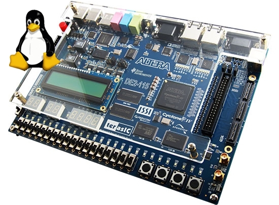
Inspired by a series of articles on the Mars Rover project site, in which the author tries to launch an open system on the Amber SoC chip and Linux on the FPGA-based Mars Rover 2, I decided to try to repeat this experience on my Terasic DE2-115 board . But, instead of theold as shit mammoth obsolete version of Linux 2.4.27, I will be running the latest version of Linux at the moment - 4.8.0-rc5.
The Amber processor core is a 32-bit RISC processor, fully compatible with the architecture and the ARM v2a command system, which allows compiling programs for it using GCC. In addition to the processor itself, the Amber project provides several peripheral devices as part of a system on a chip, including a UART, a timer, and an Ethernet MAC. The processor core is available in two versions:
As you can see, the performance of the processor core is comparable to the performance of cores based on later versions of the ARM architecture, such as ARMv4 and ARMv5. The ARMv2a architecture is implemented in the Amber processor for the reason that it is not covered by patents and its implementations can be freely distributed. However, some problems are connected with this - this architecture is considered obsolete in GCC, from where its support is gradually being “cut out”, and support for this architecture has been removed from the Linux kernel a long time ago.
An important feature of the architecture is that, unlike the newer versions of the ARM architecture, the processor does not support the THUMB mode, it lacks the CPSR / SPSR registers and support for MSR / MRS instructions, and the processor flags are contained in the PC register bits:
')

Because of this, the processor can address a maximum of 64 MB of memory (26 bits) in the PC register, the two youngest of which are always 0, because The instructions are always aligned with the word boundary, so the two lower bits of the register are used as flags defining the processor operation mode (user / privileged, interrupt handler). In other registers, the processor can address up to 4 GB of memory. More details about the architecture of the processor core and the set of commands implemented in it can be found here and here .
Unfortunately, the Sourcery CodeBench Lite compiler, which was used by the author of articles about porting a project to the Mars Rover board, is no longer available for download, but this is not a very big problem. To install the compiler, you can use crosstool-NG or
To install using crosstool-NG, it suffices to use the out
This compiler will be used to build the Linux kernel and bare-metal programs, such as the initial boot loader, and a simple application that prints Hello, World to the serial port.
Download the project distribution kit with GitHub and look inside: the project is divided into 2 parts - the
Go to the folder
As a result, among other things, the file
The author of the original articles that I used was used to simulate the Icarus Verilog project - a free and very popular simulator, but the problem is that it works terribly slowly - on my machine with a 2.6 GHz processor, the clock frequency of the Amber core during simulation in Icarus Verilog is about 16 kHz, and each character in the string “Hello, World” from the example above is displayed for about half a second. This speed is sufficient if you need to debug the execution of a small program, such as a bootloader or the same hello-world, but is unacceptable, if you want to debug the boot of the entire Linux kernel - you have to wait for ages.
Therefore, we will use the Verilator simulator, which compiles Verilog in C ++ and works very fast - Hello World prints instantly without any visible delay, and the clock frequency on my machine is about 1.5 MHz, which is 100 times faster than Icarus Verilog! By the way, the debugging process of launching the Linux kernel took me about a week, and the simulation helped a lot, because in the simulation mode, the test bench code writes to the text log file an assembler listing of all the instructions executed by the processor, including jumps to addresses, asynchronous and software interrupts, etc. A sort of disassembler implemented in Verilog.
We install Verilator according to the instructions from the official site , go to the
Next, execute the following commands:
As a result, the simulation will be launched and we will see the long-awaited Hello, World:
This means that the processor successfully read and executed our program compiled by GCC under ARM!
If you wish, you can add the

Before building the Linux kernel, create an environment for compiling custom programs for our system (based on uClibc-ng) and generate a file that will be added to the kernel as an initramfs during the build process. To do this, use Buildroot, which can be downloaded from here .
As a result, we will have an armchildbut it still doesn’t start up completely (now it is running), but in this article we’ll restrict ourselves to a simple “Hello, World” as the process
After successful execution of these commands,
Unlike the example that we launched in the Verilator simulator, this new “Hello, World” is not working as a bare-metal application, but as a user application for Linux — the text will be output to the serial port using the uClibc standard library
Naturally, in order to launch the freshest core, it had to make some changes. For the most part, these changes are related to the interrupt handling code and processor mode switching code, since this code is architecture dependent. Next, I adapted the code to support the Integrator platform (mach-integrator), since In the original patch of the author of the Amber project for the 2.4 kernel, there are hints that this platform is the prototype of the Amber SoC architecture (in particular, it was discovered that peripheral devices, such as an interrupt controller, a timer, and a serial port, are implemented compatible with the device drivers used on this platform) and created on its basis a new platform Amber.
Fortunately, the debugging clock is over, and now the assembly of the working core is done with a flick of the wrist. Those who wish to repeat it can clone the source and execute the following commands:
After the kernel is assembled, the
To build the bootloader, go to the
For those who have a Terasic DE2-115 board, it’s time to open the
After downloading the bitstream in the terminal configured at 921600 baud, the prompt Amber will appear immediately. Next, you need to type the
Finally, when both files are loaded into random access memory (SDRAM), you can enter the
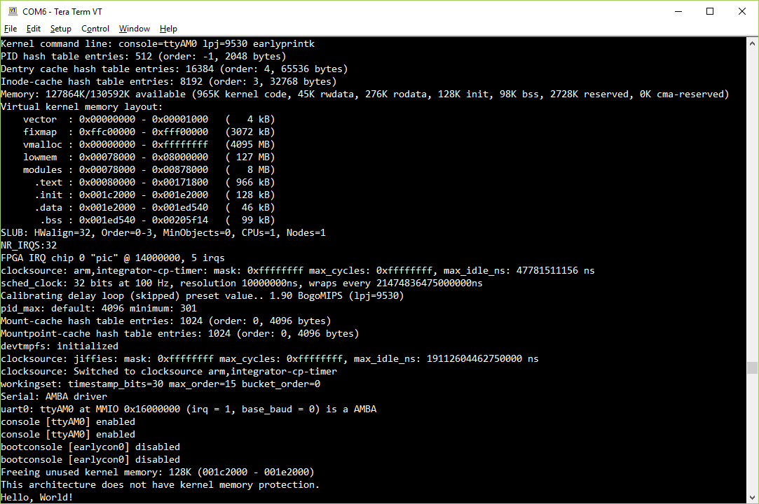
Our "Hello, World" was launched as the first user process (
If you do not have a Terasic DE2-115 board or any other board with a FPGA of sufficient size, you can still run Linux in the Verilator simulator. To do this, add the
In addition, you will need to slightly correct the bootloader code for the simulation, commenting out the
Of course, Linux, which eventually started, is not quite similar to the one we used to see on servers and workstations, due to the fact that the Amber processor core does not have a MMU (Memory Management Unit) and, as a result, virtual memory support (all memory is physical), memory protection (any application can corrupt kernel memory or communicate with devices bypassing it, via the Wishbone bus), copy-on-write, etc. NOMMU Linux currently does not support ELF executable files (although There are developments on the support of the format FDPIC ELF) and dynamic bib ioteki - used instead bFLT format (Binary Flat) - a simple format based on
The practical benefits of the work done are still there, even such “trimmed” versions of Linux work in many devices based on microcontrollers with limited resources. I hope that the habrayusers who are keen on FPGA programming can learn something useful by experimenting with full-fledged Linux on an FPGA-synthesized processor (which, incidentally, only takes up 8% of capacity on DE2-115 or about 10,000 LE). If you have another board based on Altera or Xilinx, then porting to it is not difficult, because Most of the work has already been done. Of course, there are already more practical solutions that are more interesting from a practical point of view, such as Xilinx Zynq, Altera Cyclone V SoC, which contain a full-fledged ARM-SoC on a single chip with FPGA, but the solution presented in this article allows Linux to run even for owners of simple boards with no very powerful FPGAs on board. The remaining free logic can be used to implement new custom peripherals, which can be “hung” on the Wishbone bus and made available from the OS using drivers.
The Terasic DE2-115 board is truly one of the most powerful debugging boards, on the basis of which interesting projects have already been made (this is the clearest example and another one ). She has on board a wide range of peripherals:
Of all this wealth, I have used only RAM in this project. In the future, if there is time, I want to compile U-Boot and place it in the built-in flash memory, in the bootloader code in the FPGA, load U-Boot, which would then load the Linux kernel and root file system from the SD memory card. In addition, I would like to try to implement the support of peripheral devices available on the card - Ethernet, for example.
Inspired by a series of articles on the Mars Rover project site, in which the author tries to launch an open system on the Amber SoC chip and Linux on the FPGA-based Mars Rover 2, I decided to try to repeat this experience on my Terasic DE2-115 board . But, instead of the
Amber Crystal System
The Amber processor core is a 32-bit RISC processor, fully compatible with the architecture and the ARM v2a command system, which allows compiling programs for it using GCC. In addition to the processor itself, the Amber project provides several peripheral devices as part of a system on a chip, including a UART, a timer, and an Ethernet MAC. The processor core is available in two versions:
| Amber 23 | Amber 25 | |
| Conveyor | three level | five level |
| Cache | common (code + data) | separated |
| Wishbone bus width | 32 bits | 128 bits |
| Performance | 0.75 DMIPS / MHz | 1.05 DMIPS / MHz |
As you can see, the performance of the processor core is comparable to the performance of cores based on later versions of the ARM architecture, such as ARMv4 and ARMv5. The ARMv2a architecture is implemented in the Amber processor for the reason that it is not covered by patents and its implementations can be freely distributed. However, some problems are connected with this - this architecture is considered obsolete in GCC, from where its support is gradually being “cut out”, and support for this architecture has been removed from the Linux kernel a long time ago.
An important feature of the architecture is that, unlike the newer versions of the ARM architecture, the processor does not support the THUMB mode, it lacks the CPSR / SPSR registers and support for MSR / MRS instructions, and the processor flags are contained in the PC register bits:
')
Because of this, the processor can address a maximum of 64 MB of memory (26 bits) in the PC register, the two youngest of which are always 0, because The instructions are always aligned with the word boundary, so the two lower bits of the register are used as flags defining the processor operation mode (user / privileged, interrupt handler). In other registers, the processor can address up to 4 GB of memory. More details about the architecture of the processor core and the set of commands implemented in it can be found here and here .
Installing ARM Cross Compiler
Unfortunately, the Sourcery CodeBench Lite compiler, which was used by the author of articles about porting a project to the Mars Rover board, is no longer available for download, but this is not a very big problem. To install the compiler, you can use crosstool-NG or
crossdev in Gentoo Linux.To install using crosstool-NG, it suffices to use the out
arm-unknown-eabi configuration: $ ct-ng arm-unknown-eabi $ ct-ng build This compiler will be used to build the Linux kernel and bare-metal programs, such as the initial boot loader, and a simple application that prints Hello, World to the serial port.
Compile Hello World and run in the Verilog simulator Verilator
Download the project distribution kit with GitHub and look inside: the project is divided into 2 parts - the
hw folder contains the source of the “hardware” part in the Verilog language, and the sw folder contains the source code of the programs that will be run on the processor, and some auxiliary utilities used in assembling and transforming ELF and BIN file formats into a format supported by Xilinx tools and Amber test bench scripts.Go to the folder
sw/hello and compile the program hello-world.c : $ cd sw/hello-world $ export AMBER_CROSSTOOL=arm-unknown-eabi $ make As a result, among other things, the file
hello-world.mem will be generated - a text file with the contents of the compiled program, suitable for downloading to the simulator and to the Boot ROM of our processor.The author of the original articles that I used was used to simulate the Icarus Verilog project - a free and very popular simulator, but the problem is that it works terribly slowly - on my machine with a 2.6 GHz processor, the clock frequency of the Amber core during simulation in Icarus Verilog is about 16 kHz, and each character in the string “Hello, World” from the example above is displayed for about half a second. This speed is sufficient if you need to debug the execution of a small program, such as a bootloader or the same hello-world, but is unacceptable, if you want to debug the boot of the entire Linux kernel - you have to wait for ages.
Therefore, we will use the Verilator simulator, which compiles Verilog in C ++ and works very fast - Hello World prints instantly without any visible delay, and the clock frequency on my machine is about 1.5 MHz, which is 100 times faster than Icarus Verilog! By the way, the debugging process of launching the Linux kernel took me about a week, and the simulation helped a lot, because in the simulation mode, the test bench code writes to the text log file an assembler listing of all the instructions executed by the processor, including jumps to addresses, asynchronous and software interrupts, etc. A sort of disassembler implemented in Verilog.
We install Verilator according to the instructions from the official site , go to the
hw/de2_115/tb folder, where the modified testbench is located, and make . obj_dir Verilog compiler warnings stream, the result will be the obj_dir folder, and in it the Vtb executable file, which we will run to simulate the operation of the system.Next, execute the following commands:
$ cp ../../../sw/hello-world/hello-world.mem ./boot-loader.mem $ ./obj_dir/Vtb As a result, the simulation will be launched and we will see the long-awaited Hello, World:
Load boot memory from boot-loader.mem Read in 961 lines Hello, World! This means that the processor successfully read and executed our program compiled by GCC under ARM!
If you wish, you can add the
verilator key to the list of startup keys of the verilator the --trace , then another test file will be generated - out.vcd , which can then be opened by the GTKWave program, and see the waveforms of various signals inside the processor and other blocks :Build initramfs with Builtroot
Before building the Linux kernel, create an environment for compiling custom programs for our system (based on uClibc-ng) and generate a file that will be added to the kernel as an initramfs during the build process. To do this, use Buildroot, which can be downloaded from here .
$ make amber_defconfig $ make As a result, we will have an armchild
arm-buildroot-uclinux-uclibcgnueabi and an image of the file system in ./output/images/rootfs.cpio . The path to this image will need to be specified in the kernel configuration file, the parameter CONFIG_INITRAMFS_SOURCE . BusyBox is included in the file system image, /sbin/init . To do this, in the directory where BuildRoot was going to create a file hello.c with the content known to each programmer, and run the following commands: $ ./output/host/usr/bin/arm-buildroot-uclinux-uclibcgnueabi-gcc -o hello hello.c $ mv hello output/target/sbin/init $ rm hello.gdb $ make After successful execution of these commands,
./output/images/rootfs.cpio will be rebuilt with our application instead of BusyBox. This way of replacing files is suitable to quickly check something, for the full addition and replacement of files in rootfs during the build process there is a configuration option BR2_ROOTFS_OVERLAY .Unlike the example that we launched in the Verilator simulator, this new “Hello, World” is not working as a bare-metal application, but as a user application for Linux — the text will be output to the serial port using the uClibc standard library
write system call and transfer control to the kernel through a software interrupt, the kernel will transfer control to the tty driver, then the serial port driver, and finally the message will be output.Build the Linux kernel and boot loader
Naturally, in order to launch the freshest core, it had to make some changes. For the most part, these changes are related to the interrupt handling code and processor mode switching code, since this code is architecture dependent. Next, I adapted the code to support the Integrator platform (mach-integrator), since In the original patch of the author of the Amber project for the 2.4 kernel, there are hints that this platform is the prototype of the Amber SoC architecture (in particular, it was discovered that peripheral devices, such as an interrupt controller, a timer, and a serial port, are implemented compatible with the device drivers used on this platform) and created on its basis a new platform Amber.
Fortunately, the debugging clock is over, and now the assembly of the working core is done with a flick of the wrist. Those who wish to repeat it can clone the source and execute the following commands:
$ make ARCH=arm CROSS_BUILD=arm-none-eabi- amber_defconfig $ make -j8 ARCH=arm CROSS_BUILD=arm-none-eabi- Image $ make ARCH=arm CROSS_BUILD=arm-none-eabi- arch/arm/boot/dts/amber-de2115.dts After the kernel is assembled, the
arch/arm/boot/Image and arch/arm/boot/dts/amber-de2115.dtb files will be created, ready to be loaded into the board using a bootloader via the serial port using the XMODEM protocol.To build the bootloader, go to the
sw/boot-loader-serial folder, do make (don't forget about the environment variable AMBER_CROSSTOOL ) and get the file boot-loader-serial.mem , which can be converted to MIF, which accepts Altera, using the utility mem2mif Quartus II as a memory initialization file.Putting it all together
For those who have a Terasic DE2-115 board, it’s time to open the
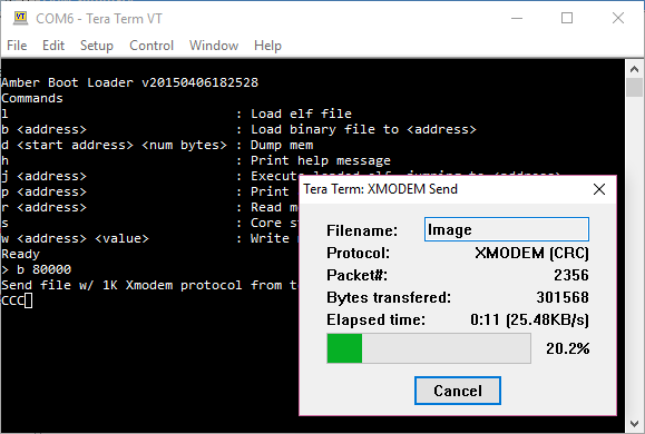
de2_115.qpf project and synthesize it (note that I have a serial port on the EXT_IO connector instead of the RS232 board, since there are no COM ports on my motherboard ), specify the de2_115_sram_2048_32_byte_en memory received in the previous step as boot-loader-serial.mif as the file for initialization and load the bitstream into the board. Since the Amber processor, for one developer, did not implement the reset logic for the known reasons, it is possible to reset the processor to the initial state only by reloading the bitstream. At the same time, if in the process you hold down the KEY0 button, the processor will not start the program until it is released. I used this button to debug Verilog code using SignalTap. But if you let it go, then just reloading the bitstream will help start all over again.After downloading the bitstream in the terminal configured at 921600 baud, the prompt Amber will appear immediately. Next, you need to type the
b 80000 command and send the Linux kernel file ( arch/arm/boot/Image ) generated earlier with XMODEM, and then again type the b 78000 command and send the DTB file, which describes which devices to search for which addresses, what drivers for them to load, how much RAM is in the system, a command line with kernel parameters and other information. I patched the bootloader in such a way that it sends the address 0x78000 to the kernel as the address where to look for DTB, so we load it at this address.Finally, when both files are loaded into random access memory (SDRAM), you can enter the
j 80000 command in the boot loader console. The Linux download starts, and if everything is done correctly, the result will be something like this:Our "Hello, World" was launched as the first user process (
/sbin/init ) and brought the cherished phrase to the screen through the standard library and the kernel. Wow, isn't it?If you do not have a Terasic DE2-115 board or any other board with a FPGA of sufficient size, you can still run Linux in the Verilator simulator. To do this, add the
-DAMBER_LOAD_MAIN_MEM=1 and -DAMBER_LOAD_DTB_MEM=1 keys to hw/de2_115/tb/Makefile and rebuild the Vtb executable file. Then, using the amber-bin2mem we create the kernel and DTB files for the simulator: $ amber-bin2mem arch/arm/boot/Image 80000 > vmlinux.mem $ amber-bin2mem arch/arm/boot/dts/amber-de2115.dtb 78000 > dtb.mem In addition, you will need to slightly correct the bootloader code for the simulation, commenting out the
main function call as in the normal mode it requests commands from the user. Then the loader will immediately transfer control to the Linux kernel. Copy the *.mem files to the *.mem folder, run: ./obj_dir/Vtb and watch Linux boot.Limitations, practical benefits
Of course, Linux, which eventually started, is not quite similar to the one we used to see on servers and workstations, due to the fact that the Amber processor core does not have a MMU (Memory Management Unit) and, as a result, virtual memory support (all memory is physical), memory protection (any application can corrupt kernel memory or communicate with devices bypassing it, via the Wishbone bus), copy-on-write, etc. NOMMU Linux currently does not support ELF executable files (although There are developments on the support of the format FDPIC ELF) and dynamic bib ioteki - used instead bFLT format (Binary Flat) - a simple format based on
a.out . And if you run, say, N instances of an application on such a system, then exactly as many copies of it will be in memory.The practical benefits of the work done are still there, even such “trimmed” versions of Linux work in many devices based on microcontrollers with limited resources. I hope that the habrayusers who are keen on FPGA programming can learn something useful by experimenting with full-fledged Linux on an FPGA-synthesized processor (which, incidentally, only takes up 8% of capacity on DE2-115 or about 10,000 LE). If you have another board based on Altera or Xilinx, then porting to it is not difficult, because Most of the work has already been done. Of course, there are already more practical solutions that are more interesting from a practical point of view, such as Xilinx Zynq, Altera Cyclone V SoC, which contain a full-fledged ARM-SoC on a single chip with FPGA, but the solution presented in this article allows Linux to run even for owners of simple boards with no very powerful FPGAs on board. The remaining free logic can be used to implement new custom peripherals, which can be “hung” on the Wishbone bus and made available from the OS using drivers.
Plans
The Terasic DE2-115 board is truly one of the most powerful debugging boards, on the basis of which interesting projects have already been made (this is the clearest example and another one ). She has on board a wide range of peripherals:
- 128 MB SDRAM
- 8 MB SPI Flash
- LEDs and seven-segment indicators
- 16x2 liquid crystal display
- 24-bit audio codec
- SD card slot
- 2 gigabit ethernet ports
- VGA monitor output, PS / 2 keyboard
- USB ports
Of all this wealth, I have used only RAM in this project. In the future, if there is time, I want to compile U-Boot and place it in the built-in flash memory, in the bootloader code in the FPGA, load U-Boot, which would then load the Linux kernel and root file system from the SD memory card. In addition, I would like to try to implement the support of peripheral devices available on the card - Ethernet, for example.
Source: https://habr.com/ru/post/310056/
All Articles