How to stop being afraid and fall in love with mbed [Part 2]
We continue a series of publications devoted to the use of the ARM mbed environment for creating a prototype measuring device.
Let me remind you that we are talking about the development of a device with a touch screen, which serves for high-speed measurement of temperature and relative humidity. The most interesting thing about this story is the approach to creating firmware. The program is written using the online IDE mbed, which allows you to create iron-independent code that works equally well on debug boards from SiLabs, Atmel, Wiznet, STM32, NXP and other manufacturers.
Today we are starting to work with displaying a picture on a TFT display.
')
Content of the publication cycle:
The second part is under the cut.
In the last article , we gave a brief overview of the used hardware modules, including the TFT touchscreen display - a module from Riverdi, which consists of a display and an FTD00 integrated graphics controller from FTDI. Today we will look at the general issues of working with such a module and “make friends” with a debugging board.
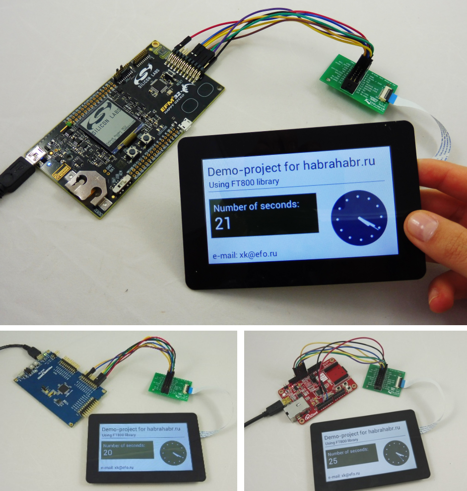
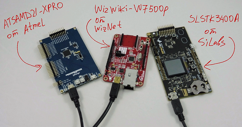
Since for writing software is used exclusively online IDE mbed, the resulting program should run without problems on the debugging boards SLSTK3400A from SiLabs, ATSAMD21-XPRO from Atmel and WIZwiki-W7500P from Wiznet.
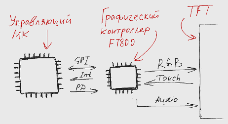
So, all the procedures related to graphics output, touch input and audio channel operation are hardware implemented on the FT800 series graphic controller. The task of the developer is to control the FTDI chip from the main microcontroller - roughly speaking, reading and writing certain registers of the FT800 controller via the SPI or I2C * interface.
* we will further assume that the host controller is connected to the FT800 via the SPI interface. Most often it is.
Three types of commands are used to control the graphics controller:
All functions for interacting with a TFT display consist of receiving and transmitting such commands. FTDI provides a library that implements all operations supported by the graphics controller. These are several dozens of functions of varying complexity, which, nevertheless, always consist of their basic functions — receiving and transmitting via the SPI instructions the Host command, Host Memory Read, and Host Memory Write.
In general, to begin working with the display, it is necessary to adapt the functions of the FTDI library that address the peripheral devices of the master controller to the host controller being used. This is the setting of the SPI interface, as well as the functions of reading and writing SPI data of a given format. After the iron-dependent functions are changed in accordance with the features of the host controller, you can begin to use all the features of the FTDI libraries and examples.
You can find out where to download the library and examples for the FT800 modules, how to adapt the library for the target host microcontroller and how to use the available functions for practical tasks from materials from the manufacturer and from the articles of my colleague Sergey Dolgushin:
In the case of program development in mbed, the task is simplified even more - since the code written in mbed itself is iron-independent, even the basic functions of the FTDI library become universal. Thus, to control the display from debug boards from different manufacturers, you can use the same mbed library without making any changes.
To connect a TFT module, eight signals are required:
The intr and pd signals can be implemented on any free digital lines of the host controller.
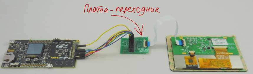
For most Riverdi TFT modules, the module is connected to a control controller via a flat cable. To connect the cable to the debug boards, a break-out adapter board 20 is proposed. When using it, you need to pay attention to the fact that in addition to the VDD power line, the board is powered separately for the display backlight - the signal BLVDD. To work with the display, power must be supplied to both VDD and BLVDD, so it makes sense to immediately combine the lines and supply power only to VDD.
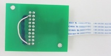
With GND and BLGND, this trick is not required.
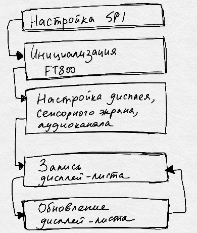 The initialization procedure consists of three steps: setting up the SPI interface, initializing the FT800 graphics controller, and initializing the TFT display.
The SPI interface of the host processor is always master and operates in “mode 0” mode with the high bit transmitted first (MSB first). The maximum operating frequency of the interface is 30 MHz, however, before the end of the initialization procedure, the frequency should not be set above 11 MHz.
The initialization of the graphic controller consists in the sequential execution of the following operations.
First, the PD signal translates to 20 ms at a low level, and then another 20 ms at a high level. Thus, the graphics controller goes into standby mode. After that, several commands of the Host command group are sent to the FTDI controller: the ACTIVE (0x00) command switches the controller to active mode, the CORERST command (0x68) resets all registers and logic circuits, then the CLKEXT command (0x44) selects clocking from an external source, and after This selects the operating frequency of the controller - 48 or 36 MHz using the CLK48M (0x62) or CLK36M (0x61) command, respectively.
Of course, other scenarios for setting up the FT800 controller are possible, but most often the procedure looks like this.
If the initialization of the graphic controller was successful, then in the REG_ID register of the graphic controller is set to 0x7C. After verifying this reference value, you can increase the SPI speed.
The last preparatory step is to configure the parameters of the TFT-display. The essence of the procedure is to write to the specific registers of the graphic controller of the parameters of a specific TFT display. We once explain the graphics controller to which particular display it is connected, and then use the universal library functions.
After setting, a blank screen is displayed. Further, if necessary, the configuration of the touch input and the audio channel is carried out. All these procedures are repeatedly described by the manufacturer, therefore, probably, they do not need explanations.
After initialization, working with the display is reduced to forming the next display list and loading it onto the graphics controller. The display list is a list of commands that, as a result of execution of which, the FTDI controller displays a kind of image.
The display list begins with writing the command CMD_DLSTART to the graphics controller and ends with writing the command DISPLAY (). The display of the display list occurs by writing the standard value to the register REG_DLSWAP.
The body of the display list can contain up to 2048 instructions. All of them are simple commands like setting the color of objects and drawing graphic primitives - lines, rectangles, points, etc.
The FTDI graphics controller consists of several nodes, including the main processor, an additional graphics co-processor, audio processor, etc. The main processor of the FT800 is responsible for the execution of simple commands of the display list, but the FTDI chips allow working with more complex objects - widgets. Widgets are buttons, sliders, scales, gradients, text strings, numbers, and so on. Despite the fact that widgets are rendered by the coprocessor, simple basic functions and functions of widgets drawing can be interleaved while forming the display list.
In the last article , a draft of the project was prepared - a short program that displays a seconds counter on a virtual COM port. Today, we will connect the FT800 library to the project and will display the seconds counter on the TFT display.
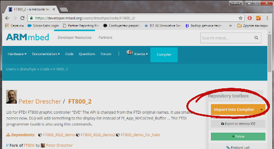
Among the mbed-developers, there is already a person who dealt with the FT800 graphics controller. This same person, Peter Drescher, successfully adapted the FTDI library for mbed, provided it with an example of use and photographs. Thanks, Peter!
To use the library in your project, click on the Import library on the dedicated FT800 page , get into your compiler and select the project to which the library will be connected. Of course, for all these gestures, you must first register at developer.mbed.org.
To use the FT800 library, you need to connect the FT_Platform.h file to your main.cpp and declare a new FT800 TFT object, just like we declared a Serial class pc object in the program from the previous article. Arguments when declaring an object are board outputs on which SPI interface lines and PD and INT signals are available. Since I will run the program on three different boards, I immediately paint a pinout for all three cases:
The FT800 class constructor itself is in the FT_Gpu_Hal.cpp file .
The FT800 class designer already includes the entire TFT module initialization procedure — setting up the SPI interface and calling the Bootup () function, which describes sending a 20-millisecond pulse to the PD line, sending the desired sequence of Host commands, checking the REG_ID of the graphics controller, further setting the SPI frequency at 20 MHz, as well as setting the parameters of the TFT-display.
You can watch the code on developer.mbed.org (scroll to the bottom of the page).
It is important to note that the defaults for the parameters of a TFT display are set in the file FT_LCD_Type.h , where by default the parameters of the display of the WQVGA standard with a resolution of 480 by 272 are specified.
You will understand that the display is correctly connected and correctly initialized, if after the constructor has been tested the white screen is lit, in any other case you need to look for an error. If everything is done correctly, you can begin to form the first display list.
I will give an example of a simple program for displaying the counter of seconds, round hours and several more objects.

The only display list will consist of the following operations:
1. Start of the display list, setting the white color as the default color:
2. Set the black color, output two text lines:
3. Setting the dark green color, the output of the graphic primitive "Rectangle":
4. Set the white color, text output and the number of seconds:
5. Output of one of the supported clock widgets on FT800:
6. Set black color, text line output:
7. Output of the “Straight Line” graphic primitive:
8. The end of the display list, loading pictures on the display:
I pay attention that the TFT.DL () commands are the simple display list commands described above, and the TFT.Text (), TFT.Number () and TFT.Clock () commands are coprocessor instructions.
Important!
Two libraries of the same author, FT800 and FT800_2, are available for mbed graphic controllers of the FT800 series. They differ from each other only in the names of functions: in the first library the same names are used as in the materials from FTDI, and in the second all names are abbreviated:
I use the second option, however, the use of long function names has an undeniable advantage: having mastered these names, it will be much easier for you to use examples from the manufacturer and utilities for automatically generating code from FTDI.
We return to the example of working with the display, the program for displaying the seconds counter on the TFT. We take as a basis the draft project from the previous article, in which, using the base library mbed, a seconds counter is displayed on the serial interface.
We make the appropriate changes - we connect the FT800 library, declare an object of the class FT800 and you call an infinite loop to the function that forms the display list described above.
The project is available at developer.mbed.org .
To get the firmware file for three different debugging boards, you need, like last time , to change the target platform in the upper right corner of the compiler window, and also change the names of the I / O lines. Voila - the program compiles and runs on all three boards.
The next article will describe the process of creating and connecting to our project a library for the temperature and relative humidity sensor HYT-271. We will slowly approach the full-fledged application, whose work is shown on video.
In conclusion, I traditionally thank the reader for his attention and remind you that questions about the use of products, about which we write on Habré, can also be asked by email, specified in my profile.
Let me remind you that we are talking about the development of a device with a touch screen, which serves for high-speed measurement of temperature and relative humidity. The most interesting thing about this story is the approach to creating firmware. The program is written using the online IDE mbed, which allows you to create iron-independent code that works equally well on debug boards from SiLabs, Atmel, Wiznet, STM32, NXP and other manufacturers.
Today we are starting to work with displaying a picture on a TFT display.
')
Content of the publication cycle:
- [Part 1] Overview of the used software and hardware solutions.
- [ Part 2] Getting Started with the FT800 Graphics Controller. Use of ready mbed-libraries for peripheral devices.
- [Part 3] Connecting the sensor HYT-271. Create and publish in mbed your own library for peripherals.
- [Part 4] Application development: Program structure, working with a touch screen.
- [Part 5] Application development: Display images, Russification problems.
- [Part 6] Printing Body Parts
The second part is under the cut.
In the last article , we gave a brief overview of the used hardware modules, including the TFT touchscreen display - a module from Riverdi, which consists of a display and an FTD00 integrated graphics controller from FTDI. Today we will look at the general issues of working with such a module and “make friends” with a debugging board.
Since for writing software is used exclusively online IDE mbed, the resulting program should run without problems on the debugging boards SLSTK3400A from SiLabs, ATSAMD21-XPRO from Atmel and WIZwiki-W7500P from Wiznet.
So, all the procedures related to graphics output, touch input and audio channel operation are hardware implemented on the FT800 series graphic controller. The task of the developer is to control the FTDI chip from the main microcontroller - roughly speaking, reading and writing certain registers of the FT800 controller via the SPI or I2C * interface.
* we will further assume that the host controller is connected to the FT800 via the SPI interface. Most often it is.
Three types of commands are used to control the graphics controller:
- Host command to control the operation mode of the FT800,
- Host Memory Read to retrieve information from an FTDI controller (for example, to read a register of sensory input)
- Host Memory Write to send commands to perform graphic operations, to play sound, etc.
All functions for interacting with a TFT display consist of receiving and transmitting such commands. FTDI provides a library that implements all operations supported by the graphics controller. These are several dozens of functions of varying complexity, which, nevertheless, always consist of their basic functions — receiving and transmitting via the SPI instructions the Host command, Host Memory Read, and Host Memory Write.
In general, to begin working with the display, it is necessary to adapt the functions of the FTDI library that address the peripheral devices of the master controller to the host controller being used. This is the setting of the SPI interface, as well as the functions of reading and writing SPI data of a given format. After the iron-dependent functions are changed in accordance with the features of the host controller, you can begin to use all the features of the FTDI libraries and examples.
You can find out where to download the library and examples for the FT800 modules, how to adapt the library for the target host microcontroller and how to use the available functions for practical tasks from materials from the manufacturer and from the articles of my colleague Sergey Dolgushin:
Materials from the manufacturer
On the manufacturer's website is available a full list of materials. Personally, I recommend starting with AN_240 FT800 From the Ground Up, continue with the FT800 Series Programmers Guide, and then look for documents related directly to your task.
Selection of articles in Russian
- The FT800 graphics controller for TFT display control is an overview article that introduces the main features of FTDI graphics controllers.
- FT800 graphics controller. Software development and debugging tools. - The article describes useful utilities and libraries that significantly simplify the stages of mastering, developing and testing graphical applications, as well as helping to get acquainted with the functional capabilities of the FT800 / 801 using a personal computer without using additional hardware.
- Getting started with the FT800 FTDI graphics controller - an example of using the FT800 graphics controller with Cypress microcontrollers. Describes the main steps to adapt the manufacturer’s library for the selected MC.
- Graphic controller EVE FT800 FTDI. Work with custom fonts, buttons and touch screen. - continuation of the previous article, which discusses the basic principles of working with user interface elements and the touch screen. In particular, it shows how the FT80x processes information from the touch screen and automatically links it to a given interface element.
- EVE FT800 FTDI graphic controller and SAMD21 Atmel microcontroller. We work with graphic images. - An example of the adaptation of the manufacturer's library for use with Atmel MK SAM D21 series and work with graphic objects.
- EVE FT800 FTDI graphic controller and SAMD21 Atmel microcontroller. - continuation of the previous article, which describes the method of working with JPEG-images.
- FT800 graphics controller. Displaying the image of a dial gauge - this example describes a technique that minimizes the exchange of data between the MC and the graphics controller by using the integrated FT80x RAM.
In the case of program development in mbed, the task is simplified even more - since the code written in mbed itself is iron-independent, even the basic functions of the FTDI library become universal. Thus, to control the display from debug boards from different manufacturers, you can use the same mbed library without making any changes.
Inclusion scheme
To connect a TFT module, eight signals are required:
- Four SPI lines - mosi, miso, sck and ss
- Intr signal (interrupt from the FTD controller to the host controller),
- Signal pd - power down,
- Power supply (3.3 V) and ground.
The intr and pd signals can be implemented on any free digital lines of the host controller.
For most Riverdi TFT modules, the module is connected to a control controller via a flat cable. To connect the cable to the debug boards, a break-out adapter board 20 is proposed. When using it, you need to pay attention to the fact that in addition to the VDD power line, the board is powered separately for the display backlight - the signal BLVDD. To work with the display, power must be supplied to both VDD and BLVDD, so it makes sense to immediately combine the lines and supply power only to VDD.
With GND and BLGND, this trick is not required.
TFT Module Initialization Procedure
The initialization procedure consists of three steps: setting up the SPI interface, initializing the FT800 graphics controller, and initializing the TFT display.The SPI interface of the host processor is always master and operates in “mode 0” mode with the high bit transmitted first (MSB first). The maximum operating frequency of the interface is 30 MHz, however, before the end of the initialization procedure, the frequency should not be set above 11 MHz.
The initialization of the graphic controller consists in the sequential execution of the following operations.
First, the PD signal translates to 20 ms at a low level, and then another 20 ms at a high level. Thus, the graphics controller goes into standby mode. After that, several commands of the Host command group are sent to the FTDI controller: the ACTIVE (0x00) command switches the controller to active mode, the CORERST command (0x68) resets all registers and logic circuits, then the CLKEXT command (0x44) selects clocking from an external source, and after This selects the operating frequency of the controller - 48 or 36 MHz using the CLK48M (0x62) or CLK36M (0x61) command, respectively.
Of course, other scenarios for setting up the FT800 controller are possible, but most often the procedure looks like this.
If the initialization of the graphic controller was successful, then in the REG_ID register of the graphic controller is set to 0x7C. After verifying this reference value, you can increase the SPI speed.
The last preparatory step is to configure the parameters of the TFT-display. The essence of the procedure is to write to the specific registers of the graphic controller of the parameters of a specific TFT display. We once explain the graphics controller to which particular display it is connected, and then use the universal library functions.
What is meant by display parameters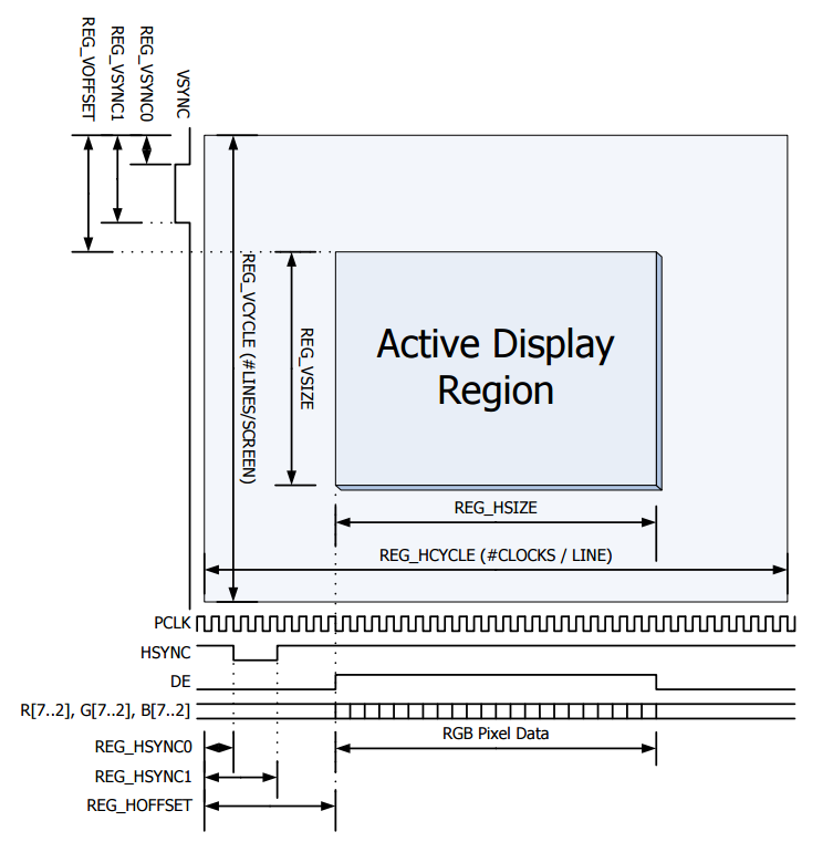
After setting, a blank screen is displayed. Further, if necessary, the configuration of the touch input and the audio channel is carried out. All these procedures are repeatedly described by the manufacturer, therefore, probably, they do not need explanations.
Display graphics primitives and widgets
After initialization, working with the display is reduced to forming the next display list and loading it onto the graphics controller. The display list is a list of commands that, as a result of execution of which, the FTDI controller displays a kind of image.
The display list begins with writing the command CMD_DLSTART to the graphics controller and ends with writing the command DISPLAY (). The display of the display list occurs by writing the standard value to the register REG_DLSWAP.
The body of the display list can contain up to 2048 instructions. All of them are simple commands like setting the color of objects and drawing graphic primitives - lines, rectangles, points, etc.
The FTDI graphics controller consists of several nodes, including the main processor, an additional graphics co-processor, audio processor, etc. The main processor of the FT800 is responsible for the execution of simple commands of the display list, but the FTDI chips allow working with more complex objects - widgets. Widgets are buttons, sliders, scales, gradients, text strings, numbers, and so on. Despite the fact that widgets are rendered by the coprocessor, simple basic functions and functions of widgets drawing can be interleaved while forming the display list.
Using the FT800 library in your own mbed project
In the last article , a draft of the project was prepared - a short program that displays a seconds counter on a virtual COM port. Today, we will connect the FT800 library to the project and will display the seconds counter on the TFT display.
Among the mbed-developers, there is already a person who dealt with the FT800 graphics controller. This same person, Peter Drescher, successfully adapted the FTDI library for mbed, provided it with an example of use and photographs. Thanks, Peter!
To use the library in your project, click on the Import library on the dedicated FT800 page , get into your compiler and select the project to which the library will be connected. Of course, for all these gestures, you must first register at developer.mbed.org.
To use the FT800 library, you need to connect the FT_Platform.h file to your main.cpp and declare a new FT800 TFT object, just like we declared a Serial class pc object in the program from the previous article. Arguments when declaring an object are board outputs on which SPI interface lines and PD and INT signals are available. Since I will run the program on three different boards, I immediately paint a pinout for all three cases:
#include "mbed.h" #include "FT_Platform.h" // SLSTK3400A FT800 TFT (PE10, PE11, PE12, PE13, PB11, PD4); // mosi, miso, sck, ss, int, pd // WIZwiki-W7500P //FT800 TFT (D11, D12, D13, D10, D9, D8); // mosi, miso, sck, ss, int, pd // ATSAMD21-XPRO //FT800 TFT (PA18, PA16, PA19, PA17, PA20, PA21); // mosi, miso, sck, ss, int, pd The FT800 class constructor itself is in the FT_Gpu_Hal.cpp file .
FT800::FT800(PinName mosi, PinName miso, PinName sck, PinName ss, PinName intr, PinName pd): _spi(mosi, miso, sck), _ss(ss), _pd(pd), _f800_isr(InterruptIn(intr)) { _spi.format(8,0); // 8 bit spi mode 0 _spi.frequency(2000000); // start with 10 Mhz SPI clock _ss = 1; // cs high _pd = 1; // PD high Bootup(); } The FT800 class designer already includes the entire TFT module initialization procedure — setting up the SPI interface and calling the Bootup () function, which describes sending a 20-millisecond pulse to the PD line, sending the desired sequence of Host commands, checking the REG_ID of the graphics controller, further setting the SPI frequency at 20 MHz, as well as setting the parameters of the TFT-display.
You can watch the code on developer.mbed.org (scroll to the bottom of the page).
It is important to note that the defaults for the parameters of a TFT display are set in the file FT_LCD_Type.h , where by default the parameters of the display of the WQVGA standard with a resolution of 480 by 272 are specified.
You will understand that the display is correctly connected and correctly initialized, if after the constructor has been tested the white screen is lit, in any other case you need to look for an error. If everything is done correctly, you can begin to form the first display list.
I will give an example of a simple program for displaying the counter of seconds, round hours and several more objects.
The only display list will consist of the following operations:
1. Start of the display list, setting the white color as the default color:
TFT.DLstart(); TFT.DL(CLEAR_COLOR_RGB(255, 255, 255)); TFT.DL(CLEAR(1, 1, 1)); 2. Set the black color, output two text lines:
TFT.DL(COLOR_RGB(0, 0, 0)); TFT.Text(11, 15, 30, 0, "Demo-project for habrahabr.ru"); TFT.Text(13, 15 + 40, 28, 0, "Using FT800 library"); 3. Setting the dark green color, the output of the graphic primitive "Rectangle":
TFT.DL(COLOR_RGB(9, 35, 5)); TFT.DL(BEGIN(RECTS)); TFT.DL(VERTEX2II(11, 105, 0, 0)); TFT.DL(VERTEX2II(11 + 275, 105 + 100, 0, 0)); 4. Set the white color, text output and the number of seconds:
TFT.DL(COLOR_RGB(255, 255, 255)); TFT.Text(11 + 10, 105 + 10, 29, 0, "Number of seconds:"); TFT.Number(11 + 10, 105 + 10 + 30, 31, 0, seconds); 5. Output of one of the supported clock widgets on FT800:
TFT.Clock(390, 105 + 70, 70, 0, 4, 20, (seconds % 60), 0); 6. Set black color, text line output:
TFT.DL(COLOR_RGB(0, 0, 0)); TFT.Text(11, 240, 28, 0, "e-mail: xk@efo.ru"); 7. Output of the “Straight Line” graphic primitive:
TFT.DL(BEGIN(LINES)); TFT.DL(LINE_WIDTH(8)); TFT.DL(VERTEX2II(11, 15 + 40 + 30, 0, 0)); TFT.DL(VERTEX2II(460, 15 + 40 + 30, 0, 0)); 8. The end of the display list, loading pictures on the display:
TFT.DL(DISPLAY()); TFT.Swap(); I pay attention that the TFT.DL () commands are the simple display list commands described above, and the TFT.Text (), TFT.Number () and TFT.Clock () commands are coprocessor instructions.
Important!
Two libraries of the same author, FT800 and FT800_2, are available for mbed graphic controllers of the FT800 series. They differ from each other only in the names of functions: in the first library the same names are used as in the materials from FTDI, and in the second all names are abbreviated:
| TFT.Ft_Gpu_CoCmd_Dlstart (); TFT.Ft_App_WrCoCmd_Buffer (CLEAR_COLOR_RGB (255, 255, 255)); TFT.Ft_App_WrCoCmd_Buffer (CLEAR (1, 1, 1)); TFT.Ft_App_WrCoCmd_Buffer (BEGIN (LINES)); TFT.Ft_App_WrCoCmd_Buffer (VERTEX2II (11, 15 + 40 + 30, 0, 0)); TFT.Ft_App_WrCoCmd_Buffer (VERTEX2II (460, 15 + 40 + 30, 0, 0)); TFT.Ft_App_WrCoCmd_Buffer (DISPLAY ()); TFT.Ft_Gpu_CoCmd_Swap (); | TFT.DLstart (); TFT.DL (CLEAR_COLOR_RGB (255, 255, 255)); TFT.DL (CLEAR (1, 1, 1)); TFT.DL (BEGIN (LINES)); TFT.DL (VERTEX2II (11, 15 + 40 + 30, 0, 0)); TFT.DL (VERTEX2II (460, 15 + 40 + 30, 0, 0)); TFT.DL (DISPLAY ()); TFT.Swap (); |
We return to the example of working with the display, the program for displaying the seconds counter on the TFT. We take as a basis the draft project from the previous article, in which, using the base library mbed, a seconds counter is displayed on the serial interface.
Output seconds counter to serial interface
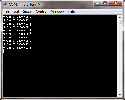
#include "mbed.h" Serial pc(USBTX, USBRX); Ticker timeKeeping; volatile uint64_t seconds = 0; void secondsCallback(void) { pc.printf("Number of seconds: %x\r\n", seconds); seconds ++; } int main() { timeKeeping.attach(&secondsCallback, 1.0f); while(1) {} } We make the appropriate changes - we connect the FT800 library, declare an object of the class FT800 and you call an infinite loop to the function that forms the display list described above.
#include "mbed.h" #include "FT_Platform.h" FT800 TFT (PE10, PE11, PE12, PE13, PB11, PD4); // mosi, miso, sck, ss, int, pd [SLSTK3400A] //FT800 TFT (D11, D12, D13, D10, D9, D8); // mosi, miso, sck, ss, int, pd [WIZwiki-W7500P] //FT800 TFT (PA18, PA16, PA19, PA17, PA20, PA21); // mosi, miso, sck, ss, int, pd [ATSAMD21-XPRO] Ticker timeKeeping; volatile uint64_t seconds = 0; /***********************************************************************************************************************/ void secondsCallback(void) { seconds ++; } /***********************************************************************************************************************/ /* Construct the screen and downloasd it to the TFT */ void drawTimeScreen(void) { TFT.DLstart(); TFT.DL(CLEAR_COLOR_RGB(255, 255, 255)); TFT.DL(CLEAR(1, 1, 1)); TFT.DL(COLOR_RGB(0, 0, 0)); TFT.Text(11, 15, 30, 0, "Demo-project for habrahabr.ru"); TFT.Text(13, 15 + 40, 28, 0, "Using FT800 library"); TFT.DL(COLOR_RGB(9, 35, 5)); TFT.DL(BEGIN(RECTS)); TFT.DL(VERTEX2II(11, 105, 0, 0)); TFT.DL(VERTEX2II(11 + 275, 105 + 100, 0, 0)); TFT.DL(COLOR_RGB(255, 255, 255)); TFT.Text(11 + 10, 105 + 10, 29, 0, "Number of seconds:"); TFT.Number(11 + 10, 105 + 10 + 30, 31, 0, seconds); TFT.Clock(390, 105 + 70, 70, 0, 4, 20, (seconds % 60), 0); TFT.DL(COLOR_RGB(0, 0, 0)); TFT.Text(11, 240, 28, 0, "e-mail: xk@efo.ru"); TFT.DL(BEGIN(LINES)); TFT.DL(LINE_WIDTH(8)); TFT.DL(VERTEX2II(11, 15 + 40 + 30, 0, 0)); TFT.DL(VERTEX2II(460, 15 + 40 + 30, 0, 0)); TFT.DL(DISPLAY()); TFT.Swap(); } /***********************************************************************************************************************/ int main() { timeKeeping.attach(&secondsCallback, 1.0f); while(1) { drawTimeScreen(); } } The project is available at developer.mbed.org .
To get the firmware file for three different debugging boards, you need, like last time , to change the target platform in the upper right corner of the compiler window, and also change the names of the I / O lines. Voila - the program compiles and runs on all three boards.
The next article will describe the process of creating and connecting to our project a library for the temperature and relative humidity sensor HYT-271. We will slowly approach the full-fledged application, whose work is shown on video.
Conclusion
In conclusion, I traditionally thank the reader for his attention and remind you that questions about the use of products, about which we write on Habré, can also be asked by email, specified in my profile.
Source: https://habr.com/ru/post/309918/
All Articles