ExcelArt - isometry "for free". Draw a pseudo-volume phone without 3D and Photoshop

Is it possible to get a pseudo-volumetric image without 3D programs? “Of course,” you say, “you take, strain, and draw from scratch.” And if without "you take, you strain and draw"? And if at all without any special knowledge? Is it possible to get isometric objects without spending time on render? Is there any digital illustration out of the usual graphics programs? I will answer these and other questions in my article devoted to the new method of creating digital illustrations - ExcelArt.
Part 1. A unique method of creating illustrations
The first part of the article is theoretical. Here you will find general information about what this method is, how it appeared and why it is needed. The second part is practical. It will help on a specific example to see how it works. A step-by-step tutorial is waiting for you in it, having executed it, you can easily create a realistic phone with your own design on the screen.
A brief background on creative tools
Surprisingly, the era of digital technology presented modern designers and illustrators with not so many tools. And, despite the fact that their possibilities are extremely wide, they still have their limits. It's no secret that we all work today in the same photoshop, illustrators and 3D-max. This in itself is not bad, the programs indicated are excellent. Nevertheless, the same tools give similar methods of working with them and, accordingly, similar results. It seems that each “fresh” work of a new author is somewhat similar to the previous ideas of the old masters. The situation is only complicated by universal informational globalization: we all look at other people's work and, one way or another, we adopt the best practices and techniques from each other. Of course, this is how progress is made, but the other side of the coin is some monotony.
I believe that a truly loving illustrator or designer simply has to constantly be in search of new tools, styles, and work techniques. Without this, his professional development is impossible. Without this, progress in the design world is also unthinkable.
')
Guided by the idea of finding new creative tools, I conducted a kind of experiment. I tried to create a digital illustration without using familiar graphics programs. After a certain number of attempts, I came across something completely unique.
Easy and fast isometry without 3D
I noticed that in Microsoft Excel you can create and combine simple pseudo-volume figures. Having enough ingenuity and imagination, with the help of this small function it is quite possible to draw interesting bright isometric illustrations.
As you know, it is better to see once than hear a hundred times. Therefore, in order to save the time of dear readers, I will simply show a video in which the whole process of creating a picture in MS Excel is clearly visible from beginning to end.
What does it give to designers and illustrators
In many cases, ExcelArt is a big saving of time, effort, and nerves. For example, when working in the matte-paint technique, there is often a need to obtain isometric figures for subsequent post-processing in Photoshop. Running a few cubes and pyramids stacked in a certain order, a 3D editor is like shooting a gun at sparrows. In addition, not everyone has enough knowledge of 3D, and the "Maya" with "max" are not on every computer.
When problems go beyond cubes, and you need to draw, for example, several buildings, such a task may also require a lot of time. Although with a little practice, doing the same thing in Excel is much faster.
I myself once became a victim of a pseudo-volume task. I needed to get pseudo-volume letters in a vector. When I tried to do this with standard tools in Illustrator, he first calculated the image for a few minutes, and then gave me a bunch of broken lines. To draw the same with gradients and contours was unrealistically laborious. Above the challenge threatened failure. Excel Excel saved! In just a few seconds (!) I made bulk text in Excel. And, by the way, the result was excellently exported from there to the “chandelier” (after all, I needed a vector at the exit).
What does it give to ordinary people
ExcelArt is extremely easy to learn. No wonder, because all the work is being done in a familiar table editor, and not in some complex graphic package with a sophisticated interface. Moreover, the work involves a small number of tools, one can figure out how to use them without spending a lot of time.
As an example, I will cite several illustrations made exclusively by the ExcelArt method without further post-processing.

And now, in the second part of the article, you yourself can try to create a full-fledged digital illustration. Do not be afraid of the size of the tutorial, all the steps in it are intuitive and similar to each other.
Part 2. Tutorial

In the first part of the article, you learned what the uniqueness and advantages of the new method of creating digital illustrations, ExcelArt, are. It's time to practice. Let's try together to create a full image - the phone.
Why was the phone chosen? The fact is that a significant share of the work of a modern IT specialist is the creation of mobile content. All developers of mobile games and applications, as well as UI-designers love to show their products in their natural environment. Based on this, it will always be convenient to have a small mocap that will help you quickly and easily demonstrate your mobile prototype. This is the mocap with the phone we will do in this lesson.
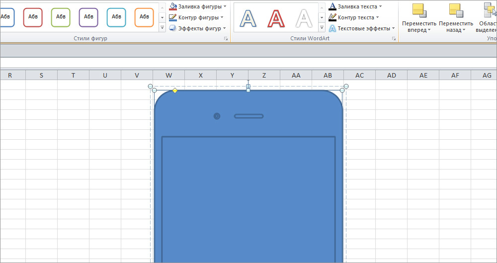
1. Let's start by creating the front of the phone. To do this, open MS Excel, select the Insert> Shapes> Rounded Rectangle tab (20.29 x 9.97 cm) in the top panel. Round the corners with a yellow diamond in the upper left corner of the shape, as in the image below.

To make it easier for you to navigate in proportions, in parentheses, I will indicate the size of all created objects. Once you have created a shape, you can change the dimensions in the Format> Size tab.
Attention! Do not create a shape in the upper left corner of the page. Later, when you start adding other objects and working with isometry, you may have problems with the location of elements. Note that I made my rectangle closer to the center of the page (coordinates W69).
2. Take the screen. First we create the screen itself, it is done in the same way as the previous element, that is, using the top tab Insert> Shapes> Rectangle (15.74 x 9.21 cm). In this case, you do not need to round corners. Next, do the speaker: Insert> Shapes> Rounded rectangle (0.18 x 1.5 cm), its corners need to be rounded to the maximum. Then create a button: Insert> Shapes> Oval (1.5 x 1.5 cm).

3. The front camera is created by two Ovals: the lower one with a larger diameter (0.29 x 0.29 cm) and the upper one with a smaller diameter (0.14 x 0.14 cm). In order to continue to work with them further, these two Ovals need to be grouped. To do this, hold down the Shift key, select the ovals by clicking on each of them. Shift need to let go. Then, clicking on any of the ovals with the right mouse button, call the menu and select the items: Group> Group.

4. Now we need to align all objects relative to each other. Let's start with the camera and speaker. It is necessary that they are on the same line. To do this, hold down the Shift key, select the camera and speaker, and in the top tab, select: Format> Arrange> Align> Align in the middle. Next, group the speaker and camera as you did with the ovals in the previous step.

After that, holding down the Shift key, select all objects (case, screen, button, grouped speaker and camera) and align them on one axis by selecting: Format> Arrange> Align> Center Align. All selected and aligned objects you now need to group in one.

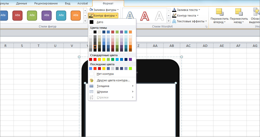
5. It's time to give the picture a color. Click three times with the left mouse button on the phone body, so that it is the body that is highlighted, and not the entire grouped object. The indicator of the correct choice will be two blue strokes around the objects: one external dotted and the other internal solid.
Next, in the top tab - Format> Fill Shape - select black. To remove the outline of the phone, do the following: Format> Shape Outline> No Outline.

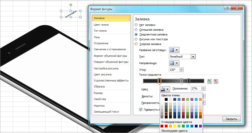
6. Painting the loudspeaker and camera is more complicated, as they are painted not with a solid color, but with gradients. To do this, select the speaker (do not forget that all objects are grouped, and you only need to select the speaker with a triple click, not the whole group), right-click the speaker and select - Format figure. In the pop-up window that appears, select the tab - Fill> Gradient Fill. Create a gradient with the following settings: type - linear; angle of 90; the left point of the gradient is the second gray color from the bottom of the second column with a brightness of 15%; the right point of the gradient is the third gray color at the bottom of the second column with a brightness of 25%. And, of course, do not forget to remove the outline, as in the previous step: Format> Shape Outline> No Outline.

In the same way, paint over the front camera. First select the lower oval of a larger diameter. Its gradient settings are as follows: type — linear; angle of 300; the left point of the gradient is the second gray color from the bottom of the second column at the position of 41% with a brightness of 15%; the right point of the gradient is the third color from the bottom of the second column with a brightness of 25%.

Now select the top oval of a smaller diameter. Make a gradient with the following settings: type - linear; angle 0⁰; the left point of the gradient is the third blue color from the bottom of the fourth column with a brightness of 40%; the right point of the gradient is the second blue color from the bottom of the fourth column with a brightness of 25%.

7. With the screen, everything is much simpler. The color of the screen is as follows: Format> Fill> white color. To paint the contour, select: Format> Contour of the figure> second gray color from the bottom of the second column.
Unlike all previous objects, the button has no fill, but the outline is colored gradient. To set it in the Format window, select: Line color> Gradient line. For the contour, we need four gradient points. They can be created by clicking the left mouse button on the gradient bar. Note that the colors of all the points of the gradient are the same, only the position and brightness will be different. So, the gradient settings are as follows: type - linear; angle of 50⁰; gradient color - the second gray color from the bottom of the second column; the first point of the gradient - position 30%, brightness 18%; the second point of the gradient - position 48%, brightness 30%; the third point of the gradient - position 62%, brightness –100%; The fourth point of the gradient is the position of 70%, the brightness is 15%.

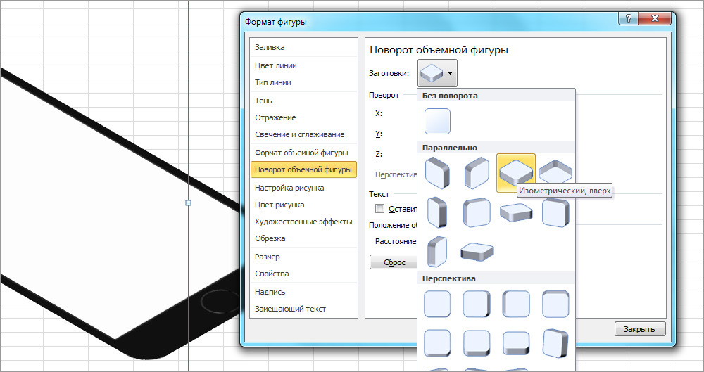
8. It is time to give objects an isometric view. Click on a grouped shape once to highlight it, right-click to call the already familiar Figure Format window. Next, select: Rotate a solid shape> Workpiece> Parallel> Isometric, top. Do not close the Format Shape window.
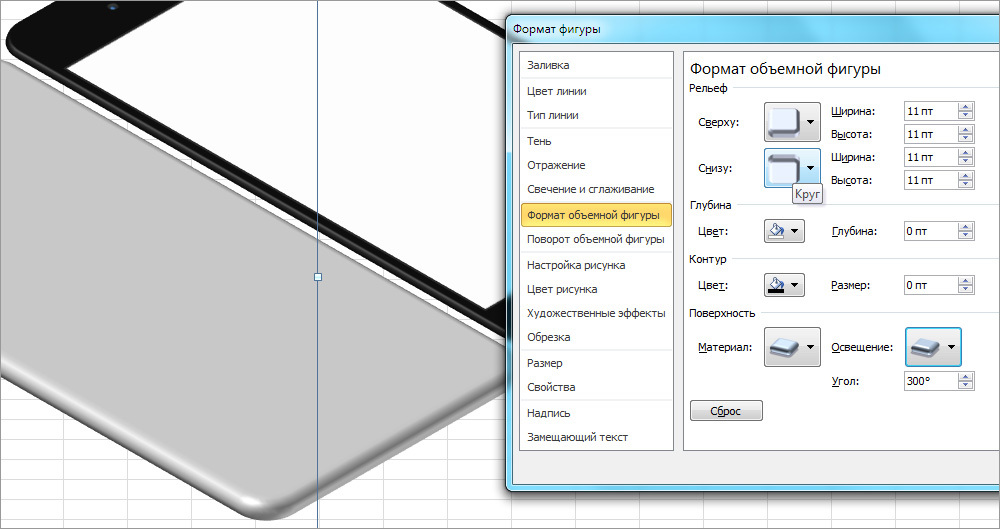
Select the black rectangle of the case and go to the Format tab of the volumetric figure. Specify the following terrain settings for the body: from above — a circle, width 4 pt, height 5 pt. Depth, surface and contour do not need to be changed. If everything is done correctly, small gray shadows should appear at the two edges of the rectangle.

9. Now let's create the metal part of the body. Click three times on the black rectangle of the case, selecting it, and copy it by pressing Ctrl + C. After that, deselect by clicking on any empty cell of the sheet, and insert a rectangle by pressing Ctrl + V.
Fill the rectangle with light gray (the third color from the bottom of the first column) and slightly increase it (20.53 x 10.09 cm). In the Format tab of a volumetric figure, make the following relief settings: from above — a circle of 11 pt in width and height; from below — a circle of 11 pt in width and height. Note that in the same tab you need to change the angle of illumination: Surface> Illumination> Angle> 300⁰. Depth and contour do not touch.
To place the metal part of the case under the black one, click on it with the right mouse button and select the following items: To the back> To the back.

10. At this stage, we have reviewed all the basic techniques for generating objects necessary for creating an isometric telephone. Almost all of the following elements will be created in exactly the same way as all previous construction details.
Start making the bottom hole block with a speaker. Make six identical Ovals (0.2 x 0.2 cm). Align them in the middle and group them. Next, select: Shape format> Rotate a solid shape> Workpieces> Parallel> Isometric, right-up.

Give each oval the same gradient. This time we need three gradient points. As in the previous case, the color of all points is the same - the second gray color is from the bottom of the second column. The remaining settings are as follows: type - linear; angle of 130⁰; the first point of the gradient - position 27%, brightness 15%; the second point of the gradient - position 63%, brightness 50%; the third point of the gradient is the position of 75%, brightness –15%.
Now you need to select the outline thickness by clicking on the top tab: Format> Shape Outline> Thickness> 0.5 pt. In the same paragraph, select the color - the first gray color from the bottom of the first column.
11. Now we will deal with a hole for charging and bolts near it. Each bolt consists of two figures. The bottom figure is Oval (0.2 x 0.2 cm), light gray (second color from the bottom of the first column) without contour. The top figure is a five-pointed star. To create it, select the Insert tab> Shapes> 5-pointed star (0.15 x 0.15 cm). Color: black without contour. Both figures must be highlighted and aligned relative to each other in the center and in the middle, as well as grouped. The bolts are absolutely the same, so you can only make one and the other just copy side by side.
Hole for charging, as you probably already guessed, this is a rounded rectangle (0.32 x 1.06 cm), the corners of which are rounded to the maximum. The color of all three gradient points is the same as in the previous step. The gradient settings are similar: type - linear; angle of 130⁰; the first point of the gradient is the position 0%, brightness 15%; the second point of the gradient is the position 29%, brightness 50%; The third point of the gradient is the position of 94%, the brightness is –15%. The contour thickness is 1 pt, the color is the second gray color at the bottom of the first column.
After you make the bolts and the charging hole, align them in the middle and select: Shape format> Rotate the solid shape> Workpieces> Parallel> Isometric, right-side up.

12. The last two Ovals on the bottom are the headphone input (the one that is larger) and the microphone hole.
The microphone hole is an exact copy of the speaker holes, just copy one of them.
The headphone input is made from Oval (0.48 x 0.48 cm) without contour. The color of the gradient points is the same: the second is the gray color at the bottom of the second column. The gradient settings are: type - linear; angle of 30⁰; the first point is the position of 7%, brightness –18%; The second point of the gradient is the position of 100%, the brightness is 37%.
As always, we align both holes in the middle, group them and set the resulting rotation group: Format of the figure> Rotation of the solid figure> Blanks> Parallel> Isometric, right up.
13. It remains to make the sidebar. The mute button consists of two rounded up rectangles. The bottom rectangle (0.3 x 0.85 cm) of dark gray color (the third color from the bottom of the second column) without contour. The upper rectangle (0.16 x 0.85 cm) in light gray (the third color from the bottom of the first column) without contour. Go to the Shape Format> Volumetric Shape Format tab and specify the following settings for the top rectangle — relief: top — angle, width 0.5 pt, height 1 pt; depth: depth 1.5 pt; surface: material - standard “plastic”, lighting - neutral “three points”, illumination angle: 170⁰. The lower rectangle does not require any settings. To rotate the rectangles in isometric projection, select for each of them: Shape format> Rotate volumetric shape> Workpieces> Parallel> Isometric, left down.

Attention! Do not group the rectangles until you have made each of them completely, otherwise after adjusting the format of the volume you may have problems with overlapping one rectangle with another.
14. The volume buttons are made of three rounded rectangles. The ovals of the buttons themselves (0.29 x 1.43 cm) have exactly the same settings as the mute button in the previous step. The rounded rectangle under them (0.36 x 3.39 cm) does not have a contour. The gradient settings for it are as follows: the color of both points is the third dark gray color from the bottom of the second column; type - linear; angle of 90; the first point of the gradient is the position 0%, brightness 29%; The second point of the gradient is the position of 100%, the brightness is 75%. Rotate all ovals: Shape format> Rotate a solid shape> Workpieces> Parallel> Isometric, left down.
After you have done all the details of this block, do not forget to group them for easy insertion and dragging.
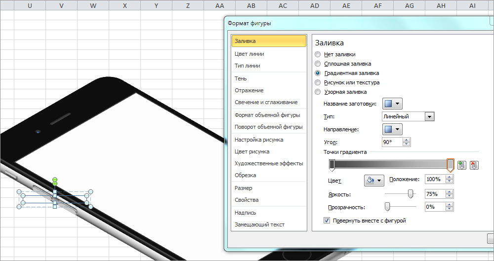
15. Gray bars on the side of the body are obtained from two figures. Block diagram (Insert> Figures> Block diagram: saved data), size 0.5 x 0.4 cm each, rotation of the figure: Format of the figure> Rotation of the solid figure> Blanks> Parallel > Isometric, left down.

Gradient settings: the color of both points - the second light gray color from the bottom of the first column; type - linear; angle of 100⁰; the first point of the gradient is the position 0%, brightness –35%, transparency 30%; The second point of the gradient is the position 100%, brightness –63%, transparency 0%.
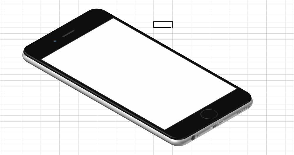
16. Our phone is ready. It remains only to insert the image into the screen. Select the white rectangle of the screen, right-click to open: Shape format> Fill> Picture or texture> Paste from: File. Then select the image on your computer that you want to add to the phone screen, and click the Insert button. I inserted a pre-shot screen mail application Mail.Ru. You can add a design layout to your application or any other image.

17. In order for the picture to have a complete look, it is necessary to paint over the background. To do this, simply select the empty cells behind the phone and select the appropriate fill color in the upper tab: Home> Font> Fill Color.

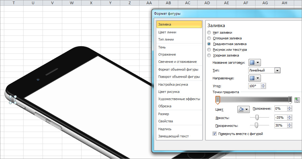
Having finished the image and looking at the result, I realized that the phone lacked a small shadow to make it more convincing. You ask: "Is it possible to do this in Excel?" It can be much more, but we will stop there.
Select the bottom gray rounded rectangle (case) and right-click to open the Format Shape window. In the Shadow tab, list the following settings: color - black, transparency - 62%, size - 99%, blur - 11 pt; angle - 60⁰; distance - 3 pt.

18. The last question that we have to solve is how to get the file with the finished image, which we have been working on for so long. There are several ways to solve this problem. I will tell one the most simple and logical - just take a screenshot.
The desktop version of Mail.Ru Cloud has a great screenshot. Press Shift + Ctrl + 6, select the part of the screen with the image of the phone and click Finish. The link to the image will immediately go to your clipboard, and the png image itself will be in your Cloud in the Screenshots folder. So, quickly and conveniently, and do not need anything separately cut and save.


I hope you enjoyed the tutorial, and now you can fully appreciate all the advantages of creating digital illustrations using the ExcelArt method. And if you have any questions, feel free to ask them in the comments. And be sure to show what you got if you use my tutorial.
Source: https://habr.com/ru/post/309480/
All Articles