STM32 USB Mass Storage Bootloader
It is known that the software can be added forever, and all sorts of shortcomings on the board are completely corrected revisions so to the third. And if you can’t do anything with iron, then you have come up with a good way to bypass the space and time restrictions to update the firmware - Bootloader .
The loader is convenient and useful, isn't it? And if the loader is its own implementation, then it is even more convenient, useful and flexibleand not stable . And of course, very cool!
It is also a great opportunity to go deep and study the features of the used computer - in our case, an STM32 microcontroller with an ARM Cortex-M3 core.
')
In fact, the bootloader is simpler than it seems at first glance. As proof, under the cut we'll build our own USB Mass Storage Bootloader!
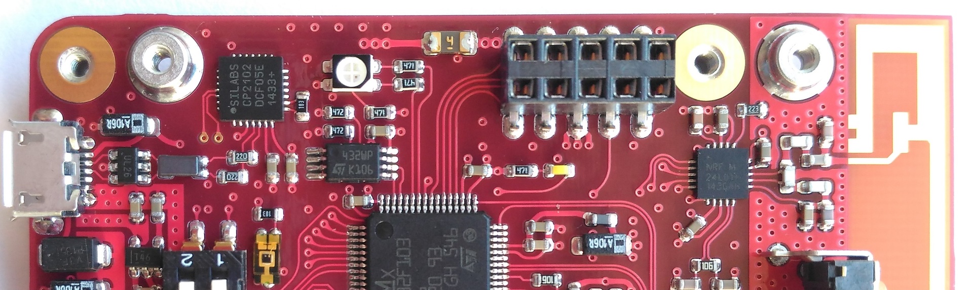

We will work with a homemade board on a microcontroller (hereinafter referred to as MK) STM32F103RET . In order not to overflow the publication with unnecessary pictures, I will give a truncated scheme of this piece of iron:

When writing a bootloader, I was guided by the following principles:
Drove off
Since we will work with our own FLASH-memory STM32 constantly and often, it is worth explaining at once some key points related to this fact.
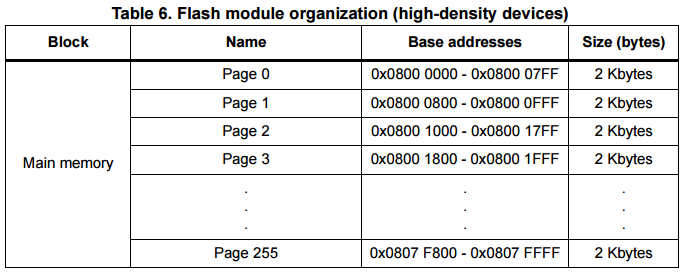
Used MK contains 512 Kbyte FLASH memory. It is paginated by 2048 bytes:
For us, this means that writing a few bytes to an arbitrary address just won't work. When writing to FLASH, it is only possible to reset the desired cells, but setting units is performed using the erase operation, the minimum possible amount for which is one page. To do this, use the FLASH_AR register, in which it is enough to write down any address within the page we need - and it will be filled with 0xFF bytes. And still you need to remember to unblock FLASH before erasing / writing operations.
Virtually split FLASH into several areas, each of which will have its own, special purpose:

USER_MEM will match MSD_MEM in size. This is logical, because two opposite cases will give either a lack of memory in USER_MEM , or an excess.
And now everything is the same, only for the machine (and the convenience of the programmer):
Having agreed on the division of memory into areas, it's time to figure out how it all will interact. Draw a flowchart:

According to this algorithm, the bootloader has two main modes, working independently of each other, but having a common resource - a piece of MSD_MEM memory. However, even its use occurs at different points in time, which positively affects the stability of the bootloader and simplifies the programming and debugging process.
Consider each of the modes in more detail:
It starts immediately after entering main () , if the corresponding launch condition is met, the button is pressed. On my board, this is the upper slider of the on-off switch (which, by the way, is wound up on the legs of the MK BOOT0 and BOOT1 (PB2) - this allows you to use the hardware UART loader MK if necessary).
Work in the Mass Storage mode is taken from examples from STMicroelectronics ( STM32_USB-FS-Device_Lib_V4.0.0 ), which can be downloaded from their website. There we are shown how it is necessary (or vice versa, it is not necessary - the attitude to the libraries from ST among people is not always positive) to work with a microcontroller and a memory card connected via SDIO interface in USB MSD mode. The example implements two Bulk In / Out Endpoint'a with a packet length of 64 bytes, as well as a set of necessary for the operation of SCSI commands. We throw out functions related to SD cards or NAND memory (mass_mal.c / .h) from there and replace them with work from internal FLASH:
If everything is done correctly, when connected, the computer will identify our product as a USB Mass Storage Device and will offer to format it, because In the area of MSD_MEM there is garbage. It is worth noting that in this mode of operation, the MC is simply an intermediary between the host and FLASH memory, and the operating system independently decides what data and at what addresses will be stored on our drive.
Let's format the disk and see how it affected the MSD_MEM area :
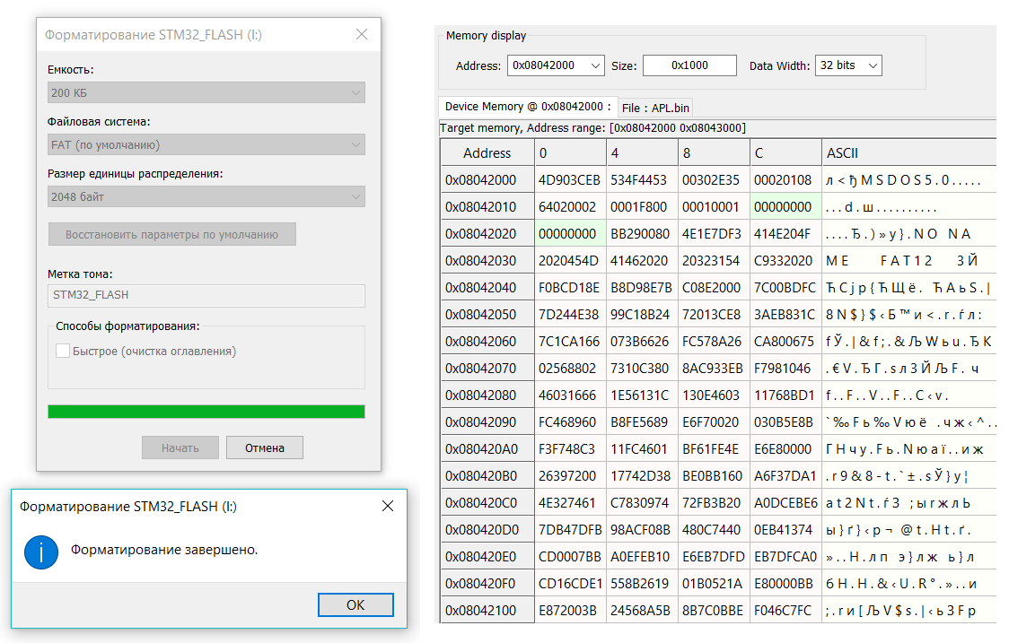
The volume is the same, the size of the Windows sector has determined the correct, the zero sector is bootable, the location in memory corresponds to what was intended. Files are written, read, do not disappear after turning off the power - a full-fledged flash drive with 200 Kbyte!
Run if firmware update is not required. That is, the normal operation of the device. In it, we have to perform several basic actions necessary for the successful launch of user software. Basic - because if necessary, you can supplement the work of the bootloader with all sorts of features, such as encryption, integrity checking, debugging messages, etc.
Suppose we have already created using Windows a file system on a USB drive and loaded the necessary software. Now it would be nice to see the contents of the carrier with the “eyes” of the MK, which means we are going to visit fellow ChaN for FatFS (a module of a simple FAT file system designed for small embedded systems on microcontrollers). Download, throw in the project, register the function of reading the necessary data from the disk:
disk_write () is not needed and is left blank, because the mounted file system is Read Only. This can also be set in the ffconf.h configuration file, additionally disabling all unnecessary and unused functions.
Then everything is more or less obvious: we mount the file system, open the firmware file, and start reading. Initially, it was implemented in such a way that the main storage location of the firmware is MSD_MEM , and the microcontroller overwrites its FLASH memory each time it is turned on. No firmware - debug message of the absence and while (TRUE) . There is a firmware - we throw it in USER_MEM . However, the obvious disadvantage of this solution is that the resource of erasing / writing FLASH memory has a limit and it would be foolish to gradually and consciously kill the product.
Therefore, we compare "APP.BIN" and USER_MEM , stupidly, byte by byte. Perhaps a comparison of the hash sums of the two arrays would look more elegant solution, but certainly not the fastest. Let's look again at main () :
If during the comparison process we did not reach the end of the cycle, then the firmware is different and it's time to update USER_MEM with CopyAppToUserMemory () . Well, and then it would be nice to destroy the traces of the bootloader by calling PeriphDeInit () and then GoToUserApp () . But this is a bit later, but for now - the copying process:
Copy will be in blocks of 512 bytes. 512 - because I saw somewhere that when the buffer size is larger than this value, f_read () can mess up. I checked this moment - everything worked for me and with a larger buffer. But just in case, left 512 - why not? We save RAM, and it does not affect the speed, moreover, it is performed once - at the moment the device is turned on and only under the condition that it is time to update the firmware.
Pre-erase in FLASH memory place under the file. The size of the erased area is equal to the number of pages in memory, which will be fully occupied by “APP.BIN” + one more (which is not completely). And also, virtually we beat the firmware file on “body” and “tail”, where “body” is the maximum possible piece of the file, which includes an integer number of blocks of 512 bytes, and “tail” is everything else.
It seems that all binary firmware files are multiples of 4th bytes. I wasn’t sure about that (and still), so just in case - if the firmware is not a multiple of sizeof (u32) - we supplement it with 0xFF bytes. I repeat: it seems that this does not need to be done - but the operation is harmless for multiple sizeof (u32) binaries, so let's leave it.
Getting close. We deinitialize all the used peripherals with the PeriphDeInit () function (and there is almost nothing at all - GPIO for the mode select button and, if desired, the UART for outputting debug messages; no interrupts are used).
The final life stage of the bootloader is the beginning of the user firmware:
Only 5 lines, but how much is happening!
In the ARM Cortex M3 core, when an exception occurs, the corresponding handler is called for it. To determine the starting address of the exception handler, a vector table mechanism is used. The vector table is an array of data words within system memory, each of which is the starting address of one type of exception. The table is moved and the movement is controlled by a special VTOR register in SCB (System Control Block) (In the manual, it sounds cooler, but I broke down: The vector table is relocatable, and the relocation is controlled by the NVIC ). After RESET, the value of this register is 0, that is, the vector table lies at the address 0x0 (for the STM32F103 in the startup file, we independently move it to 0x08000000). And what is very important for us, the order is as follows:
All this together, plus a bit of magic with a pointer to the function, and Alice jumps after the rabbit.
Now check if it works at all. Let's write a simple LED blinking program with cycles in main () and a couple of interrupts (SysTick and TIM4):
By the way, you need to remember to fix a couple of things in the project, without which nothing will work:
And this is how this code is executed (well, maybe not everyone has seen the LEDs blink ...):
And this is how the download log of this firmware in the MK via the bootloader looks like:
Let's sum up. The bootloader turned out! And even works. With the output of debug messages in the UART, it occupies 31,684 bytes of FLASH memory, without - 25,608 bytes. Not so little, if you also consider how much memory you need to give for Mass Storage disk. Sources and working draft (Atollic TrueSTUDIO) can be viewed on Bitbucket .
Thanks for attention!
The loader is convenient and useful, isn't it? And if the loader is its own implementation, then it is even more convenient, useful and flexible
It is also a great opportunity to go deep and study the features of the used computer - in our case, an STM32 microcontroller with an ARM Cortex-M3 core.
')
In fact, the bootloader is simpler than it seems at first glance. As proof, under the cut we'll build our own USB Mass Storage Bootloader!
We will work with a homemade board on a microcontroller (hereinafter referred to as MK) STM32F103RET . In order not to overflow the publication with unnecessary pictures, I will give a truncated scheme of this piece of iron:
When writing a bootloader, I was guided by the following principles:
- Your bootloader is very necessary and enough to put it off in the TODO list, it's time to sit down and do it;
- Bootloader should have a user-friendly program download interface. No drivers, third-party programs, adapter boards and MGTF wiring harnesses to the target device. What could be simpler than an automatically detected USB flash drive?
- To work in bootloader mode, the microcontroller needs minimal hardware binding (in fact, only USB, quartz and a button);
- The size of the boot is not important. It is important, of course, but we will not pursue the goal of squeezing it into a couple of kilobytes. Without a pang of conscience, we will raise the USB stack, work with the file system, push printf () through the line and generally deny ourselves nothing (hello, Standard Peripheral Libraries !);
Drove off
Little FLASH
Since we will work with our own FLASH-memory STM32 constantly and often, it is worth explaining at once some key points related to this fact.
Used MK contains 512 Kbyte FLASH memory. It is paginated by 2048 bytes:
For us, this means that writing a few bytes to an arbitrary address just won't work. When writing to FLASH, it is only possible to reset the desired cells, but setting units is performed using the erase operation, the minimum possible amount for which is one page. To do this, use the FLASH_AR register, in which it is enough to write down any address within the page we need - and it will be filled with 0xFF bytes. And still you need to remember to unblock FLASH before erasing / writing operations.
Virtually split FLASH into several areas, each of which will have its own, special purpose:
- BOOT_MEM - the memory area allocated for the bootloader;
- USER_MEM - here we will store (and execute from here the same) user firmware. Obviously, it now has a limit of 200 Kbyte;
- MSD_MEM - and there will be a MASS STORAGE disk, where you can throw the firmware using the computer and your favorite OS;
- OTHER_MEM - well, let's leave some more space just in case;
USER_MEM will match MSD_MEM in size. This is logical, because two opposite cases will give either a lack of memory in USER_MEM , or an excess.
And now everything is the same, only for the machine (and the convenience of the programmer):
#define FLASH_PAGE_SIZE 2048 //2 Kbyte per page #define FLASH_START_ADDR 0x08000000 //Origin #define FLASH_MAX_SIZE 0x00080000 //Max FLASH size - 512 Kbyte #define FLASH_END_ADDR (FLASH_START_ADDR + FLASH_MAX_SIZE) //FLASH end address #define FLASH_BOOT_START_ADDR (FLASH_START_ADDR) //Bootloader start address #define FLASH_BOOT_SIZE 0x00010000 //64 Kbyte for bootloader #define FLASH_USER_START_ADDR (FLASH_BOOT_START_ADDR + FLASH_BOOT_SIZE) //User application start address #define FLASH_USER_SIZE 0x00032000 //200 Kbyte for user application #define FLASH_MSD_START_ADDR (FLASH_USER_START_ADDR + FLASH_USER_SIZE) //USB MSD start address #define FLASH_MSD_SIZE 0x00032000 //200 Kbyte for USB MASS Storage #define FLASH_OTHER_START_ADDR (FLASH_MSD_START_ADDR + FLASH_MSD_SIZE) //Other free memory start address #define FLASH_OTHER_SIZE (FLASH_END_ADDR - FLASH_OTHER_START_ADDR) //Free memory size Having agreed on the division of memory into areas, it's time to figure out how it all will interact. Draw a flowchart:
According to this algorithm, the bootloader has two main modes, working independently of each other, but having a common resource - a piece of MSD_MEM memory. However, even its use occurs at different points in time, which positively affects the stability of the bootloader and simplifies the programming and debugging process.
- The first mode is responsible for receiving and storing user software in the MSD_MEM area , which is available as an external drive.
- The second mode checks MSD_MEM for the presence of a file named “APP.BIN” , checks its integrity, authenticity, and also moves to USER_MEM if it is empty or if the firmware “APP.BIN” is more recent.
Consider each of the modes in more detail:
USB Mass Storage Device
It starts immediately after entering main () , if the corresponding launch condition is met, the button is pressed. On my board, this is the upper slider of the on-off switch (which, by the way, is wound up on the legs of the MK BOOT0 and BOOT1 (PB2) - this allows you to use the hardware UART loader MK if necessary).
int main (void)
int main(void) { Button_Config(); if(GPIO_ReadInputDataBit(BUTTON_PORT, BUTTON_PIN) == SET) //Bootloader or Mass Storage? { LED_RGB_Config(); USB_Config(); Interrupts_Config(); USB_Init(); while(TRUE); } //Bootloader mode } Work in the Mass Storage mode is taken from examples from STMicroelectronics ( STM32_USB-FS-Device_Lib_V4.0.0 ), which can be downloaded from their website. There we are shown how it is necessary (or vice versa, it is not necessary - the attitude to the libraries from ST among people is not always positive) to work with a microcontroller and a memory card connected via SDIO interface in USB MSD mode. The example implements two Bulk In / Out Endpoint'a with a packet length of 64 bytes, as well as a set of necessary for the operation of SCSI commands. We throw out functions related to SD cards or NAND memory (mass_mal.c / .h) from there and replace them with work from internal FLASH:
u16 MAL_Init (u8 lun)
u16 MAL_Init(u8 lun) { switch (lun) { case 0: FLASH_Unlock(); break; default: return MAL_FAIL; } return MAL_OK; } u16 MAL_Read (u8 lun, u32 memOffset, u32 * readBuff)
u16 MAL_Read(u8 lun, u32 memOffset, u32 *readBuff) { u32 i; switch (lun) { case 0: LED_RGB_EnableOne(LED_GREEN); for(i = 0; i < MassBlockSize[0]; i += SIZE_OF_U32) { readBuff[i / SIZE_OF_U32] = *((volatile u32*)(FLASH_MSD_START_ADDR + memOffset + i)); } LED_RGB_DisableOne(LED_GREEN); break; default: return MAL_FAIL; } return MAL_OK; } u16 MAL_Write (u8 lun, u32 memOffset, u32 * writeBuff)
u16 MAL_Write(u8 lun, u32 memOffset, u32 *writeBuff) { u32 i; switch (lun) { case 0: LED_RGB_EnableOne(LED_RED); while(FLASH_GetStatus() != FLASH_COMPLETE); FLASH_ErasePage(FLASH_MSD_START_ADDR + memOffset); for(i = 0; i < MassBlockSize[0]; i += SIZE_OF_U32) { while(FLASH_GetStatus() != FLASH_COMPLETE); FLASH_ProgramWord(FLASH_MSD_START_ADDR + memOffset + i, writeBuff[i / SIZE_OF_U32]); } LED_RGB_DisableOne(LED_RED); break; default: return MAL_FAIL; } return MAL_OK; } If everything is done correctly, when connected, the computer will identify our product as a USB Mass Storage Device and will offer to format it, because In the area of MSD_MEM there is garbage. It is worth noting that in this mode of operation, the MC is simply an intermediary between the host and FLASH memory, and the operating system independently decides what data and at what addresses will be stored on our drive.
Let's format the disk and see how it affected the MSD_MEM area :
The volume is the same, the size of the Windows sector has determined the correct, the zero sector is bootable, the location in memory corresponds to what was intended. Files are written, read, do not disappear after turning off the power - a full-fledged flash drive with 200 Kbyte!
Bootloader
Run if firmware update is not required. That is, the normal operation of the device. In it, we have to perform several basic actions necessary for the successful launch of user software. Basic - because if necessary, you can supplement the work of the bootloader with all sorts of features, such as encryption, integrity checking, debugging messages, etc.
Suppose we have already created using Windows a file system on a USB drive and loaded the necessary software. Now it would be nice to see the contents of the carrier with the “eyes” of the MK, which means we are going to visit fellow ChaN for FatFS (a module of a simple FAT file system designed for small embedded systems on microcontrollers). Download, throw in the project, register the function of reading the necessary data from the disk:
DRESULT disk_read (BYTE pdrv, BYTE * buff, DWORD sector, UINT count)
DRESULT disk_read ( BYTE pdrv, /* Physical drive nmuber to identify the drive */ BYTE *buff, /* Data buffer to store read data */ DWORD sector, /* Sector address in LBA */ UINT count /* Number of sectors to read */ ) { u32 i; for(i = 0; i < count * SECTOR_SIZE; i++) { buff[i] = *((volatile u8*)(FLASH_MSD_START_ADDR + sector * SECTOR_SIZE + i)); } return RES_OK; } disk_write () is not needed and is left blank, because the mounted file system is Read Only. This can also be set in the ffconf.h configuration file, additionally disabling all unnecessary and unused functions.
Then everything is more or less obvious: we mount the file system, open the firmware file, and start reading. Initially, it was implemented in such a way that the main storage location of the firmware is MSD_MEM , and the microcontroller overwrites its FLASH memory each time it is turned on. No firmware - debug message of the absence and while (TRUE) . There is a firmware - we throw it in USER_MEM . However, the obvious disadvantage of this solution is that the resource of erasing / writing FLASH memory has a limit and it would be foolish to gradually and consciously kill the product.
Therefore, we compare "APP.BIN" and USER_MEM , stupidly, byte by byte. Perhaps a comparison of the hash sums of the two arrays would look more elegant solution, but certainly not the fastest. Let's look again at main () :
int main (void)
int main(void) { Button_Config(); if(GPIO_ReadInputDataBit(BUTTON_PORT, BUTTON_PIN) == SET) //Bootloader or Mass Storage? { //USB MSD mode } FATFS_Status = f_mount(&FATFS_Obj, "0", 1); if(FATFS_Status == FR_OK) { FILE_Status = f_open(&appFile, "/APP.BIN", FA_READ); if(FILE_Status == FR_OK) { appSize = f_size(&appFile); for(i = 0; i < appSize; i++) //Byte-to-byte compare files in MSD_MEM and USER_MEM { f_read(&appFile, &appBuffer, 1, &readBytes); if(*((volatile u8*)(FLASH_USER_START_ADDR + i)) != appBuffer[0]) { //if byte of USER_MEM != byte of MSD_MEM break; } } if(i != appSize)//=> was done "break" instruction in for(;;) cycle => new firmware in MSD_FLASH { CopyAppToUserMemory(); } FILE_Status = f_close(&appFile); FATFS_Status = f_mount(NULL, "0", 1); PeriphDeInit(); GoToUserApp(); } else //if FILE_Status != FR_OK { if(FILE_Status == FR_NO_FILE) { //No file error } else //if FILE_Status != FR_NO_FILE { //Other error } FATFS_Status = f_mount(NULL, "0", 1); while(TRUE); } } else //FATFS_Status != FR_OK { //FatFS mount error while(TRUE); } } If during the comparison process we did not reach the end of the cycle, then the firmware is different and it's time to update USER_MEM with CopyAppToUserMemory () . Well, and then it would be nice to destroy the traces of the bootloader by calling PeriphDeInit () and then GoToUserApp () . But this is a bit later, but for now - the copying process:
void CopyAppToUserMemory (void)
void CopyAppToUserMemory(void) { f_lseek(&appFile, 0); //Go to the fist position of file appTailSize = appSize % APP_BLOCK_TRANSFER_SIZE; appBodySize = appSize - appTailSize; appAddrPointer = 0; for(i = 0; i < ((appSize / FLASH_PAGE_SIZE) + 1); i++) //Erase n + 1 pages for new application { while(FLASH_GetStatus() != FLASH_COMPLETE); FLASH_ErasePage(FLASH_USER_START_ADDR + i * FLASH_PAGE_SIZE); } for(i = 0; i < appBodySize; i += APP_BLOCK_TRANSFER_SIZE) { /* * For example, size of File1 = 1030 bytes * File1 = 2 * 512 bytes + 6 bytes * "body" = 2 * 512, "tail" = 6 * Let's write "body" and "tail" to MCU FLASH byte after byte with 512-byte blocks */ f_read(&appFile, appBuffer, APP_BLOCK_TRANSFER_SIZE, &readBytes); //Read 512 byte from file for(j = 0; j < APP_BLOCK_TRANSFER_SIZE; j += SIZE_OF_U32) //write 512 byte to FLASH { while(FLASH_GetStatus() != FLASH_COMPLETE); FLASH_ProgramWord(FLASH_USER_START_ADDR + i + j, *((volatile u32*)(appBuffer + j))); } appAddrPointer += APP_BLOCK_TRANSFER_SIZE; //pointer to current position in FLASH for write } f_read(&appFile, appBuffer, appTailSize, &readBytes); //Read "tail" that < 512 bytes from file while((appTailSize % SIZE_OF_U32) != 0) //if appTailSize MOD 4 != 0 (seems not possible, but still...) { appTailSize++; //increase the tail to a multiple of 4 appBuffer[appTailSize - 1] = 0xFF; //and put 0xFF in this tail place } for(i = 0; i < appTailSize; i += SIZE_OF_U32) //write "tail" to FLASH { while(FLASH_GetStatus() != FLASH_COMPLETE); FLASH_ProgramWord(FLASH_USER_START_ADDR + appAddrPointer + i, *((volatile u32*)(appBuffer + i))); } } Copy will be in blocks of 512 bytes. 512 - because I saw somewhere that when the buffer size is larger than this value, f_read () can mess up. I checked this moment - everything worked for me and with a larger buffer. But just in case, left 512 - why not? We save RAM, and it does not affect the speed, moreover, it is performed once - at the moment the device is turned on and only under the condition that it is time to update the firmware.
Pre-erase in FLASH memory place under the file. The size of the erased area is equal to the number of pages in memory, which will be fully occupied by “APP.BIN” + one more (which is not completely). And also, virtually we beat the firmware file on “body” and “tail”, where “body” is the maximum possible piece of the file, which includes an integer number of blocks of 512 bytes, and “tail” is everything else.
It seems that all binary firmware files are multiples of 4th bytes. I wasn’t sure about that (and still), so just in case - if the firmware is not a multiple of sizeof (u32) - we supplement it with 0xFF bytes. I repeat: it seems that this does not need to be done - but the operation is harmless for multiple sizeof (u32) binaries, so let's leave it.
Hello, User Application!
Getting close. We deinitialize all the used peripherals with the PeriphDeInit () function (and there is almost nothing at all - GPIO for the mode select button and, if desired, the UART for outputting debug messages; no interrupts are used).
The final life stage of the bootloader is the beginning of the user firmware:
void GoToUserApp (void)
void GoToUserApp(void) { u32 appJumpAddress; void (*GoToApp)(void); appJumpAddress = *((volatile u32*)(FLASH_USER_START_ADDR + 4)); GoToApp = (void (*)(void))appJumpAddress; SCB->VTOR = FLASH_USER_START_ADDR; __set_MSP(*((volatile u32*) FLASH_USER_START_ADDR)); //stack pointer (to RAM) for USER app in this address GoToApp(); } Only 5 lines, but how much is happening!
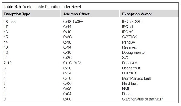
In the ARM Cortex M3 core, when an exception occurs, the corresponding handler is called for it. To determine the starting address of the exception handler, a vector table mechanism is used. The vector table is an array of data words within system memory, each of which is the starting address of one type of exception. The table is moved and the movement is controlled by a special VTOR register in SCB (System Control Block) (In the manual, it sounds cooler, but I broke down: The vector table is relocatable, and the relocation is controlled by the NVIC ). After RESET, the value of this register is 0, that is, the vector table lies at the address 0x0 (for the STM32F103 in the startup file, we independently move it to 0x08000000). And what is very important for us, the order is as follows:
- The value lying at 0x04 is the place in the program where we get after the reset- exception
- The value at 0x00 is the initial value of the Main Stack Pointer for the user application.
All this together, plus a bit of magic with a pointer to the function, and Alice jumps after the rabbit.
Now check if it works at all. Let's write a simple LED blinking program with cycles in main () and a couple of interrupts (SysTick and TIM4):
Test programm for MSD bootloader
#include "stm32f10x.h" #include "stm32f10x_gpio.h" #include "stm32f10x_rcc.h" #include "stm32f10x_tim.h" #include "misc.h" #define SYSCLK_FREQ 72000000 #define TICK_1_KHz ((SYSCLK_FREQ / 1000) - 1) #define TICK_1_MHz ((SYSCLK_FREQ / 1000000) - 1) volatile u32 i, j; int main(void) { GPIO_InitTypeDef GPIO_Options; NVIC_InitTypeDef NVIC_Options; RCC_APB2PeriphClockCmd(RCC_APB2Periph_GPIOA | RCC_APB2Periph_GPIOB, ENABLE); RCC_APB1PeriphClockCmd(RCC_APB1Periph_TIM4, ENABLE); GPIO_Options.GPIO_Pin = GPIO_Pin_7; GPIO_Options.GPIO_Speed = GPIO_Speed_2MHz; GPIO_Options.GPIO_Mode = GPIO_Mode_Out_PP; GPIO_Init(GPIOA, &GPIO_Options); GPIO_Options.GPIO_Pin = GPIO_Pin_0 | GPIO_Pin_1; GPIO_Options.GPIO_Speed = GPIO_Speed_2MHz; GPIO_Options.GPIO_Mode = GPIO_Mode_Out_PP; GPIO_Init(GPIOB, &GPIO_Options); GPIOB->BSRR = GPIO_Pin_0 | GPIO_Pin_1; //LEDs off GPIOA->BSRR = GPIO_Pin_7 TIM4->PSC = 720 - 1; //clock prescaller TIM4->ARR = 60000 - 1; //auto-reload value TIM4->CR1 |= TIM_CounterMode_Up;//upcounter TIM4->DIER |= TIM_IT_Update; //update interrupt enable TIM4->CR1 |= TIM_CR1_CEN; //timer start NVIC_Options.NVIC_IRQChannel = TIM4_IRQn; NVIC_Options.NVIC_IRQChannelPreemptionPriority = 0; NVIC_Options.NVIC_IRQChannelSubPriority = 0; NVIC_Options.NVIC_IRQChannelCmd = ENABLE; NVIC_Init(&NVIC_Options); SysTick_Config(TICK_1_KHz); while(1) { __disable_irq(); GPIOB->BSRR = GPIO_Pin_0 | GPIO_Pin_1; //Off for(i = 0; i < 10; i++) { for(j = 0; j < 500000; j++); //Pause GPIOA->ODR ^= GPIO_Pin_7; //Reverse } GPIOA->BSRR = GPIO_Pin_7; //Off __enable_irq(); for(i = 0; i < 5000000; i++); //Pause } } void SysTick_Handler(void) { volatile static u32 LED_Counter = 0; if(LED_Counter >= 40) { GPIOB->ODR ^= GPIO_Pin_1; //Reverse LED_Counter = 0; } LED_Counter++; } void TIM4_IRQHandler() { TIM4->SR = ~TIM_SR_UIF; GPIOB->ODR ^= GPIO_Pin_0; //Reverse } By the way, you need to remember to fix a couple of things in the project, without which nothing will work:
- Remove from SystemInit () the operation of moving the vector table by some value ( // SCB-> VTOR = FLASH_BASE ). Bootloader moves it yourself before moving to the user program!
- In the Linker script, change the beginning of our program from the address 0x08000000 to the address of the beginning USER_MEM ( FLASH (rx): ORIGIN = 0x08010000, LENGTH = 200K );
And this is how this code is executed (well, maybe not everyone has seen the LEDs blink ...):
And this is how the download log of this firmware in the MK via the bootloader looks like:
UART log message
--------------- START LOG ---------------
BOOT_MEM start addr: 0x08000000
BOOT_MEM size: 64K
USER_MEM start addr: 0x08010000
USER_MEM size: 200K
MSD_MEM start addr: 0x08042000
MSD_MEM size: 200K
OTHER_MEM start addr: 0x08074000
OTHER_MEM size: 48K
Total memory size: 512K
BOOTLOADER Mode ...
FAT FS mount status = 0
Application file open status = 0
Difference between MSD_MEM and USER_MEM: 4 byte from 2212 byte
Start copy MSD_MEM to USER_MEM:
File size = 2212 byte
Body size = 2048 byte
Tail size = 164 byte
Sector 0 (0x08010000 - 0x08010800) erased
Sector 1 (0x08010800 - 0x08011000) erased
0 cycle, read status = 0, 512 byte read
512 byte programmed: 0x08010000 - 0x08010200
1 cycle, read status = 0, 512 byte read
512 byte programmed: 0x08010200 - 0x08010400
2 cycle, read status = 0, 512 byte read
512 byte programmed: 0x08010400 - 0x08010600
3 cycle, read status = 0, 512 byte read
512 byte programmed: 0x08010600 - 0x08010800
Tail read: read status = 0, 164 byte read, size of tail = 164
New size of tail = 164
164 byte programmed: 0x08010800 - 0x080108A4
File close status = 0
FAT FS unmount status = 0
DeInit peripheral and jump to 0x08010561 ...
Let's sum up. The bootloader turned out! And even works. With the output of debug messages in the UART, it occupies 31,684 bytes of FLASH memory, without - 25,608 bytes. Not so little, if you also consider how much memory you need to give for Mass Storage disk. Sources and working draft (Atollic TrueSTUDIO) can be viewed on Bitbucket .
Thanks for attention!
Source: https://habr.com/ru/post/309218/
All Articles