On the process of creating a server - from idea to detail
Hello! My name is Alexey, I lead the creation of equipment in the company YADRO - I coordinate the work of everyone who is somehow involved in the development process.
At the end of the last article Maxim maxf75 slightly touched the features of the location of memory slots. Today I will tell you in general about how we came to the version of architecture and layout that we are working on now.
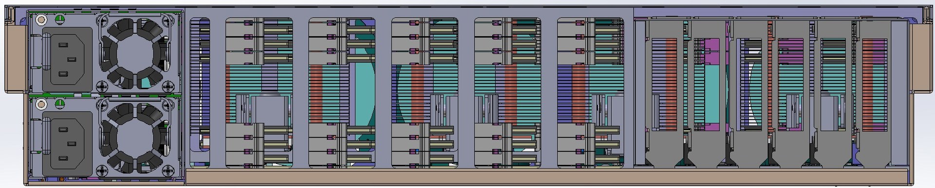
Rear view of the designed server with the rear grille removed.
')
When designing, we proceeded from the key requirement: to ensure the maximum amount of memory. In general, this is the topic of a separate article, how the company took up the development on the basis of OpenPOWER, defined the target tasks for the server and came to this requirement. Between the rest of the publications we will tell this story. In the meantime, let's take as a starting point for the design: a server based on OpenPOWER with the maximum amount of memory.
It should be noted that the solutions that are available on the market now and which allow us to provide a really large amount of memory have one major drawback - the server cost is several times higher than the cost of the memory installed in it. That is why we decided to create a server that will break this tradition and allow us to provide up to 8 TB of memory in one machine while maintaining the total cost (as far as possible generally considering the cost of 8 TB DDR4 itself) of the cost of the solution.
Together with the goal of maximizing the amount of memory, the desire to provide a high density immediately arose - sometimes this turns out to be an important factor determining a competitive advantage when compared with other servers. After a couple of weeks of thinking and estimating pieces of paper, I had the feeling that we could put all this in a standard 19 ”chassis with a height of 2U.
Given the target amount of memory and the total number of strips, its location is a determining factor when building a server layout. It is clear that it is simply impossible to place 128 DIMM modules on the motherboard both on the basis of banal geometry (the board will be gigantic in size), and on the basis of Signal Integrity requirements. Obviously, to load up our amount of memory, you need to make risers vertically placed in the chassis that are connected to the motherboard. On the risers, you must place the connectors for the DIMMs and the Centaur memory buffer, which contains the cache and provides processor access to the memory (one processor supports up to 4 memory buffers).
The first idea of arranging the riser meant placing the modules on one side, and the memory buffers on the side next to them, as in the picture. But, first, we came up against the restriction on the length of the tracks from the buffer to the DIMMs, and secondly, we realized that there would be problems with their alignment.

Initial layout of the memory riser layout
I had to do it differently - to place the memory buffer chip between two groups of DIMMs. At first, it was a little unclear whether such a decision would pass in height, but carefully considering the height of the riser, we realized that when placing components with minimum tolerances, the resulting board passes between the bottom and the lid of the 2U case. Thus, the connector for connecting to the motherboard had to be moved sideways, and the riser was:

The board is complex, 18 layers.
Then we started building the overall layout of the server. Traditionally, in front of the chassis are the disks for local storage. For a 2U chassis, the most standard options are either 24 × 2.5 ”or 12 × 3.5”. We chose the first one - 3.5 ”drives are not very interested in this project, since we focus more on SSD.
Fans are classically placed behind the discs - there were no special questions here either: 5 fans of the popular size 80 × 38 mm were installed - actually, the maximum that fit the width. Here, too, there were tasks with which we had to tinker - when placing five fans, there is almost no space left for the connectors (it is necessary to ensure that they can be replaced on the go). Unscrew by finding very compact connectors and placing them virtually in the volume occupied by the fans themselves.
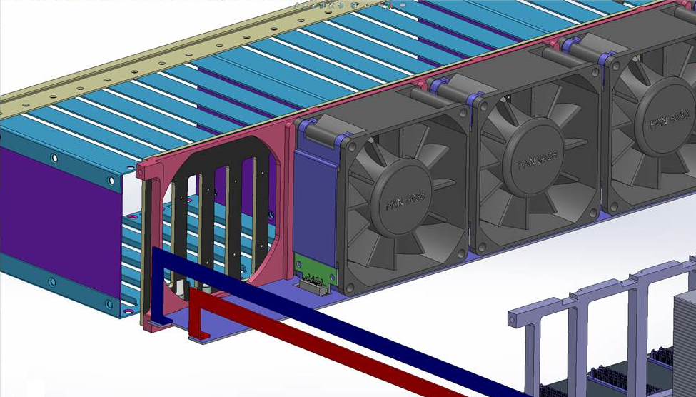
Connecting fans. For convenience of display, the middle fan and the near guide frame are hidden.
Fans are connected to the card underneath, which draws power and speed control lines. Each fan has its own control channel. The picture shows the power bus leading to the board - they run along the left side of the server, if you deploy it to the power supply unit. A loop runs along the right side to transmit PWM control signals from the motherboard.
Connecting local drives is also not that easy. We really like the NVMe standard, and we generally think that the future lies with it. Whatever new types of memory appear in the foreseeable period (the same 3D-XPoint from the Intel and Micron alliance), they will most likely be used in the NVMe version of the disks, since PCI Express is the shortest way to connect anything to the processor today (yes, we know about NV-DIMM, but this is a very expensive compromise, which also eats away valuable memory slots for us). On the other hand, we would not want to completely and completely reject support for SAS / SATA. These considerations in a rather logical way led us to the decision that we will place connectors on the motherboard, which allow us to bring the PCI Express bus to the disk controllers, be it a PCI Express switch or a SAS HBA / RAID controller.
Molex’s NanoPitch solution was chosen as the most suitable connector-cable pair for us (in fact, it’s just an implementation of the actively promoted OCuLink PCI SIG). Cables for internal connections are quite compact and allow you to push up to 8 PCIe Gen3 lanes through a single cable.
Then the question arose about where to actually place the disk controllers. On the backplane, to which the disks are connected, it is simply impossible to do this (chips that SAS controllers, that PCIe switches are too big for this). After a careful study of the sizes of the disks, the maximum permissible chassis height and the elaboration of various options for the design of disk trays, it became clear that, in general, it is possible to place a board with controllers above the disks. Such an arrangement, firstly, simplifies its connection to the disk backplane (standard CardEdge connectors can be used), and secondly, it reduces the height of the disk trays by eliminating the optical fibers and placing the entire display on the controller board.
The result was the following connection scheme:
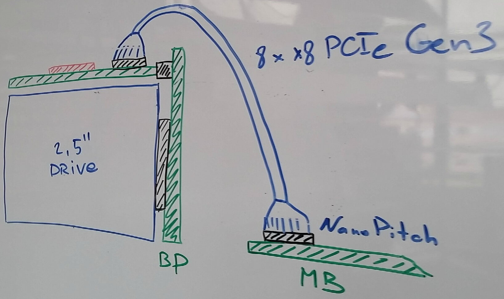
For a change - art by hand. Wiring diagram drives. Magnetic board, markers, 2016.
The board with a PCIe switch or SAS controller is located above the disks and is connected to the motherboard with a cable. The board itself is connected to the disk backplane in which the drives are inserted.
Power supplies are usually placed in the left or right rear corner of the case. It was more convenient for us, based on the design of the PDB (Power Distribution Board), to arrange them in the left (as seen from the back). The power supplies decided to use the CRPS standard, the main advantages of which are the high power density of the power supplies (2 kW today, up to 2.4 - almost tomorrow), high efficiency, and most importantly - this is not some proprietary standard of a single vendor, but a standard , initiated by Intel at the time, and which was supported by a significant number of companies. Two two-kilowatt power supply in our case are located one above the other.
Since we place one memory buffer and 8 DIMMs (the maximum amount supported by Centaur) at each riser, it turns out that we need four raisers per processor, that is, only 16 of them in the chassis. Based on the height of standard DDR4 RDIMM modules, the width of such risers in the chassis can accommodate no more than 11 (and even then, you have to use Ultra-low seating DIMM sockets and shrink, counting in tenths of millimeters). Therefore, another 5 risers had to be put in another place, on the back of the motherboard. Actually, this resulted in the unfolding of a single processor by 180 degrees (the last Cthulhu picture in the last article ). Considering the height of our memory risers from the bottom to the server lid, another cutout was added to the limitations of the shape of the motherboard.
After that, it remains only to place the slots for standard PCI Express cards, the number of which was clearly determined by the free space. It turned out to accommodate 5 slots, plus a separate connector for the management board (to unload the motherboard, we decided to put it on a separate BMC card, USB and Ethernet - all this was placed on a separate small board, which is installed in the same sixth slot).
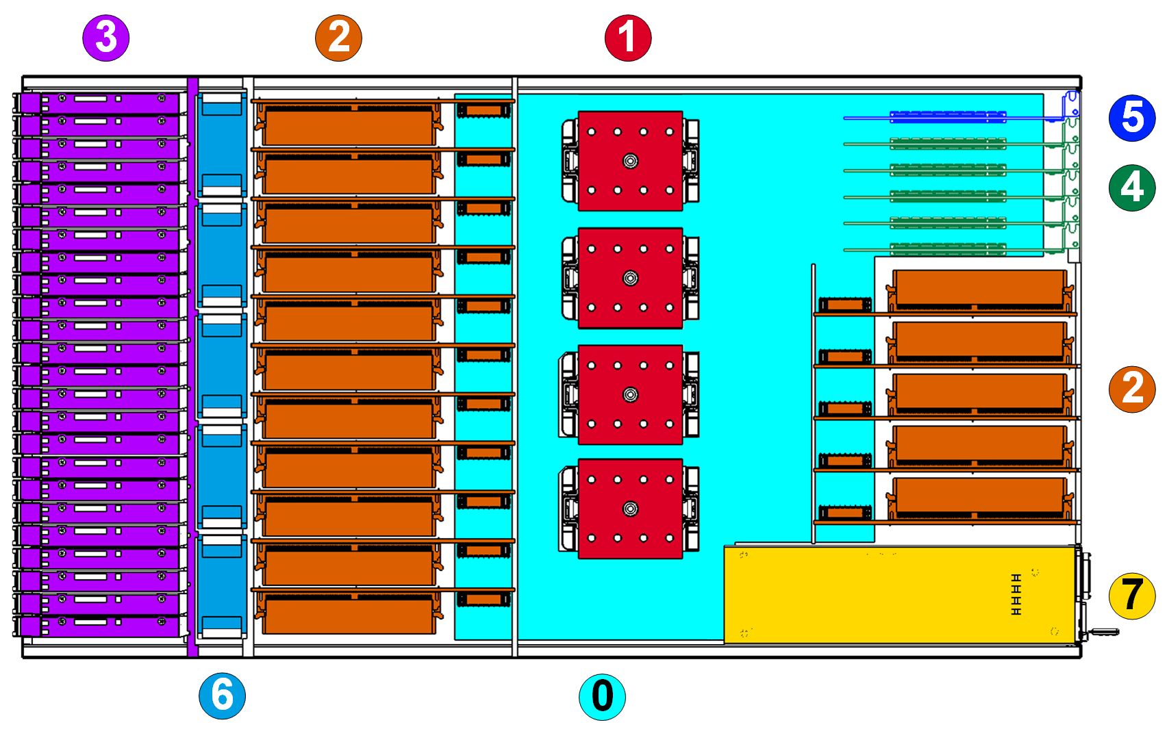
The result was a picture of the location of the components (top view, the board with the controllers above the disks is not shown so that the disks do not obscure):
Legend:
These are the considerations that I described and determined the look of the server. Total: standard 19 ”chassis 2U high, 4 sockets for POWER8 processors, 16 connectors for risers with memory bars (up to 128 DIMM modules in the entire server, 8 for each riser), 5 standard PCI Express slots for expansion cards and one card management.
At the end of the last article Maxim maxf75 slightly touched the features of the location of memory slots. Today I will tell you in general about how we came to the version of architecture and layout that we are working on now.
Rear view of the designed server with the rear grille removed.
')
When designing, we proceeded from the key requirement: to ensure the maximum amount of memory. In general, this is the topic of a separate article, how the company took up the development on the basis of OpenPOWER, defined the target tasks for the server and came to this requirement. Between the rest of the publications we will tell this story. In the meantime, let's take as a starting point for the design: a server based on OpenPOWER with the maximum amount of memory.
It should be noted that the solutions that are available on the market now and which allow us to provide a really large amount of memory have one major drawback - the server cost is several times higher than the cost of the memory installed in it. That is why we decided to create a server that will break this tradition and allow us to provide up to 8 TB of memory in one machine while maintaining the total cost (as far as possible generally considering the cost of 8 TB DDR4 itself) of the cost of the solution.
Together with the goal of maximizing the amount of memory, the desire to provide a high density immediately arose - sometimes this turns out to be an important factor determining a competitive advantage when compared with other servers. After a couple of weeks of thinking and estimating pieces of paper, I had the feeling that we could put all this in a standard 19 ”chassis with a height of 2U.
Memory
Given the target amount of memory and the total number of strips, its location is a determining factor when building a server layout. It is clear that it is simply impossible to place 128 DIMM modules on the motherboard both on the basis of banal geometry (the board will be gigantic in size), and on the basis of Signal Integrity requirements. Obviously, to load up our amount of memory, you need to make risers vertically placed in the chassis that are connected to the motherboard. On the risers, you must place the connectors for the DIMMs and the Centaur memory buffer, which contains the cache and provides processor access to the memory (one processor supports up to 4 memory buffers).
The first idea of arranging the riser meant placing the modules on one side, and the memory buffers on the side next to them, as in the picture. But, first, we came up against the restriction on the length of the tracks from the buffer to the DIMMs, and secondly, we realized that there would be problems with their alignment.
Initial layout of the memory riser layout
I had to do it differently - to place the memory buffer chip between two groups of DIMMs. At first, it was a little unclear whether such a decision would pass in height, but carefully considering the height of the riser, we realized that when placing components with minimum tolerances, the resulting board passes between the bottom and the lid of the 2U case. Thus, the connector for connecting to the motherboard had to be moved sideways, and the riser was:
The board is complex, 18 layers.
Local storage and cooling fans
Then we started building the overall layout of the server. Traditionally, in front of the chassis are the disks for local storage. For a 2U chassis, the most standard options are either 24 × 2.5 ”or 12 × 3.5”. We chose the first one - 3.5 ”drives are not very interested in this project, since we focus more on SSD.
Fans are classically placed behind the discs - there were no special questions here either: 5 fans of the popular size 80 × 38 mm were installed - actually, the maximum that fit the width. Here, too, there were tasks with which we had to tinker - when placing five fans, there is almost no space left for the connectors (it is necessary to ensure that they can be replaced on the go). Unscrew by finding very compact connectors and placing them virtually in the volume occupied by the fans themselves.
Connecting fans. For convenience of display, the middle fan and the near guide frame are hidden.
Fans are connected to the card underneath, which draws power and speed control lines. Each fan has its own control channel. The picture shows the power bus leading to the board - they run along the left side of the server, if you deploy it to the power supply unit. A loop runs along the right side to transmit PWM control signals from the motherboard.
Connecting local drives is also not that easy. We really like the NVMe standard, and we generally think that the future lies with it. Whatever new types of memory appear in the foreseeable period (the same 3D-XPoint from the Intel and Micron alliance), they will most likely be used in the NVMe version of the disks, since PCI Express is the shortest way to connect anything to the processor today (yes, we know about NV-DIMM, but this is a very expensive compromise, which also eats away valuable memory slots for us). On the other hand, we would not want to completely and completely reject support for SAS / SATA. These considerations in a rather logical way led us to the decision that we will place connectors on the motherboard, which allow us to bring the PCI Express bus to the disk controllers, be it a PCI Express switch or a SAS HBA / RAID controller.
Molex’s NanoPitch solution was chosen as the most suitable connector-cable pair for us (in fact, it’s just an implementation of the actively promoted OCuLink PCI SIG). Cables for internal connections are quite compact and allow you to push up to 8 PCIe Gen3 lanes through a single cable.
Then the question arose about where to actually place the disk controllers. On the backplane, to which the disks are connected, it is simply impossible to do this (chips that SAS controllers, that PCIe switches are too big for this). After a careful study of the sizes of the disks, the maximum permissible chassis height and the elaboration of various options for the design of disk trays, it became clear that, in general, it is possible to place a board with controllers above the disks. Such an arrangement, firstly, simplifies its connection to the disk backplane (standard CardEdge connectors can be used), and secondly, it reduces the height of the disk trays by eliminating the optical fibers and placing the entire display on the controller board.
The result was the following connection scheme:
For a change - art by hand. Wiring diagram drives. Magnetic board, markers, 2016.
The board with a PCIe switch or SAS controller is located above the disks and is connected to the motherboard with a cable. The board itself is connected to the disk backplane in which the drives are inserted.
Power supplies
Power supplies are usually placed in the left or right rear corner of the case. It was more convenient for us, based on the design of the PDB (Power Distribution Board), to arrange them in the left (as seen from the back). The power supplies decided to use the CRPS standard, the main advantages of which are the high power density of the power supplies (2 kW today, up to 2.4 - almost tomorrow), high efficiency, and most importantly - this is not some proprietary standard of a single vendor, but a standard , initiated by Intel at the time, and which was supported by a significant number of companies. Two two-kilowatt power supply in our case are located one above the other.
A little more about memory
Since we place one memory buffer and 8 DIMMs (the maximum amount supported by Centaur) at each riser, it turns out that we need four raisers per processor, that is, only 16 of them in the chassis. Based on the height of standard DDR4 RDIMM modules, the width of such risers in the chassis can accommodate no more than 11 (and even then, you have to use Ultra-low seating DIMM sockets and shrink, counting in tenths of millimeters). Therefore, another 5 risers had to be put in another place, on the back of the motherboard. Actually, this resulted in the unfolding of a single processor by 180 degrees (the last Cthulhu picture in the last article ). Considering the height of our memory risers from the bottom to the server lid, another cutout was added to the limitations of the shape of the motherboard.
After that, it remains only to place the slots for standard PCI Express cards, the number of which was clearly determined by the free space. It turned out to accommodate 5 slots, plus a separate connector for the management board (to unload the motherboard, we decided to put it on a separate BMC card, USB and Ethernet - all this was placed on a separate small board, which is installed in the same sixth slot).
General scheme
The result was a picture of the location of the components (top view, the board with the controllers above the disks is not shown so that the disks do not obscure):
Legend:
0. System board.
1. IBM POWER8 SCM Turismo processors.
2. Memory raisers with DIMMs.
3. 24 × 2.5 ”disk and disk backplane
4. Expansion card slots (only HHHL, that is, low profile cards are supported).
5. Management fee.
6. Cooling fans.
7. Power supplies.
These are the considerations that I described and determined the look of the server. Total: standard 19 ”chassis 2U high, 4 sockets for POWER8 processors, 16 connectors for risers with memory bars (up to 128 DIMM modules in the entire server, 8 for each riser), 5 standard PCI Express slots for expansion cards and one card management.
Source: https://habr.com/ru/post/309080/
All Articles