Model of the interaction of ships with water in video games: part 2
Welcome to the second part of the series of articles on the physics of ships in video games. In the first part, I explained the principles of pushing out and justified the choice of calculating the hydrostatic forces acting on the vessel. I also indicated that we are laying an important foundation for calculating not only hydrostatic forces, but also for hydrodynamic forces in our simplified model. I mean, we will calculate the additional forces for each immersed triangle, summarize them and apply them to the vessel. Everything really will be so simple.
Or so it may seem at first glance. It turned out that modeling the remaining forces to give the ship an acceptable dynamic response required much more research and iteration than laying the entire foundation in Part 1 and calculating the pushing. In retrospect, the first part can be compared with a walk in the park. The second part looks more like a cross-country run in the jungle, full of pit-traps with stakes, when hungry wolves (that is, producers) chase you.
If you have not read the first part, here is a brief conclusion. The ship is modeled as a triangulated mesh. We approximate the surface of the water with a height field and, using a fast algorithm for intersecting an approximated triangle with a height field, determine the part of the vessel that is under water as a list of immersed triangles. Each triangle of the original mesh can create 0, 1, or 2 fully submerged triangles. The algorithm in action is shown in Figure 1.
')

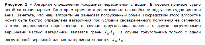
Figure 2 shows the typical distribution of hydrostatic pressure on the submerged part of the vessel. As a rough approximation, we have assumed that the pressure is constant over the entire surface of a submerged triangle. The movement of the vessel shown here is not the result of hydrostatic forces only.
Figure 2 - Distribution of hydrostatic pressure obtained in our model. It should be noted that this behavior is obtained for the full model, and not by applying to the vessel only hydrostatic forces. The ship falls from a height of 2 meters and slows down for a while. Then it teleports to 2 meters under water, pushed to the surface and also slows down for a while. The pressure is considered constant for the entire immersed triangle, and can be quite large. The larger the body triangles, the rougher the approximation. However, the model works and is stable even with fairly low poly meshes.
As can be seen from Figure 3, the application of hydrostatic forces alone is not enough to accurately simulate the behavior of the body in water. In my opinion, this is a great feature of programming and simulation. It gives us the opportunity to check whether the given model is close enough to real physical behavior. While we are hopelessly slowly approaching the creation of good models for physical phenomena, especially in accordance with exact mathematical conditions, our eyes and the brain are able to quickly and with high accuracy recognize a simulation that is not similar to the actual behavior of objects. In our case, the simulation shows us how important the resistance forces are for the ship, and what would have happened if they had not existed in some very strange elastic parallel universe.
Figure 3 - Dynamic reaction of the vessel, to which only hydrostatic forces are applied, on a completely flat surface of the water. It will be quite difficult to fish from such a boat. Obviously, resistance forces play a big role in the real world.
It appears that in Figure 3 the boat is attached to a spring, and not on the water. From our experience, we know that a vessel dropped into the water from a height will rather quickly stop oscillating up and down. This is called attenuation, slowing down, caused by opposing forces. As a result, the maximum height achieved when moving up and down becomes smaller and smaller. In the case of critical attenuation, the forces are large enough to immediately stop the oscillations.
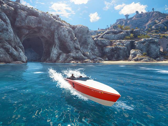
Fun with a Just Cause 3 patrol boat. Water simulation is performed by NVIDIA WaveWorks.
Model stabilization
When I decided to create a simple model of forces acting on a ship, I had a rather vague plan for what I wanted to accomplish. It was something between “developing a stable model of a boat that realistically responds to big waves and which is interesting to manage” and “hmm, how difficult will it be?”. Having determined the forces that need to be applied to the vessel, we must stabilize them so that it does not jump uncontrollably through the water. In addition, if we introduce too large or unstable forces, we need protection so that the ship does not reach insane speeds. Therefore, the first thing we did was add large damping forces for both linear and angular components in order to stabilize the oscillations that I was talking about. Attenuation is simply proportional to how much the body is immersed in water. As you can remember, each frame we define a list of immersed triangles, so the simplest calculation of the submerged part of the vessel is determined by the ratio between the immersed area and the total area of the vessel.

For example, we can introduce a linear damping force that looks like this:

or quadratic attenuation:


Before diving: spoiler
In the end, we use 3 different forces resulting from the interaction of the vessel and water: the viscosity of the water, the pressure resistance and the impact force of the hull (or the force entering the water). Each of these forces was added to the model, because it somehow correlates with reality, and also because it relates to a specific problem. In the rest of the article, I will explain what physical realities these forces should represent, and also tell you what motivated me to add these forces, i.e. What range of problems does each force belong to? Do not forget that this is a simplified model, so some of the forces are rather indirectly related to physical reality. This applies in particular to pressure resistance, which is a huge simplification of what is connected with wave resistance and splash resistance in a more complex hydrodynamic theory. The fourth force, the added mass force, did not take root in the final model, but I am still thinking about how to take it into account in calculations for a better sense of inertia.
Resistance equation
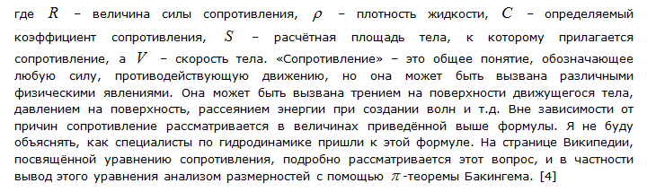
Since below we will talk a lot about resistance, I want to stop for a second and consider the equation of resistance. If it is familiar to you, you can proceed to the next section. Fluid dynamics resistance
traditionally expressed in the following form:


Components of a triangle
Before starting the description of our model of hydrodynamic forces, I will enter the values and vectors associated with the submerged triangles of the ship's hull. All forces are calculated with their help.
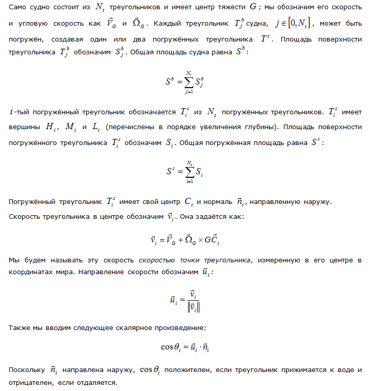
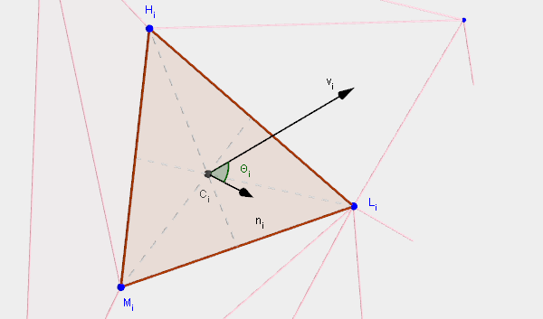
Figure 5 - Some useful values for each immersed triangle.
Viscous fluid resistance
I will start with the resistance of a viscous fluid, as many texts on hydrodynamics begin. Viscosity Resistance
occurs when water flows along the surface. Since there is a strong interaction between the water directly next to the hull and the surface of the hull, there is a microscopic layer of water that practically “sticks” to the surface and moves along with the vessel. With increasing distance from the body, the water “sticks” less and less. To simplify the picture a little, each microscopic layer of water at a given distance from the surface interacts with one layer directly in front of it and with one layer immediately after it. The intensity of this interaction is called viscosity. The more viscous the liquid, the more the liquid sticks to the surface and stretches behind it. (*) It creates a force called the resistance of a viscous fluid.
Many experiments have been carried out to measure the resistance of a viscous fluid, and there are good empirical formulas for predicting the resistance of a viscous fluid created by a ship. For example, let's take a smooth flat plate that moves under the surface of the water. If the plate is thin and moves along its length so that it does not collide with the flow, then the measured force is almost entirely due to the resistance of the viscous fluid. In many countries, special installations have been created, called experimental pools, to measure, among other things, the hydrodynamic forces acting on immersed bodies moved in water. Some countries discuss the findings at the International Experimental Basin Conference (ITTC), which has been held every 3 years since 1933 (only once was a 9 year pass due to World War II). In 1957, the ITTC came to the agreement that the formula:

represents a very good approximation of the data. This formula is called the ship model correlation formula and is derived not analytically from the basic principles, but rather is a regression function, which for practical purposes is close enough to the data obtained. Strictly speaking, for us it is not very important, we just need some formula that we can apply to each of our triangles to calculate the viscous friction. But this shows us that the physics of fluid dynamics is so complex that in practice they are limited to measurable resistance, and do not use analytical formulas.
Fluid viscosity is not the only parameter affecting the magnitude of the force. First, the surface roughness is also important. A rougher surface will interact more with a thicker layer of water than a smoother one. Even more important is the flow turbulence near the surface. Before the vessel, the flow is considered laminar. It is ordered and the layers at an increasing distance from the surface flow parallel to each other, even if at different speeds, since they affect the speeds of each other at the microscopic level due to viscosity (**). But the longer the fluid flows along the surface, the more turbulent it becomes, and the more layers it mixes with each other. When the various layers of the turbulent mix, the amount of accelerated surface of the liquid increases, which leads to an increase in resistance. So we should expect greater resistance to a viscous fluid near the stern of the vessel compared to the bow. And finally, the three-dimensional shape of the vessel is important. It differs from the flat plate and changes the nature of the flow. Since the ship is not completely flat, liquids need to go a longer distance and the relative velocity of the fluid is usually higher than the speed of the ship. Due to the non-planar shape of the boat, the pressure along the surface varies, and this also affects the resistance.

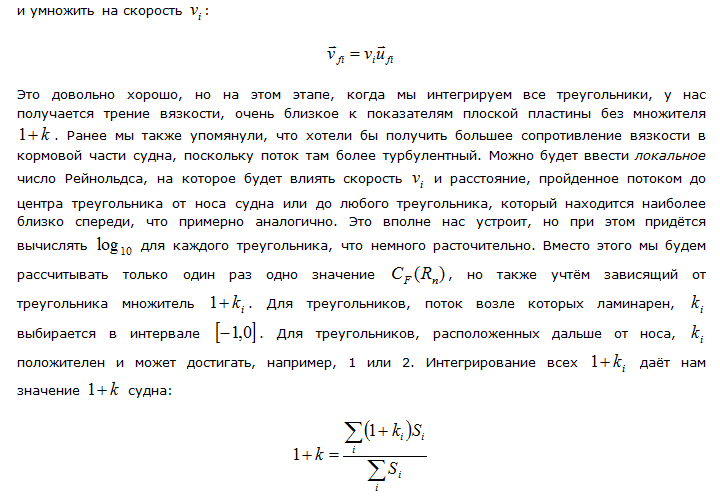
When a ship moves in calm water, the resistance of a viscous fluid is the only force acting on a ship. It is possible that the vessel is sufficiently protruding from the water and the movement is opposed by a relatively small surface, but at the same time most of the bottom touches the water. In this case, the pressure resistance, which we consider below, will be quite small, but we still need high water resistance. In addition, if we make a ship two or three times longer without changing the frontal surface, we need to increase the resistance, and we will achieve this using viscosity resistance, since it occurs mainly on hull triangles that are tangential to speed.

Figure 6 - The dynamic behavior of the vessel, subject to the pushing force only viscosity resistance. Despite the fact that very good empirical formulas for the resistance of a viscous fluid are used, which are quite convenient to use, they do not lead to any attenuation of the vessel's motion at all. In this case, the vessel is dropped from a height of one meter from the surface of the water. The resistance of a viscous fluid plays an important role, but it is significant only at high speeds.
Pressure resistance forces
Now we come to the second force: the force of pressure resistance. Also here we will move away from serious physics, and I will explain why.
In marine hydrodynamics, scientists share the resistance of the wave profile, the resistance of wave destruction, the additional resistance during the course of rough seas, splash resistance, eddy-forming forces, etc. They do not always correspond to a particular physical property. Rather, these are simply ways of taking into account in hydrodynamics the fact that there is total resistance to a vessel moving in water. exceeds the viscosity resistance. Observing the vessel and its surrounding water, it can be understood that energy is dissipated not only due to the resistance of viscosity. For example, the resistance of a wave profile can be assessed by observing the waves created by the ship and determining the resistance value applied to the resistance ship using the Newtonian principle of action and reaction. But most of the time, the slopes of the waves thus created should be small. This simplifies the calculation and allows you to create a fairly simple formula. However, this assumption is incorrect, therefore the resistance of the wave profile is only a fraction of the resistance. Next to the vessel, the slopes of the waves cannot be considered insignificant, the waves collapse, leading to an increase in resistance. This is called wave breaking resistance. Then, if the appropriate model is chosen to calculate the resistance of the destruction of the waves, it may be necessary to select another resistance: splash resistance, it occurs when the impact on the water is so strong that the water turns into a spray. Of course, all this is excitingly interesting, but too complicated and cannot be applied to our model.
Instead of calculating the various components using their separation and estimation as an alternative, we can solve the Navier-Stokes equation numerically. However, as I do not get tired of repeating, all this lies beyond our needs in terms of performance and complexity of the model.
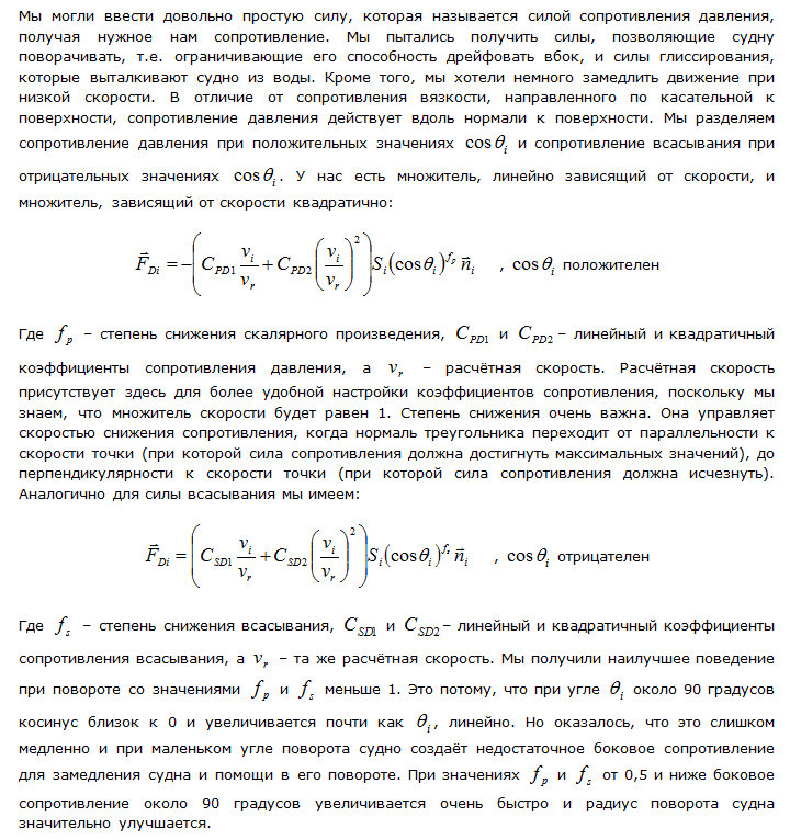
Figure 7 - Dynamic reaction with regard to viscosity resistance and pressure resistance. Fade now works very well. But it is still imperfect. The dynamic reaction is not sufficiently rigid, residual oscillations remain. The attenuation can be increased by choosing a larger value for the pressure drag coefficient, but this will lead to unrealistic vessel maneuverability. For example, a ship will become unrealistic to slow down quickly after moving at a given speed, as if the ship is going through mud and not through water. We need another force that is responsive to a very non-linear or non-quadratic dynamic reaction of a ship interacting with water.
The pressure resistance force is normal to the surface of the vessel. At speed, it serves as a slip force: if a ship has sufficient driving force to overcome a force opposing its acceleration, the hydrodynamic pressure rises in the lower part of the ship, lifting it upwards. When the vessel is lifted, the forces of friction and pressure create less resistance (except for the bottom of the vessel). That is why planing vessels usually have flatter bottoms, so that the horizontal surface, on which they are supported when sliding, does not decrease when lifting, only if they are not entirely lifted from the water.
Body impact force
After the application of the resistance of a viscous fluid and pressure resistance, the behavior of the model of the vessel became similar to the behavior of the vessel. However, the vessel can still penetrate into the water more than is permissible, and the general reaction lacks rigidity. Instead of changing the pressure forces that we wanted to carefully adjust for correct turns and slip forces, we decided to introduce another force that would mainly monitor the stiffness of the fluid's response to sudden accelerations or penetrations that are almost similar to collisions of rigid bodies.
Very hard collisions will be difficult to model using a force depending on the depth of penetration or displacement using a discrete integration scheme. An example of this could be a very rigid spring. Since the force is proportional to the displacement from the rest position, the higher the stiffness coefficient, the harder it is to simulate a spring with a fixed time step. There are well-known ways to solve this problem, but they make integration more difficult. Instead of choosing this path, we can use another opportunity, because it is easy to calculate the force necessary to completely stop the movement of the vessel in one frame. Since it is important that the force be arbitrarily rigid, and the theory associated with the forces of the impact of the hull is very complex, we decided to simplify the problem and start with an absolutely rigid reaction and the necessary return of rigidity to a state of equilibrium. We begin by calculating the force of the collision with water. If it is very large, we can apply a force that completely stops the movement, while the vessel stops, as if it had collided with the ground. On the other hand, if the collision has little power, we can provide full control of the movement to other forces and not apply a force that stops the movement. And between these extremes, we can apply various transition functions (more or less stepwise) to obtain different dynamic results: linear, power, sigmoidal, step functions.
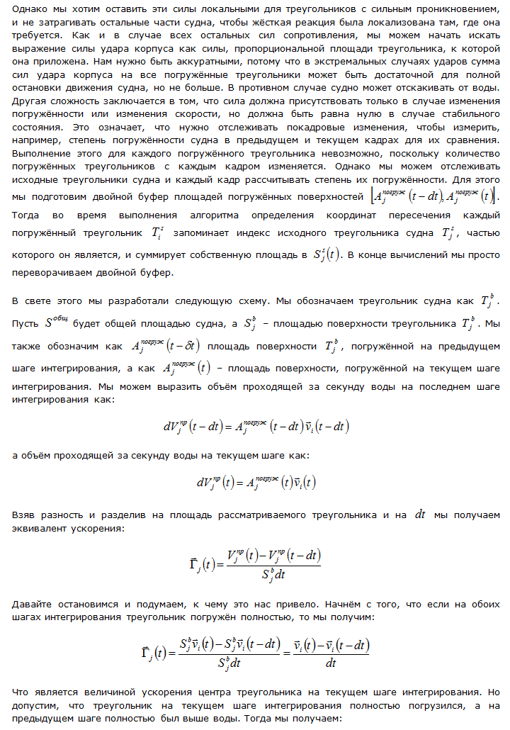
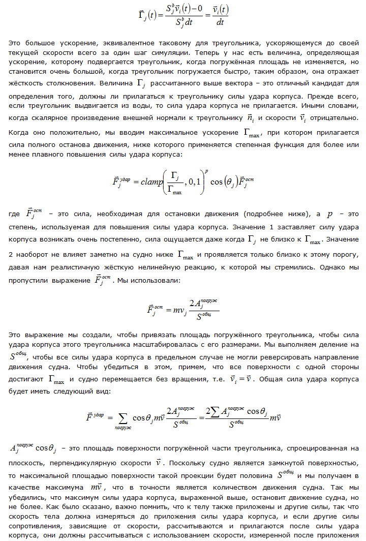
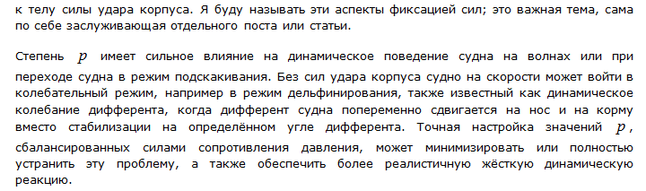
Figure 8 - Dynamic reaction taking into account the impact force of the hull of a vessel falling into the water from a height of 2 m
Figure 9 - Medium wave vessel accelerated to cruising speed when traveling in a straight line. The driving force applied here is very simple, its source is located at the rear and slightly pushes the vessel upwards. Reaction stiffness becomes stronger with increasing speed. There is a jumping effect (delphination), which can be avoided by a combination of more fine-tuning forces, optimizing the shape of the hull, adjusting the driving force depending on the speed, stabilizing the aerodynamic forces. In the lower right corner shows the distribution of pressure resistance forces on the body.
Conclusion
The model of interaction with water developed by us is applicable for a wide range of vessel sizes and shapes, from a two-meter jet ski to a 50-meter corvette (see Figure 10), as well as for larger vessels in conditions from calm to storm and without significant adjustment of variable variable forces. A completely new body with a previously untested form and size can be thrown into the water with some kind of driving force, and immediately begins to show sufficiently correct behavior. Of course, bringing any vessel into a transportable state would require proper positioning and tuning of the engine (or engines), rudders, transom boards and other stabilizing equipment, but a less procedural approach to hydrostatics and hydrodynamics of the hull would take much longer to tune with lower quality results. moreover, they did not so well cope with all possible heights and speeds of the vessel in the water.
The relative simplicity of the model is suitable for our needs. We use Eulerian integration forward, the calculations of the three forces are separated from each other, and they can be separately adjusted; we can easily determine if a given force acts too much or little in a given mode. If we took a longer allowable time for calculations (more than 1 ms), we would expand the current model, but would not choose a more realistic and requiring a large amount of calculations model. However, there is room for improvement in the areas that we will look at below.
One of these areas is the force, called the force of the added mass, or the force of the virtual mass; The Wikipedia quote explains it best: “The meaning of force is that a fluid receives kinetic energy due to the work done by an accelerating submerged body. (...) For ships, the attached mass can easily reach 1/4 or 1/3 of the ship’s mass, and thus represents significant inertia in addition to frictional forces and wave drag forces. ”Virtual mass does not exist as long as the vessel’s speed unchanged. As the ship accelerates, it must dislodge and accelerate a certain proportional part of the fluid in front of it. During deceleration, a certain proportional part of the fluid around the vessel, which received kinetic energy, tends to transfer this energy back to the vessel in the opposite direction to deceleration. It would be undesirable to really change the weight of the vessel in order to realize this effect. Working with a vessel whose mass varies may be very confusing; therefore, it is much preferable to use the power of the virtual mass as well as any other force, so that you can compare them and evaluate its effect on the ability to maneuver the ship, as well as for all other forces. We attempted to realize this power, but did not achieve what we hoped for; perhaps it happened because of lack of time.
Another area in which improvements are possible is the comparison of forces in the existing model with the forces acting on the body, according to realistic computational fluid dynamics simulation (CFD). There are open source packages for calculating CFDs, such as OpenFOAM [6], which already contain ready-made examples for simulating the behavior of a ship's hull in water. One such example is the Wigley hull benchmark. It contains a body, the shape of which is completely mathematically defined and can be used to adjust various coefficients. This makes it easy to compare different simulations with each other or with the given towing tank, since the hulls can be made with a high degree of accuracy. This approach requires the ability to run CFDs for the hull in the detailed configurations of interest and extract information about the forces for comparison. It also requires many hours of calculations on powerful machines to get a few seconds of data. However, this may be a worthwhile contribution to correct those areas where the strengths of the simplified model are most different from the results of CFD calculations.
Also in 1964, Daniel Savicki developed empirical formulas for prismatic gliding enclosures (i.e., for shells that have a well-defined and simple form). « , , , (...) , , .» . [five]
10 — , . — 50 . — , . (- ). , . NVIDIA WaveWorks. [9]
Afterword
, , . , , . . , , , . , , , , . , . , , . , ; : , ? , «» , , ? ? ( ) ? ? , ? , , . 1000, (~100 ) (100 ), (100 ) 90 000 , 900 000. , .
After asking ourselves these questions and answering them, even approximately, we began to move much faster. For example, from [1] and [2] I found out that usually the trim of gliding ships is about 4 degrees, the slip angle during a sharp turn is about 20, and the angle when turning is 25 degrees or more. These values were very useful, because for some reason we tried to avoid too much of a slip angle, which made us underestimate some constants and confused us all the cards at the very beginning.
, , . (Greg Sheel): « : , , ; ». , . , . , , , . , — . , . , , . . , «», cork-screwing, chine walking ( : ) ..
Thanks
Avalanche Studios: (Hamish Young) , , , ; (Roland Lesterlin) , ; (Chris Glover) , , , ; the (Omar Shakir), ( , ); Just Cause 3 . , , 25 . , , «» , , .
Notes
(*) Different fluids have different viscosities. For example, yogurt is very viscous. It seems that the Swedes do not notice this, because they continue to sell yogurt in cartons for milk. I learned this when I first visited Avalanche Studios in Stockholm. In the end, half of the contents stick to the walls of the package when you try to pour it. You have to squeeze the yogurt out of the package like toothpaste. And you already think that avoiding the first time you go shopping for food in tubes was a good idea!
(**) , ( ). , , . , . , ; «» , . , , , . , -.
Links
- Hydrodynamics of High-Speed Marine Vehicles. Odd M. Faltinsen
- Stability of a planing craft in turning motion. Y. Ikeda, H. Okumura and T. Katamaya
- International Towing Tank Conference
- Drag Equation
- Principles of Yacht Design. Lars Larsson, Rolf E. Eliasson and Michal Orych
- Openfoam
- Hydrodynamic Design of Planing Hulls. Marine Technology , D. Savitsky
- Procedures for Hydrodynamic Evaluation of Planing Hulls in Smooth and Rough Water. D. Savitsky, PW Brown
- NVIDIA WaveWorks
Source: https://habr.com/ru/post/309036/
All Articles