Using TCL in FPGA Development
Hello! I have not written an article on my favorite topic for a long time and finally matured for something more or less decent and worthwhile. In this article we will discuss a very interesting task that the development engineer faces almost every day. I suggest you look at how you can use all the power and simplicity of TCL scripts for designing on FPGA . In this article, the description is based on Xilinx FPGA, but this does not negate the capabilities of TCL scripts for FPGA crystals from other manufacturers.

Interesting? Go…
TCL (Tool Command Language) is a high-level scripting language for performing various tasks. Often, TCL is used in conjunction with the Tk graphical shell (Tool Kit) , but this aspect will not be considered in this article. The language is widely used in various tasks of process automation:
Anyway, the main function of the TCL language is the automation of routine tasks , and a significant reduction in the time spent on development. TCL programs do not require build and compilation , which makes the task of debugging scripts simple and straightforward. The TCL interpreter is distributed under a free license and is available for almost all platforms (it is available by default in many Linux distributions). This means that you can use it without any restrictions in the development of private programs and proprietary applications. As of this writing, the current version of TCL is 8.6. There are many distributions available for working with TCL scripts, their debugging and visualization - MyTcl, TclKit, ActiveTcl , etc. The price for 1 ActiveTcl license is about ~ $ 1500, which is unjustified for developing commercial applications. From personal practice, most developers use the familiar command line.
')
All TCL programs consist of commands , which are separated by the symbol ";" or the start of a new line. As in many other programming languages, the first word is a command, the other words are command arguments.
command arg1 argt2 ... argN
For example:
The first command creates the variable NewValue , and the second command prints the value of the variable to the console. To use variables with spaces , quotes are used. In other cases, they are not required. The result of the execution of commands is shown in the figure below:
In my opinion, the main convenience of the TCL language is that any argument of a command can be replaced by another command . To do this, it must be placed in square brackets. In the example below, I will show this opportunity. In addition, TCL is able to control program behavior based on various events. This means that the command handler can perform certain actions not only on the condition recorded in the script, but also on various external events (changing the value of a variable in an external file, capturing data in the channel, ending the execution of the application, reaching the timer counter of a certain value and etc.). The TCL language is rich in a set of commands and contains quite convenient means of working with data arrays and regular expressions. On TCL, the ability to write functions and procedures is implemented, a description of cycles and expressions by condition is available, which makes writing code much easier.
Almost all developers on FPGA / ASIC sooner or later encounter the TCL language in their projects. In modern development of FPGA TCL scripts are actively used for automation and process integration tasks. TCL is included in all leading CAD FPGAs - Quartus for Altera , ISE Design Suite and Vivado for Xilinx . What can TCL do?
etc.
All these stages, one way or another, are the basic operations in the development process on the FPGA: from creating models of node behavior in VHDL / Verilog languages to debugging a finished project in CAD at the stage of synthesis and tracing. As a rule, complex projects contain a large number of modules written by different developers, several IP cores, restriction files, libraries, and function packages. As a result, the finished project has a certain hierarchical structure and a set of rules for connecting certain modules to the required project nodes. It is difficult for a developer to keep in mind the knowledge of where and how the debugged modules should be located and what functions they perform, if they use their work, but knowledge of their work is not required at the design stage (the so-called “ black-box ” modules). TCL script comes to the rescue, which manages the structure of the project and connects the required nodes according to pre-prepared templates. This provides flexibility in development and gives the possibility of repeatability of finished nodes during migration from one project to another.
As a rule, simultaneously with the stage of creating new nodes for the FPGA, the stage of debugging of these nodes proceeds separately from the project and together with the complete system. Primary modeling is carried out abstracted from FPGA on a computer in specialized CAD and modeling environments: these are Modelsim, ISim, Aldec Active-HDL and others. To accomplish the task of debugging projects, TCL scripts also come to the rescue, allowing you to handle events that occur during the simulation, and make decisions on the results of the model. When debugging an RTL node purely in HDL languages, it can be difficult to write a model, since any change in the behavior of the circuit will result in the need to change the model and testing sets. Using a bunch of models in HDL language and TCL scripts is quite convenient and allows you to speed up the debugging process as well as unify complex tests for many solutions.
The stages of writing code and debugging are followed by the usual steps of synthesis, placement and tracing of the project in the FPGA chip. Perhaps this is one of the most difficult steps, which requires large computing resources of the workstation and a long execution time to complete. TCL scripts allow you to manage execution events at each stage, analyze the results of various calculations to achieve the best characteristics of the layout and tracing of the project (the amount of resources occupied, the maximum clock frequencies, acceptable values of timing delays, etc.). In addition, TCL makes it possible to eliminate routine actions for selecting and changing settings, restarting the verification stages, and restarting a specific stage when creating the FPGA firmware file. Such design automation almost completely eliminates the constant presence of a person at these stages.
I hope that, having finished reading these lines, you are already convinced that TCL is a convenient and powerful thing that is extremely necessary to use in your projects. Below I will analyze one of the useful scripts that is used by our team to create a project in the Vivado environment, to add already written source files, various IP cores, XCI restriction files, and much more.
Consider one of the simplest TCL scripts to automatically create a project on a FPGA. The preliminary steps are quite minimal: the local machine requires a directory with the source code of the project , as shown in the figure below.
For convenience, I use independent directories for projects created in the Xilinx ISE Design Suite environment and in Vivado , if the FPGA family allows it ( 7 series: Artix, Kintex, Virtex ). The source files are in the / src directory, the vivado project is in the same directory, and the project for the ISE environment is created in the / ise directory, but the synthesis and layout results are stored in the / implement directory. All this is done for the convenience of project management in general and independent management in different environments. It also makes the hierarchy more visual and saves you from a heap of junk files in the source code. Separately, you should note the / top directory in the source directory, where the top-level file and the necessary restriction files lie (for ISE this is * .ucf file, for Vivado this is * .xdc file).
The project contains mixed IP cores - old ones created in ISE and new ones created in Vivado. The core_k7 directory contains all the cores created in CoreGenerator for ISE. They are not regenerated or updated when used in a Vivado project (the * .vhd file is used for modeling, the * .ngc file is used for synthesis, and the * .xco file is not added to the Vivado project). The / ipcores directory contains new kernels in the * .xci format, created directly in the Vivado environment. It should be noted that a separate subdirectory is required for each core; otherwise, the “ LOCKED ” attribute is set for the IP cores in the project, which makes it impossible to update the cores and regenerate them for synthesis.
Let us proceed to the description of the TCL script:
The first line looks for the location of the TCL script on the local machine (located in the src / tcl directory) and creates a string variable with the full path to the file.
In the second line, an additional variable is created, from which part of the path is cut. Both variables are necessary in order to manually not specify the path to the project and the name of the top-level file in the following variables.
The variable PartDev contains the name of the FPGA crystal. And this is the only variable that changes in the project! All other lines of the script remain UNCHANGABLE in any project.
At the next stage, additional variables are created that determine the location of the source files, create a vivado directory if it is not there, etc. I want to note that I check the presence of the vivado directory on the local machine. If the directory exists, it is deleted and re-created so that there are no conflicts in the new project.
The cd command changes the working directory, and the pwd command shows the location of the working directory.
Everything is primitive and understandable here - variables are created that define the names of all source files in the / src directory. To find files, use the findFiles procedure, which we will return to.
A separate search is made for the component component of the PCI-E node, which is a basic and integral part for all our projects.
At the next stage, all IP cores are searched in the project. And the variable SrcSim recorded the names of the files that are used for modeling. The lappend command in the loop adds other values to the variable, forming an array, which in TCL is called a sheet. At this preparatory part of the script ends and the creation of the project begins.
We create a project, define the top-level file, set the FPGA chip type (in this example, it is Kintex-7 K325T), add the found source files.
Set options for simulation files (exclude from synthesis), set the GLOBAL_INCLUDE parameter for cores used in the PCI-E node (this is a specific feature required for our projects).
At this stage, the search for IP-cores of the project in the XCI format is performed, the need to update the kernel version and the locked parameter, which is affected by the FPGA chip change, are checked. After analyzing the kernels, an update is performed and a report on the successful operation is issued.
The final stage, at which the setup of the synthesis and trace settings is made, is selected from the list of available strategies. Then, the synthesis, placement and tracing are run in turn until the FPGA firmware is fully wired.
As you can see, using the script allows you to save the user from the routine work of creating a project, adding new files, updating IP cores and many other things of the same type. The script is fully automated and requires the installation of a single argument - the type of FPGA crystal. It can be set as a variable in the file, or as an argument that is executed simultaneously with the launch of the TCL script. The figure below shows a screenshot of the project workspace in the Vivado environment, which was launched using a script:
Separately, you should pay attention to the findFiles procedure, with which you can search for all files in a directory. Function arguments: basedir - search directory, pattern - search mask.
The search is performed in several steps: defining the working directory as a file template, creating a list by file name indicating the full path and creating a list-type list array if there are more than one files found. An example of the function findFiles is shown in the figure below. For clarification, written a cycle that displays all the files found. As you can see, the full path to each file is indicated.
The script is run from the command line, or using the Vivado GUI application. In the first case, you need to run Vivado TCL Shell and write a simple command
Note: from the command line, you can start the graphical environment by changing the mode to gui by starting the mode.
In the Vivado environment, the scripts run uncomplicated and simple: Menu -> Tools -> Run TCL Script ...

This completes the familiarity with the TCL language. This is not the end of project automation. In this simple example, I wanted to show how using TCL scripts you can automate FPGA design. TCL is very convenient, easy to understand, and most importantly, open to use. According to personal estimates, the introduction of scripts into the life of developers allows us to reduce the time for the complete creation of a project from the initial to the final stage, and to leave more time for "clean" development (writing code). Below are useful links to get familiar with TCL scripts on FPGA.
Thanks for attention!
Interesting? Go…
What is TCL?
TCL (Tool Command Language) is a high-level scripting language for performing various tasks. Often, TCL is used in conjunction with the Tk graphical shell (Tool Kit) , but this aspect will not be considered in this article. The language is widely used in various tasks of process automation:
- Testing of complex modules, nodes, parts of the code;
- Speed prototyping;
- Creating graphical interfaces for console applications;
- The introduction of applications and tasks.
Anyway, the main function of the TCL language is the automation of routine tasks , and a significant reduction in the time spent on development. TCL programs do not require build and compilation , which makes the task of debugging scripts simple and straightforward. The TCL interpreter is distributed under a free license and is available for almost all platforms (it is available by default in many Linux distributions). This means that you can use it without any restrictions in the development of private programs and proprietary applications. As of this writing, the current version of TCL is 8.6. There are many distributions available for working with TCL scripts, their debugging and visualization - MyTcl, TclKit, ActiveTcl , etc. The price for 1 ActiveTcl license is about ~ $ 1500, which is unjustified for developing commercial applications. From personal practice, most developers use the familiar command line.
')
All TCL programs consist of commands , which are separated by the symbol ";" or the start of a new line. As in many other programming languages, the first word is a command, the other words are command arguments.
command arg1 argt2 ... argN
For example:
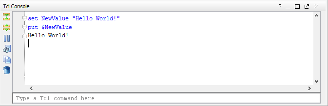
set NewValue “Hello World!” puts $NewValue The first command creates the variable NewValue , and the second command prints the value of the variable to the console. To use variables with spaces , quotes are used. In other cases, they are not required. The result of the execution of commands is shown in the figure below:
In my opinion, the main convenience of the TCL language is that any argument of a command can be replaced by another command . To do this, it must be placed in square brackets. In the example below, I will show this opportunity. In addition, TCL is able to control program behavior based on various events. This means that the command handler can perform certain actions not only on the condition recorded in the script, but also on various external events (changing the value of a variable in an external file, capturing data in the channel, ending the execution of the application, reaching the timer counter of a certain value and etc.). The TCL language is rich in a set of commands and contains quite convenient means of working with data arrays and regular expressions. On TCL, the ability to write functions and procedures is implemented, a description of cycles and expressions by condition is available, which makes writing code much easier.
Why do you need TCL?
Almost all developers on FPGA / ASIC sooner or later encounter the TCL language in their projects. In modern development of FPGA TCL scripts are actively used for automation and process integration tasks. TCL is included in all leading CAD FPGAs - Quartus for Altera , ISE Design Suite and Vivado for Xilinx . What can TCL do?
- creating a project (adding source files, setting options, design hierarchies, assigning a top-level file, etc.),
- synthesis and tracing (up to the creation of independent stages with different settings),
- testing complete nodes, individual modules and the entire project,
- automatic generation of restriction files (UCF / XCI) based on templates,
- checking the time constraints for the synthesized and traced project.
- setting the parameters of the FPGA circuits, components and primitives, setting options for IP cores,
etc.
All these stages, one way or another, are the basic operations in the development process on the FPGA: from creating models of node behavior in VHDL / Verilog languages to debugging a finished project in CAD at the stage of synthesis and tracing. As a rule, complex projects contain a large number of modules written by different developers, several IP cores, restriction files, libraries, and function packages. As a result, the finished project has a certain hierarchical structure and a set of rules for connecting certain modules to the required project nodes. It is difficult for a developer to keep in mind the knowledge of where and how the debugged modules should be located and what functions they perform, if they use their work, but knowledge of their work is not required at the design stage (the so-called “ black-box ” modules). TCL script comes to the rescue, which manages the structure of the project and connects the required nodes according to pre-prepared templates. This provides flexibility in development and gives the possibility of repeatability of finished nodes during migration from one project to another.
As a rule, simultaneously with the stage of creating new nodes for the FPGA, the stage of debugging of these nodes proceeds separately from the project and together with the complete system. Primary modeling is carried out abstracted from FPGA on a computer in specialized CAD and modeling environments: these are Modelsim, ISim, Aldec Active-HDL and others. To accomplish the task of debugging projects, TCL scripts also come to the rescue, allowing you to handle events that occur during the simulation, and make decisions on the results of the model. When debugging an RTL node purely in HDL languages, it can be difficult to write a model, since any change in the behavior of the circuit will result in the need to change the model and testing sets. Using a bunch of models in HDL language and TCL scripts is quite convenient and allows you to speed up the debugging process as well as unify complex tests for many solutions.
The stages of writing code and debugging are followed by the usual steps of synthesis, placement and tracing of the project in the FPGA chip. Perhaps this is one of the most difficult steps, which requires large computing resources of the workstation and a long execution time to complete. TCL scripts allow you to manage execution events at each stage, analyze the results of various calculations to achieve the best characteristics of the layout and tracing of the project (the amount of resources occupied, the maximum clock frequencies, acceptable values of timing delays, etc.). In addition, TCL makes it possible to eliminate routine actions for selecting and changing settings, restarting the verification stages, and restarting a specific stage when creating the FPGA firmware file. Such design automation almost completely eliminates the constant presence of a person at these stages.
I hope that, having finished reading these lines, you are already convinced that TCL is a convenient and powerful thing that is extremely necessary to use in your projects. Below I will analyze one of the useful scripts that is used by our team to create a project in the Vivado environment, to add already written source files, various IP cores, XCI restriction files, and much more.
TCL your FPGA!
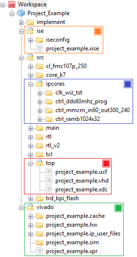
Consider one of the simplest TCL scripts to automatically create a project on a FPGA. The preliminary steps are quite minimal: the local machine requires a directory with the source code of the project , as shown in the figure below.
For convenience, I use independent directories for projects created in the Xilinx ISE Design Suite environment and in Vivado , if the FPGA family allows it ( 7 series: Artix, Kintex, Virtex ). The source files are in the / src directory, the vivado project is in the same directory, and the project for the ISE environment is created in the / ise directory, but the synthesis and layout results are stored in the / implement directory. All this is done for the convenience of project management in general and independent management in different environments. It also makes the hierarchy more visual and saves you from a heap of junk files in the source code. Separately, you should note the / top directory in the source directory, where the top-level file and the necessary restriction files lie (for ISE this is * .ucf file, for Vivado this is * .xdc file).
The project contains mixed IP cores - old ones created in ISE and new ones created in Vivado. The core_k7 directory contains all the cores created in CoreGenerator for ISE. They are not regenerated or updated when used in a Vivado project (the * .vhd file is used for modeling, the * .ngc file is used for synthesis, and the * .xco file is not added to the Vivado project). The / ipcores directory contains new kernels in the * .xci format, created directly in the Vivado environment. It should be noted that a separate subdirectory is required for each core; otherwise, the “ LOCKED ” attribute is set for the IP cores in the project, which makes it impossible to update the cores and regenerate them for synthesis.
Let us proceed to the description of the TCL script:
# Stage 1: Specify project settings set TclPath [file dirname [file normalize [info script]]] set NewLoc [string range $TclPath 0 [string last / $TclPath]-5] set PartDev "xc7k325tffg900-2" set PrjDir [string range $TclPath 0 [string last / $NewLoc]] set TopName [string range $NewLoc [string last / $NewLoc]+1 end] The first line looks for the location of the TCL script on the local machine (located in the src / tcl directory) and creates a string variable with the full path to the file.
In the second line, an additional variable is created, from which part of the path is cut. Both variables are necessary in order to manually not specify the path to the project and the name of the top-level file in the following variables.
The variable PartDev contains the name of the FPGA crystal. And this is the only variable that changes in the project! All other lines of the script remain UNCHANGABLE in any project.
# Stage 2: Auto-complete part for path set PrjName $TopName.xpr set SrcDir $PrjDir/$TopName/src set VivNm "vivado" set VivDir $PrjDir/$TopName/$VivNm cd $PrjDir/$TopName pwd if {[file exists $VivNm] == 1} { file delete -force $VivNm } file mkdir $VivNm cd $VivDir At the next stage, additional variables are created that determine the location of the source files, create a vivado directory if it is not there, etc. I want to note that I check the presence of the vivado directory on the local machine. If the directory exists, it is deleted and re-created so that there are no conflicts in the new project.
The cd command changes the working directory, and the pwd command shows the location of the working directory.
# Stage 3: Find sources: *.vhd, *.ngc *.xci *.xco *.xdc etc. # This stage used instead of: add_files -scan_for_includes $SrcDir set SrcVHD [findFiles $SrcDir "*.vhd"] set SrcVer [findFiles $SrcDir "*.v"] set SrcNGC [findFiles $SrcDir "*.ngc"] set SrcXCI [findFiles $SrcDir "*.xci"] set SrcXDC [findFiles $SrcDir "*.xdc"] set SrcPCI [findFiles $SrcDir "cl_pcie*"] set NewLoc [string range $SrcPCI 0 [string last / $SrcPCI]-6] Everything is primitive and understandable here - variables are created that define the names of all source files in the / src directory. To find files, use the findFiles procedure, which we will return to.
A separate search is made for the component component of the PCI-E node, which is a basic and integral part for all our projects.
# Stage 4: Find all subdirs for IP cores (VHD, XCO, NGC, EDN) set PrjAll {} lappend PrjAll $DirIps $DirAdm $SrcDir/core_v2_ise $SrcDir/core_v4_ise $SrcDir/core_v5_ise $SrcDir/core_v6_ise $SrcDir/core_k7 $SrcDir/TestBench set SrcSim {} for {set i 0} {$i < [llength $PrjAll]} {incr i} { set SrcXXX [findFiles [lindex $PrjAll $i] "*.vhd"] put $SrcXXX foreach SrcAdd $SrcXXX { lappend SrcSim $SrcAdd } } At the next stage, all IP cores are searched in the project. And the variable SrcSim recorded the names of the files that are used for modeling. The lappend command in the loop adds other values to the variable, forming an array, which in TCL is called a sheet. At this preparatory part of the script ends and the creation of the project begins.
# Stage 5: Create project and add source files create_project -force $TopName $VivDir -part $PartDev set_property target_language VHDL [current_project] add_files -norecurse $SrcNGC add_files -norecurse $SrcXCI export_ip_user_files -of_objects [get_files $SrcXCI] -force -quiet add_files $SrcVHD add_files -fileset constrs_1 -norecurse $SrcXDC We create a project, define the top-level file, set the FPGA chip type (in this example, it is Kintex-7 K325T), add the found source files.
# Stage 6: Set properties and update compile order set_property top $TopName [current_fileset] for {set i 0} {$i < [llength $SrcSim]} {incr i} { set_property used_in_synthesis false [get_files [lindex $SrcSim $i]] } set NgcGlb [findFiles $DirIps "*.ngc"] for {set i 0} {$i < [llength $NgcGlb]} {incr i} { set_property IS_GLOBAL_INCLUDE 1 [get_files [lindex $NgcGlb $i]] } set_property IS_GLOBAL_INCLUDE 1 [get_files $SrcPCI] Set options for simulation files (exclude from synthesis), set the GLOBAL_INCLUDE parameter for cores used in the PCI-E node (this is a specific feature required for our projects).
# Stage 7: Upgrade IP Cores (if needed) report_ip_status -name ip_status set IpCores [get_ips] for {set i 0} {$i < [llength $IpCores]} {incr i} { set IpSingle [lindex $IpCores $i] set locked [get_property IS_LOCKED $IpSingle] set upgrade [get_property UPGRADE_VERSIONS $IpSingle] if {$upgrade != "" && $locked} { upgrade_ip $IpSingle } } report_ip_status -name ip_status At this stage, the search for IP-cores of the project in the XCI format is performed, the need to update the kernel version and the locked parameter, which is affected by the FPGA chip change, are checked. After analyzing the kernels, an update is performed and a report on the successful operation is issued.
# Stage 8: Set properties for Synthesis and Implementation (Custom field) set_property strategy Flow_PerfOptimized_high [get_runs synth_1] set_property strategy Performance_ExtraTimingOpt [get_runs impl_1] launch_runs synth_1 wait_on_run synth_1 open_run synth_1 -name synth_1 launch_runs impl_1 -to_step write_bitstream wait_on_run impl_1 The final stage, at which the setup of the synthesis and trace settings is made, is selected from the list of available strategies. Then, the synthesis, placement and tracing are run in turn until the FPGA firmware is fully wired.
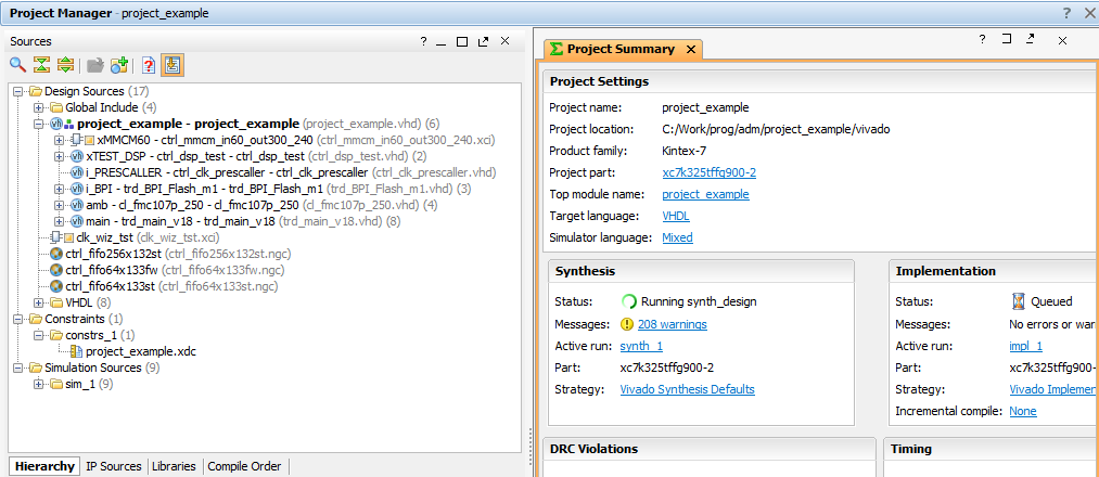
As you can see, using the script allows you to save the user from the routine work of creating a project, adding new files, updating IP cores and many other things of the same type. The script is fully automated and requires the installation of a single argument - the type of FPGA crystal. It can be set as a variable in the file, or as an argument that is executed simultaneously with the launch of the TCL script. The figure below shows a screenshot of the project workspace in the Vivado environment, which was launched using a script:
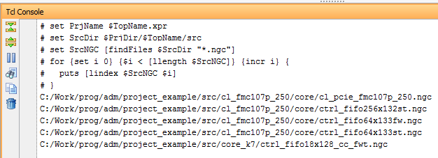
Separately, you should pay attention to the findFiles procedure, with which you can search for all files in a directory. Function arguments: basedir - search directory, pattern - search mask.
proc findFiles { basedir pattern } { set basedir [string trimright [file join [file normalize $basedir] { }]] set fileList {} foreach fileName [glob -nocomplain -type {fr} -path $basedir $pattern] { lappend fileList $fileName } foreach dirName [glob -nocomplain -type {dr} -path $basedir *] { set subDirList [findFiles $dirName $pattern] if { [llength $subDirList] > 0 } { foreach subDirFile $subDirList { lappend fileList $subDirFile } } } return $fileList } The search is performed in several steps: defining the working directory as a file template, creating a list by file name indicating the full path and creating a list-type list array if there are more than one files found. An example of the function findFiles is shown in the figure below. For clarification, written a cycle that displays all the files found. As you can see, the full path to each file is indicated.
The script is run from the command line, or using the Vivado GUI application. In the first case, you need to run Vivado TCL Shell and write a simple command
vivado –mode tcl –source %full_path/example.tcl Note: from the command line, you can start the graphical environment by changing the mode to gui by starting the mode.
In the Vivado environment, the scripts run uncomplicated and simple: Menu -> Tools -> Run TCL Script ...
This completes the familiarity with the TCL language. This is not the end of project automation. In this simple example, I wanted to show how using TCL scripts you can automate FPGA design. TCL is very convenient, easy to understand, and most importantly, open to use. According to personal estimates, the introduction of scripts into the life of developers allows us to reduce the time for the complete creation of a project from the initial to the final stage, and to leave more time for "clean" development (writing code). Below are useful links to get familiar with TCL scripts on FPGA.
Literature:
- Vivado Design Suite User Guide - Using Tcl Scripting
- Vivado Design Suite Tcl Command Reference Guide
- TCL Tutorial
- Using TCL in the Mars Rover Project
- Static Time Analysis FPGA
- Raise SOC: ARM + FPGA
Thanks for attention!
Source: https://habr.com/ru/post/308962/
All Articles